Fujitsu ASU18RLF Design & Technical Manual
For extra cold climate area, refrigerant r410a inverter, wall mounted type, indoor/outdoor
Hide thumbs
Also See for ASU18RLF:
- Service instructions manual (100 pages) ,
- Design & technical manual (44 pages) ,
- Service manual (21 pages)

Related Manuals for Fujitsu ASU18RLF


Summary of Contents for Fujitsu ASU18RLF
-
Page 1: Wall Mounted Type
AIR CONDITIONER Wall mounted type DESIGN & TECHNICAL MANUAL For Extra Cold Climate Area INDOOR ASU18RLF ASU24RLF OUTDOOR AOU18RLXFWH AOU24RLXFWH DR_AS014EF_04 2017.03.10... - Page 2 Notices: • Product specifications and design are subject to change without notice for future improvement. • For further details, please check with our authorized dealer. Copyright © 2016, 2017 Fujitsu General Limited. All rights reserved.
-
Page 3: Table Of Contents
CONTENTS Part 1. INDOOR UNIT............... 1 1. Specifications.................... 2 2. Dimensions....................3 2-1. Models: ASU18RLF and ASU24RLF ................3 3. Wiring diagrams ..................5 3-1. Models: ASU18RLF and ASU24RLF ................5 4. Capacity table.................... 6 4-1. Cooling capacity......................6 4-2. Heating capacity ......................8 5. - Page 4 CONTENTS (continued) Part 2. OUTDOOR UNIT..............31 1. Specifications..................32 2. Dimensions....................33 2-1. Models: AOU18RLXFWH and AOU24RLXFWH............33 3. Installation space ..................34 3-1. Models: AOU18RLXFWH and AOU24RLXFWH............34 4. Refrigerant circuit ................... 37 4-1. Models: AOU18RLXFWH and AOU24RLXFWH............37 5.
-
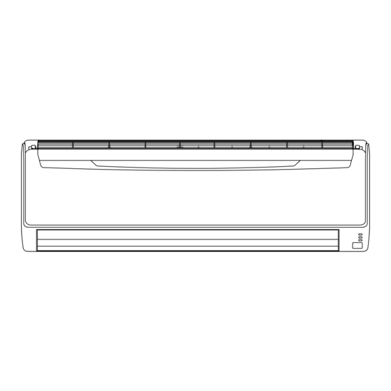
Page 5: Part 1. Indoor Unit
Part 1. INDOOR UNIT WALL MOUNTED TYPE: ASU18RLF ASU24RLF... -
Page 6: Specifications
1. Specifications Wall mounted Type Inverter heat pump Model name ASU18RLF ASU24RLF Power supply 208/230 V ~ 60 Hz Available voltage range 187—253 V 5.28 6.44 Rated Btu/h 18,000 22,000 Cooling 2.05—6.74 2.90—8.00 Min.—Max. Btu/h 7,000—23,000 9,900—27,300 Capacity 6.30 7.38... -
Page 7: Dimensions
2. Dimensions 2-1. Models: ASU18RLF and ASU24RLF Unit: in (mm) 39-5/16 (998) 20-1/2 (520) 23-1/4 (590) 9 (228) 1 (25) 28-3/8 (721) 1-7/16 (37) 13/16 (20) Unit center 15-3/4 (400) 17-5/16 (439) 11/16 x 7/16 (18 x 11) hole 5/8 (16) - Page 8 ¢ Installation space requirement Provide sufficient installation space for product safety. Unit: in (mm) Outline of unit 3 (52) or more 3 (53) or more 4 (80) or more 5 (120) or more 60 (1,500) or more - 4 -...
-
Page 9: Wiring Diagrams
3. Wiring diagrams 3-1. Models: ASU18RLF and ASU24RLF - 5 -... -
Page 10: Capacity Table
Airflow Rate (AFR): For cooling capacity: Total Capacity (TC), Sensible Heat Capacity (SHC), and Input Power (IP) For heating capacity: Total Capacity (TC) and Input Power (IP) 4-1. Cooling capacity ¢ Model: ASU18RLF Indoor temperature °FDB °FWB °FDB... - Page 11 ¢ Model: ASU24RLF Indoor temperature °FDB °FWB °FDB kBtu kBtu kBtu kBtu kBtu kBtu 19.12 11.45 0.30 21.30 11.51 0.30 23.48 12.56 0.31 24.19 13.56 0.31 25.64 13.52 0.32 27.11 14.39 0.32 19.10 11.47 0.37 21.28 11.54 0.38 23.46 12.58 0.38 24.17 13.59...
-
Page 12: Heating Capacity
4-2. Heating capacity ¢ Model: ASU18RLF Indoor temperature °FDB °FDB °FWB kBtu kBtu kBtu kBtu kBtu 18.80 1.76 18.37 1.80 17.91 1.83 17.46 1.87 17.02 1.90 20.67 2.28 20.20 2.33 19.70 2.37 19.19 2.42 18.72 2.46 22.67 2.65 22.13 2.70 21.60... -
Page 13: Fan Performance
5. Fan performance 5-1. Air velocity distributions ¢ Model: ASU18RLF Fan speed Operation mode Measuring conditions HIGH (ft) Unit: ft/s (m/s) Top view Vertical airflow direction louver: Up 7 (2) 3 (1) 2 (0.5) Horizontal airflow direction louver: Center (ft) - Page 14 (ft) Unit: ft/s (m/s) 7 (2) Side view 3 (1) Vertical airflow direction louver: Down 2 (0.5) Horizontal airflow direction louver: Center (ft) - 10 -...
- Page 15 ¢ Model: ASU24RLF Fan speed Operation mode Measuring conditions HIGH (ft) Unit: ft/s (m/s) Top view 7 (2) 3 (1) Vertical airflow direction louver: Up Horizontal airflow direction louver: Center 2 (0.5) (ft) (ft) Unit: ft/s (m/s) 3 (1) 2 (0.5) 7 (2) Top view Vertical airflow direction louver: Up...
-
Page 16: Airflow
5-2. Airflow ¢ Model: ASU18RLF Cooling Fan speed Airflow HIGH QUIET Heating Fan speed Airflow HIGH QUIET - 12 -... - Page 17 ¢ Model: ASU24RLF Cooling Fan speed Airflow 1,120 HIGH QUIET Heating Fan speed Airflow 1,150 HIGH QUIET - 13 -...
-
Page 18: Operation Noise (Sound Pressure)
6. Operation noise (sound pressure) 6-1. Noise level curve ¢ Model: ASU18RLF Cooling Heating NC-65 NC-65 NC-60 NC-60 NC-55 NC-55 NC-50 NC-50 HIGH HIGH NC-45 NC-45 NC-40 NC-40 NC-35 NC-35 NC-30 NC-30 NC-25 NC-25 QUIET QUIET NC-20 NC-20... -
Page 19: Sound Level Check Point
6-2. Sound level check point Microphone Microphone 3 ft 3 in (1 m) -3/8 NOTE: Detailed shape of the actual indoor unit might be slightly different from the one illustrated above. - 15 -... -
Page 20: Safety Devices
7. Safety devices Model Type of protection Protection form ASU18RLF ASU24RLF Circuit protection Current fuse (PCB*) 250 V, 3.15 A Terminal protection Current fuse 250 V, 3 A More than 185°F (85°C) Activate Fan motor speed down Thermistor protection Less than 185°F (85°C) -
Page 21: External Input And Output
8. External input and output With using external input and output functions, this product can be operated inter-connectedly with an external device. Connector Input Output Remarks CN14 Control input — See external input/output settings for details. CN16 — Operation status output 8-1. - Page 22 Circuit diagram example • Contact capacity: DC 24 V or more, 10 mA or Indoor unit more. Connected unit control PCB • *: Make the distance from the PCB to the con- Connector Example: Switch nected unit within 33 ft (10 m). •...
-
Page 23: External Output
8-2. External output With using external output function, operating status of this product can be transmitted to the ex- ternal device, and also, this product can be inter-connected with the external device. ¢ Operation status output Air conditioner operation status signal can be output. ... -
Page 24: Remote Controller
9. Remote controller 9-1. Wireless remote controller ¢ Overview a FAN button Selects the fan speed (AUTO, HIGH, MED, LOW, and QUIET). b START/STOP button Starts and stops operation. c SET button (vertical) Adjusts the vertical airflow direction. d SET button (horizontal) Adjusts the horizontal airflow direction. - Page 25 ¢ Specifications Controller Unit: in (mm) Top view 3/4 (19) 2-3/16 (56) Front view Side view Rear view Size (H × W × D) in (mm) 6-11/16 × 2-3/16 × 3/4 (170 × 56 × 19) Weight oz (g) 3 (85) (without batteries) NOTE: Actual number of buttons might be different from the figure above.
-
Page 26: Function Settings
10. Function settings To adjust the functions of this product according to the installation environment, various types of function settings are available. NOTE: Incorrect settings can cause a product malfunction. 10-1. Function settings by using remote controller Some function settings can be changed on the remote controller. After confirming the setting pro- cedure and the content of each function setting, select appropriate functions for your installation environment. - Page 27 STEP 2: Selecting the function number and setting value 1. Press the SET TEMP. ( ) buttons to select the function Function number number. To switch between the left and right digits, press the MODE button. 2. Press the FAN button to proceed the setting value. To return the function number selection, press the FAN button again.
- Page 28 ¢ Contents of function setting Each function setting listed in this section is adjustable in accordance with the installation environ- ment. NOTE: Setting will not be changed if invalid numbers or setting values are selected. Function setting list Function no. Functions Filter sign 30/31...
- Page 29 2) Room temperature control for indoor unit sensor NOTE: Before performing this setting, refer to Function 95. Depending on the installed environment, correction of the room temperature sensor may be re- quired. Select the appropriate control setting according to the installed environment. The temperature correction values show the difference from the Standard setting "00"...
- Page 30 5) Remote controller custom code (Only for wireless remote controller) The indoor unit custom code can be changed. Select the appropriate custom code. Function number Setting value Setting description Factory setting ♦ 6) External input control "Operation/Stop" mode or "Forced stop" mode can be selected. Function number Setting value Setting description...
- Page 31 8) Room temperature control for wired remote controller sensor NOTE: Before performing this setting, refer to Function 95. Depending on the installed environment, correction of the room temperature sensor may be re- quired. Select the appropriate control setting according to the installed environment. To change this setting, set Function 42 to "Both"...
- Page 32 ¢ Custom code setting for wireless remote controller To interconnect the air conditioner and the wireless remote controller, assignment of the custom code for the wireless remote controller is required. NOTE: Air conditioner cannot receive a custom code if the air conditioner has not been set for the custom code.
-
Page 33: Accessories
11. Accessories Part name Exterior Q’ty Part name Exterior Q’ty Operating manual Drain hose insulation Installation manual Cloth tape Tapping screw (large), Wall hook bracket M4 × 25 mm Tapping screw (small), Remote controller M3 × 12 mm Battery Air cleaning filter Remote controller Air cleaning filter frame holder... -
Page 34: Optional Parts
12. Optional parts 12-1. Controllers Exterior Part name Model name Summary Monitor Mo 10:00AM Large and full-dot liquid crystal Mode Set temp. Wired remote screen, wide and large keys easy to ° F Cool High UTY-RVNUM Icon check: controller press, user-intuitive arrow key. Menu Wire type: Polar 3-wire Room temperature can be controlled... -
Page 35: Part 2. Outdoor Unit
Part 2. OUTDOOR UNIT SINGLE TYPE: AOU18RLXFWH AOU24RLXFWH... -
Page 36: Specifications
1. Specifications Type Inverter heat pump Model name AOU18RLXFWH AOU24RLXFWH Power supply 208/230 V ~ 60 Hz Available voltage range 187—253 V Starting current 10.5 Cooling 1,489 (2,530) 2,001 (3,400) Airflow rate CFM (m Heating 1,489 (2,530) 2,119 (3,600) Type × Q'ty Propeller fan ×... -
Page 37: Dimensions
2. Dimensions 2-1. Models: AOU18RLXFWH and AOU24RLXFWH Unit: in (mm) Top view 1-1/4 3(77) 35-3/8 (900) (12) 13 (330) (31) 15-3/4 (400) Front view Side view 25-5/8 (650) Airflow 5-3/4 (147) 6-3/4 (170) Bottom view - 33 -... -
Page 38: Installation Space
3. Installation space 3-1. Models: AOU18RLXFWH and AOU24RLXFWH ¢ Space requirement Provide sufficient installation space for product safety. Single outdoor unit installation • When the upper space is open: Unit: in (mm) When there are obstacles at the rear only. When there are obstacles at the rear and sides. - Page 39 Multiple outdoor unit installation • When the upper space is open: Unit: in (mm) When there are obstacles at the rear only. When there are obstacles at the front only. 60 (1,500) or more 10 (250) 12 (300) or more or more When there are obstacles at the front and rear.
- Page 40 Outdoor unit installation in multi-row Unit: in (mm) Single parallel unit arrangement Multiple parallel unit arrangement 6 (150) or more 20 (500) or more 79 (2,000) or more 119 (3,000) or more 24 (600) or more 24 (600) or more 60 (1,500) or more 40 (1,000) or more 10 (250) or more...
-
Page 41: Refrigerant Circuit
4. Refrigerant circuit 4-1. Models: AOU18RLXFWH and AOU24RLXFWH Heat exchanger 3-way valve 3-way valve (INDOOR) (large) (small) Muffler Pressure switch 4-way valve Strainer Expansion valve Strainer Heat exchanger (OUTDOOR) Cooling Heating - 37 -... -
Page 42: Wiring Diagrams
5. Wiring diagrams 5-1. Model: AOU18RLXFWH - 38 -... -
Page 43: Model: Aou24Rlxfwh
5-2. Model: AOU24RLXFWH - 39 -... -
Page 44: Capacity Compensation Rate For Pipe Length And Height Difference
6. Capacity compensation rate for pipe length and height difference Height difference H Indoor unit is higher than outdoor unit Indoor unit is lower than outdoor unit Outdoor unit Indoor unit Outdoor unit Indoor unit Connection pipe Connection pipe 6-1. Models: AOU18RLXFWH and AOU24RLXFWH NOTE: Values mentioned in the table are calculated based on the maximum capacity. -
Page 45: Additional Charge Calculation
7. Additional charge calculation 7-1. Models: AOU18RLXFWH and AOU24RLXFWH Refrigerant type R410A lb oz 4 lb 10.1 oz Refrigerant amount 2,100 ¢ Refrigerant charge 66 or less 164 (Max.) Total pipe length 0.43 oz/ft 20 or less 50 (Max.) 14.1 28.2 42.3 (40 g/m) -
Page 46: Airflow
8. Airflow 8-1. Model: AOU18RLXFWH Cooling 2,530 1,489 Heating 2,530 1,489 8-2. Model: AOU24RLXFWH Cooling 3,400 2,001 Heating 3,600 1,000 2,119 - 42 -... -
Page 47: Operation Noise (Sound Pressure)
9. Operation noise (sound pressure) 9-1. Noise level curve ¢ Model: AOU18RLXFWH Cooling Heating NC-65 NC-65 NC-60 NC-60 NC-55 NC-55 NC-50 NC-50 NC-45 NC-45 NC-40 NC-40 NC-35 NC-35 NC-30 NC-30 NC-25 NC-25 NC-20 NC-20 NC-15 NC-15 1,000 2,000 4,000 8,000 1,000... -
Page 48: Sound Level Check Point
9-2. Sound level check point Rear Microphone Microphone Airflow 39-3/8 in (1 m) Side view Rear view NOTE: Detailed shape of the actual outdoor unit might be slightly different from the one illustrat- ed above. - 44 -... -
Page 49: Electrical Characteristics
10. Electrical characteristics Model name AOU18RLXFWH AOU24RLXFWH Voltage 208/230~ Power supply Frequency MCA *1 17.0 18.0 Starting current MAX. CKT. BKR *3 Power cable Wiring spec. Connection cable *4 Limited wiring length ft (m) 167 (51) *1: Minimum Circuit Ampacity (Calculation based on UL1995) *2: Selected sample based on Japan Electrotechnical Standards and Codes Committee E0005. -
Page 50: Safety Devices
11. Safety devices Model Type of Protection form protection AOU18RLXFWH AOU24RLXFWH Current fuse (Filter PCB) 250 V, 5 A × 2 250 V, 3.15 A Circuit protection Current fuse (Main PCB) 250 V, 5 A Current fuse (Out of PCB) 250 V, 5 A 302±27 °F (150±15 °C) Activate... -
Page 51: Accessories
12. Accessories Part name Exterior Q’ty Part name Exterior Q’ty Adapter, 12.7 (1/2)→15.88 (5/8) Installation manual [mm (in)] (Only for 18 model) Adapter, 6.35 (1/4)→9.52 (3/8) Drain pipe [mm (in)] Drain cap - 47 -...
Need help?
Do you have a question about the ASU18RLF and is the answer not in the manual?
Questions and answers