Advertisement
Quick Links
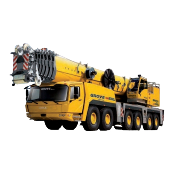
Grove GMK
North American Product Guide
L
Features
•
USt capacity
•
, m
full power MEGAFORM™ boom with
TWIN LOCK™ pinning
•
m
bi fold swingaway
•
x m
•
, t
hydraulic removal system
•
MEGATRAK™ independent hydro pneumatic
suspension
m
ft
ft seven section
m
ft
ft hydraulic o set
ft intermediate lattice inserts
,
lb counterweight with
Advertisement

Related Manuals for Manitowoc Grove GMK6300L


Summary of Contents for Manitowoc Grove GMK6300L
- Page 1 Grove GMK North American Product Guide Features • USt capacity • ft seven section full power MEGAFORM™ boom with TWIN LOCK™ pinning • ft hydraulic o set bi fold swingaway • ft intermediate lattice inserts • lb counterweight with hydraulic removal system •...
- Page 2 Features Introducing the Grove GMK MEGATRAK™ e MEGATRAK™ suspension system is the best o road driveline available on the market today. e system’s versatility and performance allows the GMK L to operate as a true all-terrain crane. e MEGATRAK™ independent suspension and all-wheel steer system allows wheels to remain on the ground at all times so stresses and weight are not continually transferred between axles.
- Page 3 Contents Specifications Dimensions Weights Counterweight Working range main boom Load charts main boom Working range O settable swingaway Load charts O settable swingaway Working range O settable swingaway with inserts Load charts O settable swingaway with inserts Working range Hydraulic lu ng jib Load charts Hydraulic lu ng jib Symbols glossary...
-
Page 4: Specifications
Specifications Superstructure Boom All aluminum constructed cab with acoustical lining, hydraulic tilted to 20°. Includes tinted safety glass, adjustable operator’s seat, opening windows at side 15,6 m - 80 m (51 ft - 263 ft) 7-section, full power and rear, hinged windshield with wiper, sun visor MEGAFORM™ boom with TWIN-LOCK™ Pinning. - Page 5 Specifications Carrier Superstructure continued Chassis Hoist Main and auxiliary hoist are powered by axial piston motor Box type, torsion resistant frame is fabricated from high with planetary gear and brake. “Thumb-thumper” hoist strength steel. drum rotation indicator alerts operator of hoist movement. Main Auxiliary Outrigger system...
- Page 6 Specifications Carrier continued Electrical system Suspension 24V system with three phase alternator, 28V/100A 2 batteries, 12V/170 Ah Grove exclusive MEGATRAK™ suspension. Independent hydro-pneumatic system acting on all wheels with hydraulic lockout. Suspension can be raised 170 mm Maximum speed (6.7 in) or lowered 126 mm (5.0 in), both longitudinally and transversely.
- Page 7 Dimensions Slewing pivot Tires ° ° ° ° ° ° ° ° ° Ra = Radius all wheels steered *Lowered Grove GMK6300L...
- Page 8 Weights Trailing boom - PROVISIONAL Basic Weights - kg (lb) Axles 1 and 2 Axles 4 - 6 Three dolly axle Total GMK6300L Mercedes power with 20.5R25 tires, 12x8x12 drive/steer, retarder, 12 m - 21 m (39 ft - 69 ft) hydraulic luffing 14 334 (31,601) 41 171...
- Page 9 Counterweight Center of gravity Counterweight Grove GMK...
-
Page 10: Working Range
Working range Main boom ft main boom ° Operating radius in feet from axis of rotation Hook heights shown in the working diagram do not consider loaded boom deflection. Hook block ton, sheave . ft ton, sheave . ft ton, sheave . -
Page 11: Load Charts
Load charts Main boom Counterweight Outriggers ft in spread ˚ . ft . ft Pounds x Boom Extension Feet * Over the rear with special equipment Loads greater than 376,000 lb can only be lifted with special equipment. THIS CHART IS ONLY A GUIDE AND SHOULD NOT BE USED TO OPERATE THE CRANE. Grove GMK The individual crane’s load chart, operating instructions and other instructional plates must be read and understood prior to operating the crane... - Page 12 Load charts Main boom Outriggers Counterweight ft in spread ˚ . ft . ft Pounds x Boom Extension Feet Loads greater than 376,000 lb can only be lifted with special equipment. THIS CHART IS ONLY A GUIDE AND SHOULD NOT BE USED TO OPERATE THE CRANE. The individual crane’s load chart, operating instructions and other instructional plates must be read and understood prior to operating the crane...
- Page 13 Load charts Main boom Counterweight Outriggers ft in spread ˚ . ft . ft Pounds x Boom Extension Feet Counterweight Outriggers ft in spread ˚ . ft . ft Pounds x Boom Extension Feet Loads greater than 376,000 lb can only be lifted with special equipment. THIS CHART IS ONLY A GUIDE AND SHOULD NOT BE USED TO OPERATE THE CRANE.
- Page 14 Load charts Main boom Counterweight Outriggers ft in spread ˚ . ft . ft Pounds x Boom Extension Feet Counterweight Outriggers ft in spread ˚ . ft . ft Pounds x Boom Extension Feet Loads greater than 376,000 lb can only be lifted with special equipment. THIS CHART IS ONLY A GUIDE AND SHOULD NOT BE USED TO OPERATE THE CRANE.
- Page 15 Load charts Main boom Counterweight Outriggers ft in spread ˚ . ft . ft Pounds x Boom Extension Feet Outriggers Counterweight ft in spread ˚ . ft . ft Pounds x Boom Extension Feet Counterweight Outriggers ft in spread ˚ .
- Page 16 Working range Hydraulic offsettable swingaway ft main boom with ft swingaway ° ° ° ° Operating radius in feet from axis of rotation Hook heights shown in the working diagram do not consider loaded boom deflection.
- Page 17 Load charts Hydraulic offsettable swingaway Intermediate angle and loads for luffing Counterweight Outriggers ft in spread ˚ Pounds x Boom Extension Feet . ' + . ' + . ' + . ' + ° ° ° ° ° ° °...
-
Page 18: Load Chart
Load chart Hydraulic offsettable swingaway Intermediate angle and loads for luffing Counterweight Outriggers ft in spread ˚ Pounds x Boom Extension Feet . ' + . ' + . ' + . ' + ° ° ° ° ° ° °... - Page 19 Working range Hydraulic offsettable swingaway with inserts ft main boom with ft swingaway and X ft inserts ° ° ° ° Operating radius in feet from axis of rotation Hook heights shown in the working diagram do not consider loaded boom deflection. Grove GMK...
- Page 20 Load chart Hydraulic offsettable swingaway with inserts Counterweight Outriggers ft in spread ˚ Pounds x Boom Extension Feet . ' + . ' + . ' + . ' + ° ° ° ° ° ° ° ° ° ° °...
- Page 21 Load chart Hydraulic offsettable swingaway with inserts Counterweight Outriggers ft in spread ˚ Pounds x Boom Extension Feet . ' + . ' + . ' + . ' + ° ° ° ° ° ° ° ° ° ° °...
- Page 22 Working range Integrated heavy duty jib Heavy duty jib . ft + . ' ° Operating radius in feet from axis of rotation Hook heights shown in the working diagram do not consider loaded boom deflection.
- Page 23 Working range Integrated heavy duty jib Fixed angle Counterweight Outriggers . ft x . ft spread ˚ . ft Pounds thousands Boom Extension Feet . ' + . ' . ' + . ' . ' + . ' . + . ' .
- Page 24 Load chart Integrated heavy duty jib Fixed angle Outriggers Counterweight ˚ . ft x . ft spread . ft Pounds thousands Boom Extension Feet . ' + . ' . ' + . ' . ' + . ' . + . ' .
-
Page 25: Symbols Glossary
Symbols glossary Axles Counterweight Grade Gear Boom Drive Radius Heavy duty jib Hoist Boom elevation Electrical system Rotation Boom extension Engine Hookblock Speed Extension Hydraulic system Steering Boom length Boom nose Frame Lights Suspension Brakes Fuel tank capacity Swing Outrigger controls Outriggers Tires Transmission... - Page 26 Regional headquarters Manitowoc - Americas Manitowoc - Europe, Middle East, Africa Manitowoc - Asia Pacific Manitowoc, Wisconsin, USA Ecully, France Shanghai, China Tel: + Tel: + Tel: + Fax: + Fax: + Fax: + Shady Grove, Pennsylvania, USA Tel: +...
Need help?
Do you have a question about the Grove GMK6300L and is the answer not in the manual?
Questions and answers