Advertisement
®
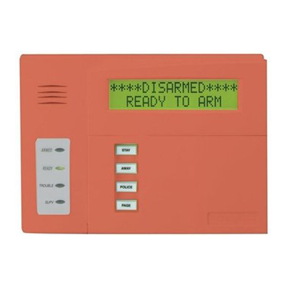
Keypad Features
• Programmable function keys
• Built-in sounder
• Ready, Armed, Supervisory and Trouble LEDs
• RED keypad for Commercial Fire applications
Notes:
1.
Function key applications are control-dependent and may differ from one control to another (see control's instructions for details).
2.
Trouble and Supervisory LED operation is an option on some controls (see control's instructions for details).
Keypad address may be set to address 00 through 30 to operate with these controls (see control's instructions for details).
3.
GENERAL INFORMATION
The 6160CR is an addressable remote keypad that is
intended for use in commercial applications with
ADEMCO Group control panels, as listed above. The
6160CR's address is set locally, via the keypad's keys,
depending on the control being used (see note 3,
above). The keys are continuously backlit for
convenience. The LCD display is backlit only when a
key is depressed, or when the system is in alarm or
trouble condition.
Note:
On
some
controls,
programmed to remain on at all times (see control's
instructions for details).
KEYPAD LED INDICATIONS
The keypad's LEDs will light under the following
conditions:
Lights when the system is "READY"
READY
to arm; all zones are intact
Lights when the system is armed in
ARMED
any mode (AWAY, STAY, etc.)
Lights when a supervisory condition
SUPERVISORY*
exists (see control's instructions for
details)
Lights when a trouble condition exists
TROUBLE*
(see control's instructions for details)
* The LEDs will temporarily extinguish while the display shows other
status conditions. For example, if a trouble condition is displayed, the LED
is ON. When the display indicates a different condition (FAULT of a
burglary zone for instance), the LED will extinguish, but will turn back ON
when the display again indicates the trouble condition.
SPECIAL FUNCTION KEYS
The keypad also features programmable function
keys labeled A, B, C, and D. These keys may be
programmed to initiate panic, fire, or emergency
alarms as well as other special functions such as
macros, paging, and single-button operation. (Not all
controls support these special functions. Refer to the
individual control panel's instructions for details.)
These keys must be held down for at least 2 seconds
to initiate the assigned function.
INSTALLATION GUIDE
(* see note 1)
(* see note 2)
the
LCD
may
Commercial Alpha Keypad
Supported Control Panels
VISTA-32FB
(* see note 3)
VISTA-128FB
(* see note 3)
WIRING AND INSTALLATION
The keypad may be surface-mounted directly to a dry
wall or to a single- or double-gang electrical box.
1. Remove the case back by inserting a thin-
bladed screwdriver, in turn, against each of the
two snap-open tabs (see Figure 1 below). Pry apart
the case back as each tab is depressed.
2. Route wiring going to the keypad through the
large rectangular opening in the case back.
3. Mount the case back to the wall or electrical
box.
be
4. Wire directly from the keypad's terminal block
(see Figure 2) to the terminal block on the control
panel (see control's Summary of Connections label
for correct terminal connections).
Wiring Table (All Keypads)
Keypad
Control Panel
DO
Data Out
+
+ Aux. Pwr
–
– Aux Pwr (GND)
DI
Data In
5. Reattach the keypad to its case back.
Hint: Insert top end first and then snap shut the
lower end.
K3590-ADCFV1 8/01
6160CR
Wire Color
Yellow
Red
Black
Green
Figure 1
6160CR-005-V0
Advertisement
Table of Contents

Related Manuals for ADEMCO 6160CR


Summary of Contents for ADEMCO 6160CR
- Page 1 Keypad address may be set to address 00 through 30 to operate with these controls (see control's instructions for details). GENERAL INFORMATION WIRING AND INSTALLATION The 6160CR is an addressable remote keypad that is The keypad may be surface-mounted directly to a dry intended for use in commercial applications with wall or to a single- or double-gang electrical box.
- Page 2 (e.g., fire, police, emergency, etc.) is provided. These labels come in four colors (red, blue, green, and white) and may be placed on the appropriate function keys (A, B, C, or D) for ease 6160CR-004-V0 identifying individual key’s...
Need help?
Do you have a question about the 6160CR and is the answer not in the manual?
Questions and answers