Advertisement
Table of Contents
Advertisement
Table of Contents

Related Manuals for Visionis VIS-8011


Summary of Contents for Visionis VIS-8011
- Page 1 Access Control RF Wireless 2.4GHz Indoor Receiver VIS-8011 / VIS-8012 User Manual...
-
Page 2: Specifications
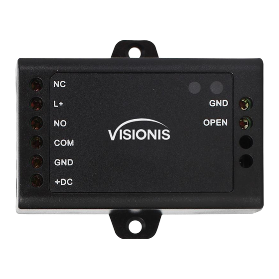
Specifications Operating Voltage 12V DC ±20% Mini Controller Current ≤20uA Idle Current ≤40mA Working Current Communication Frequency 2.4G Communication Distance 15m Maximum (50 feet) Relay Contact Load 2Amp Maximum Environment Indoor Operating Temperature -20°C~60°C (-4°F~140°F) Operating Humidity 0%~86%RH Physical ABS Shell Dimensions 65L ×... - Page 3 Connection Diagram Common Power Supply: PROGRAMMING Enter and Exit Program Mode Programming Step Keystroke Combination * (Master Code) # 1. Enter Program Mode (Factory default is 123456) 2. Exit Set Master Code Programming Step Keystroke Combination 1. Enter Program Mode * (Master Code) # 0(New Master Code)#(Repeat New 2.
- Page 4 Programming Step Keystroke Combination 1. Enter Program Mode * (Master Code) # 1 (User ID) # (PIN) # (Repeat PIN) # 2. Add PIN The PINs can be added continuously 3. Exit Add User Card(s) User ID: 0~499 Card type: 125 KHz EM card Programming Step Keystroke Combination 1.
-
Page 5: Set Buzzer
Set Access Mode Programming Step Keystroke Combination 1. Enter Program Mode * (Master Code) # 2. PIN Access 3 0 # PIN + Card Access 3 1 # PIN or Card Access 3 2 # (factory default) 3. Exit Set Relay Configuration The relay configuration sets the behavior of the output relay on activation. -
Page 6: Reset To Factory Default
OTHERS Users Operation Programming Step Keystroke Combination PIN User Access (PIN) # Card User Access # (Read Card) PIN + Card User Access # (Read Card) (PIN) # Pair Wireless Keypad / Exit Button and Mini Controller 1) They all are already paired when out of factory, if no problem, the users do not need to do this operation in using. 2) One Mini Controller can be connected by five pcs of Wireless Keypad and Exit Button maximum. - Page 7 VIS-8011 / VIS-8012 - Simplified Instruction Function description Operation * (123456) # Enter the Program Mode then you can do the programming (123456 is the factory default master code) 0 (New Code) # (Repeat the New Code) # Change the Master Code...
Need help?
Do you have a question about the VIS-8011 and is the answer not in the manual?
Questions and answers