Brother P-Touch QL-570 Service Manual
Hide thumbs
Also See for P-Touch QL-570:
- User manual (106 pages) ,
- Set up and operation manual (100 pages) ,
- Setup & operation manual (45 pages)
Table of Contents
Advertisement
Advertisement
Table of Contents
Troubleshooting

Related Manuals for Brother P-Touch QL-570


Summary of Contents for Brother P-Touch QL-570
- Page 1 P-touch SERVICE MANUAL MODEL: QL-570...
- Page 2 PREFACE This publication is a service manual covering the specifications, theory of operation, disassembly/reassembly procedure, and troubleshooting the Brother QL-570. It is intended for service personnel and other concerned persons to accurately and quickly provide after-sale service for our QL-570.
-
Page 3: Table Of Contents
CONTENTS CHAPTER I SPECIFICATIONS ................I-1 MECHANICAL SPECIFICATIONS ................I-1 1.1.1 External Appearance ..................I-1 1.1.2 Keyboard......................I-1 1.1.3 Display ....................... I-2 1.1.4 Printing Mechanism ................... I-2 1.1.5 Thermal Tape..................... I-3 1.1.6 Cutter ......................... I-4 1.1.7 PC Interface ....................... I-4 ELECTRONICS SPECIFICATIONS ................. - Page 4 MAIN PCB ......................... II-8 2.3.1 Logic Components ..................... II-9 [ 1 ] CPU ........................ II-9 [ 2 ] EEPROM ......................II-9 2.3.2 Key, LED Circuit....................II-9 2.3.3 Head and Motor Power Supply ON/OFF Circuit..........II-10 2.3.4 Full Cutter Motor Driver Circuit and Media Feed Motor Driver Circuit....II-11 2.3.5 Media Type Detect Sensor Circuit, Media Position Detect Sensor Circuit and Cover Open Sensor Circuit ................
- Page 5 [ 3 ] Installing the Mecha ASSY ................III-35 [ 4 ] Installing the Upper Cover ................III-36 [ 5 ] Installing the Panel Cover................III-39 [ 6 ] Installing the Side Cover L, R ................. III-42 [ 7 ] Installing the Media PCB ASSY..............
-
Page 6: Chapter I Specifications
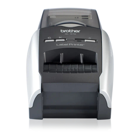
CHAPTER I SPECIFICATIONS MECHANICAL SPECIFICATIONS 1.1.1 External Appearance [ 1 ] Dimensions (W x D x H) 134mm x 208mm x 141mm (Excluding the bottom legs) [ 2 ] Weight Approx. 1.12kg (Machine proper only) Approx. 2.12kg (In package) 141mm 134mm 208mm Fig. -
Page 7: Display
1.1.3 Display [ 1 ] Display type LED 1 (ON/OFF: Green light ON/OFF, Error: Red light blinking, Cover Opened: Orange light ON, Cooling: Orange light blinking) 1.1.4 Printing Mechanism [ 1 ] Print method Direct thermal printing with thermal head Printing on thermal paper tape, and printing on thermal paper and thermal plastic tape (with fixed head and tape feeding) -
Page 8: Thermal Tape
1.1.5 Thermal Tape [ 1 ] Tape Roll type (Die cut and free length) [ 2 ] Type and size of die cut tape Roll overall Number of label Label size Type of tape width sheets (W x H) Standard Address 29mm x 90mm 32mm 400 sheets/roll... -
Page 9: Cutter
Microsoft Windows 2000 Professional Microsoft Windows XP Professional Microsoft Windows XP Home Edition Microsoft Windows Vista [ 3 ] Printer emulation PT CBP (Brother original) [ 4 ] Accessories Editor Dedicated editor is included. USB IF cable Standard USB cable is included. -
Page 10: Chapter Ii Theory Of Operation
CHAPTER II THEORY OF OPERATION OUTLINE OF MECHANISMS 2.1.1 Print Mechanism ■ Structure of Thermal Head This machine adopts direct thermal printing system. The thermal head consists of 720 pieces of heating elements arrayed in vertical single row as shown in the Fig.2.1-1. The dimension of each heating element is vertical length 0.0847 (0.0847mm pitch) x horizontal width 0.13mm. -
Page 11: Press Contact And Release Mechanism Of Thermal Head
2.1.2 Press Contact and Release Mechanism of Thermal Head The head ASSY is pressed firmly against on the platen ASSY by the force of head spring L. When open the top cover, the release gear and release shaft are turned via link lever and platen release lever and the release shaft presses down the head ASSY. -
Page 12: Tape Feed Mechanism
2.1.3 Tape Feed Mechanism When the tape is fed, the tape is pressed against the thermal head, which is nipped between the platen and the thermal head. Here, the tape feed motor ASSY (step motor) rotates, of which drive power is transmitted via the gear train to the platen gear and the platen, and consequently the platen can feed the tape. -
Page 13: Automatic Tape Full Cutter Mechanism
2.1.4 Automatic Tape Full Cutter Mechanism The automatic tape full cutter mechanism moves the moving cutter blade up and down to the direction of the fixed cutter blade to cut the tape on the feeding pass. The cam is rotated once so that the moving cutter blade moves up and down and cuts a medium. -
Page 14: Cover Open (Cover Lock) Sensor
2.1.5 Cover Open (Cover Lock) Sensor The cover open (cover lock) sensor (push switch) is mounted on the SB PCB ASSY. Closing the top cover, the cover sensor arm pushes the cover open (cover lock) sensor (push switch) and the signal of top cover close status is output. -
Page 15: Outline Of Control Electronics
OUTLINE OF CONTROL ELECTRONICS Fig. 2.2-1 shows the block diagram of the control electronics. The control electronics consist of the following components. Fig. 2.2-1 Block Diagram of the Control Electronics 2.2.1 Main PCB ASSY This manages all the components. This PCB consists of CPU, EEPROM, USB chip and motor drivers etc. -
Page 16: Key, Led Pcb (Sb Pcb Assy
2.2.4 Key, LED PCB (SB PCB ASSY) This is the PCB equipped with ON/OFF button, Feed button, Cut button, cover open sensor and LED lamp (Green/Red). 2.2.5 Cutter Sensor (Cutter Home Position Detect Sensor) This sensor detects existence of the cutter at its home position (micro switch). 2.2.6 Media Feed Motor (Tape Feed Motor ASSY) The media feed motor supplies the drive power to feed media. -
Page 17: Main Pcb
MAIN PCB Fig. 2.3-1 shows the block diagram of the main PCB. The main PCB consists of the following components. (1) CPU (Including ROM and RAM) (2) EEPROM (4Kbit) (3) Power supply ON/OFF circuit, Feed button ON/OFF circuit, Cut button ON/OFF circuit, LED ON/OFF circuit (4) Head power supply ON/OFF circuit (5) Full cutter motor driver circuit and Media feed motor driver circuit... -
Page 18: Logic Components
2.3.1 Logic Components [ 1 ] CPU (U7) controls and manages the entire system, which is 32 bit microcomputer of NEC brand. This CPU contains the 256 Kbyte ROM that stores the control program data. The embedded 24 Kbyte RAM is used mainly for temporary storage of incoming data from PC. [ 2 ] EEPROM One 4Kbit EEPROM (U2) is used. -
Page 19: Head And Motor Power Supply On/Off Circuit
2.3.3 Head and Motor Power Supply ON/OFF Circuit Turning the CPU status of PDL10 (VHON, 81 pin) to High, top cover is closed, and turns cover open sensor Low, Q10 turns on, V (25V power supply) turns on and consequently the head and motor is energized. -
Page 20: Full Cutter Motor Driver Circuit And Media Feed Motor Driver Circuit
2.3.4 Full Cutter Motor Driver Circuit and Media Feed Motor Driver Circuit Full Cutter motor driver circuit This circuit drives the DC motor to cut a medium as described in subsection “2.1.4 Automatic Tape Full Cutter Mechanism”. When the CPU receives cut request from the “Cut button ON/OFF circuit (refer to 2.3.2(3))”, it confirms that the top cover ASSY is closed, and turns VHON (81 pin) high. -
Page 21: Media Type Detect Sensor Circuit, Media Position Detect Sensor Circuit And Cover Open Sensor Circuit
2.3.5 Media Type Detect Sensor Circuit, Media Position Detect Sensor Circuit and Cover Open Sensor Circuit Media type detect sensor circuit The sensor circuit consists of media sensor with five switch systems (CAS1 through CAS5). Loading a tape cassette, some of five switches turn on and the others retain off according to the configuration of its' ID code apertures. - Page 22 Media type No media (not loaded) Standard Address Large Address Small Address Sipping Multi purpose File Folder CD/DVD Square Paper Round Paper 12 Round Paper 24 Continuous Length Paper 12 Continuous Length Paper 29 Continuous Length Paper 62 Continuous Length Paper 62 White Removable Continuous Length Paper 62 Yellow Removable Continuous Length Film White 29 Continuous Length Film White 62...
- Page 23 Media position detect sensor circuit When performing printing and FEED motion through the process described in subsection “2.3.4 (2) Media feed motor driver circuit”, the CPU reads the sensor value to detect the medium position. The CPU receives the voltage of the media position detect sensor (reflective photo sensor) sent through CN4 and input it through SENTAN (100 pin).
-
Page 24: Head Temperature Detect Circuit
2.3.6 Head Temperature Detect Circuit This circuit measures the temperature described below. Head temperature: The CPU determines the ambient temperature of the head from the AD converted voltage value input to TH (98 pin) of the CPU via CN3. Thermal head Fig. -
Page 25: Reset Circuit
2.3.8 Reset Circuit When power is supplied from the power supply PCB, +3.3V is supplied, and power is supplied to the CPU. At this point, if +3.3V voltage line goes over +2.8V, the reset circuit (U5) sets High to the RESET input (14 pins) of the CPU, clearing the RESET status of the CPU. -
Page 26: Chapter Iii Disassembly And Reassembly
CHAPTER III DISASSEMBLY AND REASSEMBLY SAFETY PRECAUTIONS The disassembly or reassembly work should be carried on a grounded antistatic sheet. Otherwise, the LSIs and electronic parts may be damaged due to the electricity charged in your body. When transporting PCBs, be sure to wrap them in conductive sheets such as aluminum foil. -
Page 27: Tightning Torque Lists
TIGHTNING TORQUE LISTS Tightening torque Location Screw type Q’ty N•cm Lower plate ASSY Taptite, bind B M2.6x6 0.343 ± 0.049 Power supply ASSY Taptite, bind B M2.6x6 0.343 ± 0.049 Ground spring plate Taptite, bind B M2.6x6 0.343 ± 0.049 FG harness ASSY Taptite, bind B M2.6x6 0.343 ±... -
Page 28: Lubrication Points List
LUBRICATION POINTS LIST * Grease to be used: Grease B (rice-grain sized) Release shaft * Grease to be used: Grease B (rice-grain sized) * Grease to be used: Grease B (rice-grain sized) Head ASSY Mecha ASSY III- 3... - Page 29 Platen gear * Grease to be used: Silicon grease G501 (rice-grain sized) Double gear C III- 4...
-
Page 30: Disassembly Procedure
DISASSEMBLY PROCEDURE [ 1 ] Removing the Top Cover and Thermal Tape Note: Turn on the power supply with top cover closed, initialize the machine before disassembly. (1) Turn off the power supply and remove the AC cord. AC cord Power button Fig.3.1-1 Removing the Top Cover and Thermal Tape (1) (2) Open the top cover. - Page 31 (4) Remove the link lever from the top cover. Top cover Link lever Fig.3.1-3 Removing the Top Cover and Thermal Tape (3) (5) Push the ribs of the upper cover inward, and remove the top cover. Bosses Top cover Top cover Ribs Upper cover Upper cover...
-
Page 32: 2 ] Removing The Front Cover And Tray S
[ 2 ] Removing the Front Cover and Tray S (1) Open the front cover. (2) Push the ribs of the front cover inward, and remove it from the main body. Main body Front cover Fig.3.1-5 Removing the Front Cover and Tray S (1) (3) Bend the tray S and remove it from the front cover. -
Page 33: 3 ] Removing The Power Supply Assy And Main Pcb Assy
[ 3 ] Removing the Power Supply ASSY and Main PCB ASSY (1) Turn the main body upside down. (2) Remove the four screws, and then remove the lower plate ASSY. Screws Screws Lower plate ASSY Main body Fig.3.1-7 Removing the Power Supply ASSY and Main PCB ASSY (1) (3) Remove the two screws, and then remove the power supply ASSY. - Page 34 (4) Remove the main PCB harness from the power supply ASSY. (5) Remove the power8 harness ASSY from the main PCB ASSY. Power supply ASSY Power8 harness ASSY Main PCB harness Main PCB ASSY Fig.3.1-9 Removing the Power Supply ASSY and Main PCB ASSY (3) (6) Remove the power8 harness ASSY from the power supply ASSY.
- Page 35 (7) Remove the filament tape which secures the harness of CN11. Filament tape Main PCB ASSY CN11 Fig.3.1-11 Removing the Power Supply ASSY and Main PCB ASSY (5) (8) Remove the five connectors (CN5, CN7, CN8, CN10, CN11) and two flat cables (CN3, CN4) from the main PCB ASSY.
- Page 36 (9) Remove the three screws, and then remove the ground spring plate, FG harness ASSY and main PCB ASSY. Screw Ground spring plate FG harness ASSY Screws Main PCB ASSY Fig.3.1-13 Removing the Power Supply ASSY and Main PCB ASSY (7) (10) Remove the insulating sheet S from the under cover.
-
Page 37: 4 ] Removing The Sub Assy Inlet
[ 4 ] Removing the Sub ASSY Inlet (1) Remove the solder of the sub ASSY inlet from the power supply ASSY. Sub ASSY inlet harness Power supply ASSY Sub ASSY inlet harness Power supply ASSY Fig.3.1-15 Removing the Removing the Sub ASSY Inlet (1) (2) Release the hooks on both sides of the sub ASSY inlet and pull the inlet to the direction of the arrow as shown in the figure below to remove it. -
Page 38: 5 ] Removing The Media Pcb Assy
[ 5 ] Removing the Media PCB ASSY (1) Remove the two screws, and then remove the media PCB ASSY from the under cover. Screws Media PCB ASSY Under cover Fig.3.1-17 Removing the Media PCB ASSY III- 13... -
Page 39: 6 ] Removing The Side Cover L, R
[ 6 ] Removing the Side Cover L, R (1) Turn the main body upside down, and remove the two screws from the under cover. Screw Under cover Screw <Bottom of main body> Fig.3.1-18 Removing the Side Cover L, R (1) (2) Detach the Portion A of the side cover L by hooking your nail on it, and then slightly lift the rear side of the side cover L from the main body. - Page 40 (3) Remove the three hooks on the lower side of the side cover L, and then remove the side cover L in the arrow direction. Side cover L Hook Hooks Fig.3.1-20 Removing the Side Cover L, R (3) (4) Remove the two screws from the under cover. Screw Under cover Screw...
- Page 41 (5) Detach the Portion A of the side cover R by hooking your nail on it, and then slightly lift the rear side of the side cover R from the main body. “A” Side cover R Fig.3.1-22 Removing the Side Cover L, R (5) (6) Remove the three hooks on the lower side of the side cover R, and then remove the side cover R in the arrow direction.
-
Page 42: 7 ] Removing The Panel Cover
[ 7 ] Removing the Panel Cover (1) Remove the two screws, and then remove the panel cover from the upper cover. Panel cover Screws <A view> Under cover A view Upper cover Panel cover Fig.3.1-24 Removing the Panel Cover (1) (2) Turn the panel cover upside down. - Page 43 (4) Remove the power button, feed button and LED guide from the panel cover. LED guide Power button Feed button Panel cover Fig.3.1-26 Removing the Panel Cover (3) (5) Remove the cover sensor arm from the panel cover. Cover sensor arm Panel cover Fig.3.1-27 Removing the Panel Cover (4) III- 18...
-
Page 44: 8 ] Removing The Upper Cover
[ 8 ] Removing the Upper Cover (1) Remove the two screws A and three screws B from the upper cover. (2) Release the three hooks to remove the upper cover from the under cover. Note: The screws A are screw, bind B M2.6x4. The screws B are taptite, bind B M2.6x6. Screws B Screws A Hooks... - Page 45 (4) Remove the two screws, and then remove the insert guide from the upper cover. Screw Screw Insert guide Upper cover Fig.3.1-30 Removing the Upper Cover (3) (5) Remove the tape sensor PCB ASSY from the insert guide. Insert guide Tape sensor PCB ASSY Fig.3.1-31 Removing the Upper Cover (4) III- 20...
-
Page 46: 9 ] Removing The Mecha Assy
[ 9 ] Removing the Mecha ASSY (1) Remove the two screws, and then remove the mecha ASSY from the under cover. Screws Mecha ASSY Hook Hook Under cover Hook Fig.3.1-32 Removing the Mecha ASSY III- 21... -
Page 47: 10 ] Removing The Cutter Unit Assy
[ 10 ] Removing the Cutter Unit ASSY (1) Remove the two screws, and then remove the cutter unit ASSY from the mecha ASSY. Mecha ASSY Cutter unit ASSY Screws Fig.3.1-33 Removing the Cutter Unit ASSY (1) (2) Remove the cutter caution label from the cutter unit ASSY. Cutter unit ASSY Cutter caution label Fig.3.1-34 Removing the Cutter Unit ASSY (2) -
Page 48: 11 ] Disassembly Of The Mecha Assy
[ 11 ] Disassembly of the Mecha ASSY (1) Release the hook and remove the double gear C from the mecha ASSY. Hook Double gear C Mecha ASSY Fig.3.1-35 Disassembly of the Mecha ASSY (1) (2) Remove the double gear B and platen gear in the sequence from mecha ASSY. Mecha ASSY Double gear B Platen gear... - Page 49 (3) Remove a screw from the platen shaft bush on the right side to remove the platen shaft bush (right side). Platen ASSY Screw Platen shaft bush (Right side) Mecha ASSY Fig.3.1-37 Disassembly of the Mecha ASSY (3) (4) Remove the platen shaft bush (left side) and platen ASSY from the mecha ASSY. Platen shaft bush (Left side) Platen ASSY...
- Page 50 (5) Remove the head hold spring from the mecha ASSY. Head ASSY Head hold spring Mecha ASSY Fig.3.1-39 Disassembly of the Mecha ASSY (5) (6) Remove the head ASSY from the mecha ASSY. Caution: Pay attention not to give strong impact on the heating element of a head ASSY when removing the head ASSY.
- Page 51 (7) Remove the one lower foot from the bottom of the flat cable of the head ASSY. Lower foot Head ASSY Flat cable Fig.3.1-41 Disassembly of the Mecha ASSY (7) (8) Remove the two head springs L from the mecha ASSY. Head springs L Mecha ASSY Fig.3.1-42 Disassembly of the Mecha ASSY (8)
- Page 52 (9) Remove the retaining ring E2.5 and remove the double gear A from the mecha ASSY. Mecha ASSY Double gear A Retaining ring E2.5 Fig.3.1-43 Disassembly of the Mecha ASSY (9) (10) Remove two screws, and then remove the tape feed motor ASSY and FG harness ASSY.
-
Page 53: Reassembling Procedure
REASSEMBLING PROCEDURE [ 1 ] Reassembling the Mecha ASSY (1) Assemble the tape feed motor ASSY and FG harness ASSY onto the mecha ASSY with the two screws. Note: Pay attention to the direction of the tape feed motor ASSY. Mecha ASSY Tape feed motor ASSY Screws... - Page 54 (3) Turn over the flat cable of the head ASSY, and assemble the lower foot. Lower foot Head ASSY <A view> Head ASSY Flat cable Lower foot * Assemble the lower foot in a way that it comes to the position shown in the figure above when Flat cable the flat cable is restored to the original A view...
- Page 55 (5) Set the two head springs L on the bosses of the head ASSY, and assemble the head ASSY onto the mecha ASSY as shown in the figure. Note1: Confirm that the head ASSY moves smoothly Note2: Confirm that the head springs L are properly inserted into the upper and lower bosses.
- Page 56 Assemble the head hold spring onto the mecha ASSY as shown in the figure. Note: Be careful not to cut your fingers. Head hold spring Mecha ASSY Fig.3.2-6 Reassembling of the Mecha ASSY (6) III- 31...
- Page 57 (7) Assemble the platen shaft bush (left side) to the mecha ASSY. (8) Assemble the platen ASSY to the mecha ASSY. Platen shaft bush (Left side) Platen ASSY Mecha ASSY Fig.3.2-7 Reassembling of the Mecha ASSY (7) (9) Assemble the platen shaft bush (right side) to the mecha ASSY by screw. Platen ASSY Screw Platen shaft bush...
- Page 58 (10) Assemble the platen gear, double gear B, and double gear C onto the mecha ASSY in this order. Note1: Confirm that the hook of the double gear C is securely hooked on. Note2: Confirm that each gear moves smoothly. Mecha ASSY Double gear B Platen gear...
-
Page 59: 2 ] Installing The Cutter Unit Assy
[ 2 ] Installing the Cutter Unit ASSY (1) Attach the cutter caution label onto the cutter unit ASSY. Cutter unit ASSY Cutter caution label Fig.3.2-10 Installing the Cutter Unit ASSY (1) (2) Assemble the cutter unit ASSY onto the mecha ASSY with the two screws. Mecha ASSY Cutter unit ASSY Screws... -
Page 60: Installing The Mecha Assy
[ 3 ] Installing the Mecha ASSY (1) Set the two hooks A to the grooves on the under cover of the mecha ASSY. (2) Fit the hole of the mecha ASSY into the boss on the under cover, and insert the two hooks B of the mecha ASSY into the holes on the under cover. -
Page 61: 4 ] Installing The Upper Cover
[ 4 ] Installing the Upper Cover (1) Insert the tape sensor PCB ASSY into the insert guide. Note1: Insert the tape sensor PCB ASSY until it hits the groove of the insert guide. Note2: Confirm that you can see the tape sensor PCB ASSY from the hold of the insert guide. - Page 62 (4) Bend the flat cable as shown in the figure, and secure it with filament tape on the back side of the upper cover. Filament tape Flat cable Upper cover Fig.3.2-16 Installing the Upper Cover (3) (5) Move the platen release lever and link lever to the position as shown in the figure. (The head is in a pressure contact state.) Mecha ASSY Platen release lever...
- Page 63 (6) Put the flat cable of the tape sensor PCB ASSY through the portion A of the under cover. (7) Put the SB PCB harness through the portion B of the under cover. Under cover “A” “B” SB PCB harness Flat cable of the Tape sensor PCB ASSY Fig.3.2-18 Installing the Upper Cover (5)
-
Page 64: 5 ] Installing The Panel Cover
[ 5 ] Installing the Panel Cover (1) Assemble the power button, feed button and LED guide onto the panel cover. LED guide Power button Feed button Panel cover Fig.3.2-20 Installing the Panel Cover (1) (2) Assemble the shaft unit of the cover sensor arm to the portion A of the panel cover. Cover sensor arm Panel cover “A”... - Page 65 (3) Assemble the SB PCB ASSY onto the panel cover with the three screws. Note: Confirm that the Cover sensor arm moves smoothly. Screws SB PCB ASSY Panel cover Fig.3.2-22 Installing the Panel Cover (3) (4) Insert the two hooks of the panel cover into the holes of the upper cover. Holes Hook Upper cover...
- Page 66 (5) Rotate the panel cover using the hooks as fulcrums, and assemble it onto the upper cover. (6) Secure the panel cover with the two screws. Note: Confirm that the harnesses are not pinched. Hooks Panel cover Screws <A view> A view Panel cover Upper cover...
-
Page 67: 6 ] Installing The Side Cover L, R
[ 6 ] Installing the Side Cover L, R (1) Catch the three hooks A of the side cover L with the under cover. (2) Catch the four hooks B of the side cover L with the upper cover, and assemble it. Hook B Side cover L Hook A... - Page 68 (4) Catch the three hooks C of the side cover R with the under cover. (5) Catch the four hooks D of the side cover R with the upper cover, and assemble it. Side cover R Hook D Hook C Hooks D Hooks C Fig.3.2-28 Installing the Side Cover L, R (3)
-
Page 69: 7 ] Installing The Media Pcb Assy
[ 7 ] Installing the Media PCB ASSY (1) Assemble the media PCB ASSY with the two screws. Important: When replacing the media PCB ASSY, and then check the items using the “MAINTENANCE SOFTWARE OPERATION” in APPENDIX 1. Screws Media PCB ASSY Main body Fig.3.2-30 Installing the Media PCB ASSY [ 8 ]... - Page 70 (3) Solder the harnesses of the sub ASSY inlet to the power supply ASSY as shown in the figure. Sub ASSY inlet harness Power supply ASSY Fig.3.2-32 Installing the Sub ASSY Inlet (2) (4) Route the harness of the sub ASSY inlet as shown in the figure. Front Hook Under cover...
-
Page 71: 9 ] Installing The Power Supply Assy And Main Pcb Assy
[ 9 ] Installing the Power supply ASSY and Main PCB ASSY (1) Attach the insulating sheet S onto the under cover as shown in the figure below. Insulating sheet S Under cover Fig.3.2-34 Installing the Power supply ASSY and Main PCB ASSY (1) (2) Assemble the ground spring plate, FG harness ASSY and main PCB ASSY with the three screws. - Page 72 (3) Connect the power8 harness ASSY into the power supply ASSY. Power8 harness ASSY Power supply ASSY Fig.3.2-36 Installing the Power supply ASSY and Main PCB ASSY (3) (4) Connect the power8 harness ASSY into the main PCB ASSY. (5) Connect the main PCB harness into the power supply ASSY. Power supply ASSY Power8 harness ASSY Power8 harness ASSY...
- Page 73 (6) Assemble the power supply ASSY onto the under cover with the two screws. Note: Confirm that the sub ASSY inlet harness is not pinched. Screws Under cover Power supply ASSY Sub ASSY inlet harness Fig.3.2-38 Installing the Power supply ASSY and Main PCB ASSY (5) (7) Connect the five connectors (CN5, CN7, CN8, CN10, CN11) and two flat cables (CN3, CN4) into the main PCB ASSY.
- Page 74 (8) Route the harnesses of CN8, CN10, CN11 and FG harness as shown in the figure. (9) Secure the harness of CN11 with the filament tape. Slit Filament tape Slit CN11 Slit Slit Main PCB ASSY CN11 CN10 FG harness FG harness Fig.3.2-40 Installing the Power supply ASSY and Main PCB ASSY (7) (10) Assemble the lower plate ASSY onto the main body with the four screws.
-
Page 75: 10 ] Installing The Front Cover And Tray S
[ 10 ] Installing the Front Cover and Tray S (1) Assemble the tray S onto the front cover. Tray S Front cover Fig.3.2-42 Installing the Front Cover and Tray S (1) (2) Assemble front cover onto the main body. (3) Close the front cover. -
Page 76: 11 ] Installing The Top Cover And Thermal Tape
[ 11 ] Installing the Top Cover and Thermal Tape (1) Insert one of the two bosses of the top cover into the corresponding rib hole of the upper cover, and then insert the other boss to the rib hole by bending the rib. Bosses Top cover Top cover... - Page 77 (3) Assemble the thermal tape onto the main body. (4) Close the top cover. Thermal tape Top cover Fig.3.2-46 Installing the Top Cover and Thermal Tape (3) III- 52...
-
Page 78: 12 ] Demonstration Print And Final Check
[ 12 ] Demonstration Print and Final Check (1) Insert the AC cord into a outlet. (2) Set the tape with the maximum width (62mm), and press the Feed button six times in a row while pressing the ON/OFF button when the power is OFF. Then, leave your fingers from the both buttons, and 100mm full-width gray print is performed. -
Page 79: Chapter Iv Troubleshooting And Error Message
CHAPTER IV TROUBLESHOOTING AND ERROR MESSAGE This section gives the service personnel some of the troubleshooting procedures to be followed if an error or malfunction occurs with this machine. It is impossible anticipate all of the possible troubles which may occur in future and determine the troubleshooting procedures, so this chapter covers some sample troubles. -
Page 80: Led Control In Different Situations And Measure Against Errors
LED CONTROL IN DIFFERENT SITUATIONS AND MEASURE AGAINST ERRORS The display priority is specified as follows. - Green LED ON: Normal operation - Orange LED ON: Cover open - Orange LED blinking by 1.6 sec frequency: In a cooling state - Red LED blinking by 0.8 sec frequency: Error. -
Page 81: Error Message
ERROR MESSAGE A list of the error messages that are indicated on the printer monitor is shown below: Error Messages Advices No Errors. None. A roll of labels or tape is Install into the P-touch the roll of labels or tape indicated on the not installed. - Page 82 Error Messages Advices Not enough memory to Wait until any other application(s) is finished and then try to print document. print again. Not enough disk space to Ensure sufficient disk space. spool document. The cooling operation is The cooling operation is underway. Wait for a while. underway.
- Page 83 A list of the error messages that are indicated while the service person tool is being used is shown below. Check Item Error Error Messages Advices Write default Communication Cannot transmit. Check the power supply and the EEPROM data(0) error USB connector.
-
Page 84: Troubleshooting Flows
TROUBLESHOOTING FLOWS [ 1 ] Printing is performed with specific dots omitted. IV- 6... -
Page 85: 2 ] The Tape Is Not Detected Correctly
[ 2 ] The tape is not detected correctly. IV- 7... -
Page 86: 3 ] Led Does Not Turn On
[ 3 ] LED does not turn on. IV- 8... -
Page 87: 4 ] No Printing Is Performed
[ 4 ] No printing is performed. [ 5 ] The interface malfunction. IV- 9... -
Page 88: 6 ] The Tape Is Not Cut
[ 6 ] The tape is not cut. IV- 10... -
Page 89: 7 ] The Tape Is Not Fed Correctly
[ 7 ] The tape is not fed correctly. IV- 11... -
Page 90: Appendix 1 Maintenance Software Operation
APPENDIX 1. MAINTENANCE SOFTWARE OPERATION This software has the feature to adjust and examine every component mounted on a mechanical component or the main PCB ASSY when it is replaced, and the capability to write the information such as the model name and serial number into the EEPROM mounted on the main PCB ASSY. - Page 91 1.4 Auto power-off setting tool This tool is used to set the correct auto power-off time for models to particular destinations and with particular main PCB. Auto power-off setting Sets auto power-off time.
-
Page 92: Appendix 1.1 Purpose And Use Procedure Of The Reset Software Tool (Ql500Tstreset.exe)
APPENDIX 1.1 Purpose and Use Procedure of the Reset Software Tool (ql500tstReset.exe) Note: Be sure to reset the EEPROM before making an examination after repair work is done. This tool serves to reset the EEPROM. <Operating Procedure> (1) Start the reset software. (File name: ql500tstReset.exe) The following screen appears. - Page 93 (3) Press the [Check SerNo.] button, and “NG” is displayed as the check result, and the present serial No. is displayed in the “Results” column. Fig. 2 (4) Press the [Reset EEPROM] button to reset the EEPROM of the main unit to the initial state (factory default).
- Page 94 (5) Turn OFF the power of the main unit, and then turn it ON again. (6) Press the [Check SerNo.] button. If “OK” is displayed as the check result, and if the serial No. displayed in the “Results” column is “B00000001”, the reset operation is complete. Fig.
-
Page 95: Appendix 1.2 Setting And Use Procedures Of The Maintenance Software Tool (Ql570Tstse.exe)
APPENDIX 1.2 Setting and Use Procedures of the Maintenance Software Tool (ql570tstSE.exe) [ 1 ] Setting Procedure of Maintenance Software (1) Start the maintenance software. (File name: ql570tstSE.exe) Fig. 5 (2) Connect the machine to your PC with the USB cable and turn the ON/OFF button ON. Note: When new hardware is detected and the “New hardware detection wizard”... - Page 96 (3) Read the serial number in the rating plate on the under cover using the barcode reader. The serial number is loaded to the “Serial No.:” column. If you do not have the barcode reader, manually input the lower 9 digits of the serial number in the rating plate on the under cover from the keyboard.
- Page 97 (5) “General Settings” Set various items before the inspection. (5-1) (5-2) Fig. 7 (5-1) “Print pattern” Specify a file for each print pattern. - Setting of print pattern files In accordance with the table below, specify a file for each print pattern of the “Print pattern”...
- Page 98 [ 2 ] Use Procedure of Maintenance Software (1) Start up this software. (2) Connect the machine to your PC with the USB cable and turn the ON/OFF button ON. (3) Enter the serial number from the keyboard. [ 2-1 ] “Write default EEPROM data” Reset the setting value of the EEPROM to the factory default value.
- Page 99 [ 2-2 ] “Tape sensor check” (1) Click the [(1) Tape sensor check] button. The following screen appears. (Fig. 10) Fig. 9 Fig. 10...
- Page 100 (2) Set only the backing paper (release paper) of the die-cut tape (62mm x 100mm) on the main unit. (Be sure to remove the label.) Align the printed mark (sensor black mark) on the backing paper to the position indicated in the figure. Tape sensor PCB ASSY Backing paper (release paper)
- Page 101 (4) Remove the paper from the main unit, and then click the [Sensor black level check (2)] button. If the standards are satisfied, “OK” is displayed in the “Black level:” column. (5) If all the check results are OK, click the [OK] button to go on to the next test. Important: If NG appears in the “Adjust value”...
- Page 102 [ 2-3 ] “Media & cover sensors check” Check that the cover open sensor and media sensor work correctly. (1) Click the [(2) Media&cover sensors check] button. Fig. 14...
- Page 103 (2) Press the cover sensor arm. (3) Check that the last word of the message in the “Results” column is switched into “on” or “off”. (4) Press the media sensor. (5) Check that the last word of the message in the “Results” column is switched into “on” or “off”.
- Page 104 (7) If the check result is OK, click the [(2) Quit sensors check] button. If NG, click the [Sensors test NG] button. Fig. 17...
- Page 105 [ 2-4 ] “Cut test” Check that the tape is fed and cut correctly. (1) Click the [(3) Cut test] button. Fig. 18 (2) Set the free length roll of 62mm into the machine. (3) Press the Feed button on the machine. If OK, the “feed test OK”...
- Page 106 (4) Press the Cut button on the machine. If OK, the “feed and cut test OK” message appears in the “Results” column. Cut button Fig. 20 (5) Click the [(3) Quit cut test] button to finish the cut test mode.
- Page 107 [ 2-5 ] “Temperature check” Check that the head temperature sensor works properly. (1) Click the [(4) Temperature check] button. If the standards are satisfied, “OK” is displayed in the “Results” column. Fig. 21...
- Page 108 [ 2-6 ] “Adjustment print test” Implement the printing test to adjust the energy rank and top and bottom margins. (1) Click the [(5) Adjustment print test] button. The following screen appears. (Fig. 23) Fig. 22 Fig. 23 Note: The [OK] button is disabled before these two types of adjustment are completed.
- Page 109 (2) Set the free length roll of 62mm into the machine and click the [Print test(continuous) (2)] button to implement the test print. Fig. 24 (3) Press the Cut button on the machine. (4) Measure the top margin of the print result. It is OK if the top margin is 3mm±0.5mm. 3mm±0.5mm Printing direction Fig.
- Page 110 (5) If the top margin is out of the range of 3mm±0.5mm, change the value in the “Adjusted value” column so that the top margin is 3mm±0.5mm. Then, click the [Apply (0)] button. When adjustment is complete, “OK” is displayed in the “Apply result:” column. Fig.
- Page 111 (7) If the check result is OK, Set the die cut roll of 62mm x 100mm into the machine and click the [Print test(DieCut) (1)] button to implement the test print. Fig. 28 (8) Measure the top margin of the print result. It is OK if the top margin is 3mm±0.5mm. 3mm±0.5mm Printing direction Fig.
- Page 112 (9) If the top margin is out of the range of 3mm±0.5mm, change the value in the “Adjusted value” column so that the top margin is 3mm±0.5mm. Then, click the [Apply (0)] button. Fig. 30 (10) Click the [Print test(DieCut) (1)] button again to implement the test print. Then, check that the top margin of the print result is 3mm±0.25mm.
- Page 113 [ 2-7 ] “Write serial number” Write the USB serial number into the EEPROM. - Click the [(8) Write serial number] button. - When the USB serial number is written normally, “OK” appears on the left hand side of the button, and the message appears in the “Results” column. Fig.
-
Page 114: Appendix 1.3 Use Procedure Of The Vr Adjustment Tool (Ql500Tstvradjust.exe)
APPENDIX 1.3 Use Procedure of the VR Adjustment Tool (ql500tstVRAdjust.exe) Be sure to make this adjustment in any of the following cases: - When you replace the main PCB ASSY - When you replace the tape sensor PCB ASSY - When you replace the media PCB ASSY - When the tape sensor check in the maintenance software tool (ql570tstSE.exe) failed <Operating Procedure>... - Page 115 (3) Set only the backing paper (release paper) of the die-cut tape (62mm x 100mm) on the main unit. Tape sensor PCB ASSY Backing paper (release paper) Upper cover Fig. 34 (4) Click the [VR adjustment] button. Fig. 35...
- Page 116 (5) If the value indicated in the “Results” column of the VR adjustment tool is in the range of 218 to 222, the result is OK. If it is out of the range and NG, proceed to the next adjustment. <In the case of OK: The numeric value displayed is within the range of 218 to 222.>...
- Page 117 (6) When NG is displayed in the “Results” column, adjust the VR value. Remove the volume cover label from the upper cover ASSY. (7) Turn the VR adjustment volume provided in the machine with using a screwdriver so that the value indicated in the “Results” column is in the range of 218 to 222. (Make sure that a screwdriver is put into the slit on the volume and turn it slowly.
- Page 118 (8) After adjustment, attach a brand-new volume cover label onto the adjustment hole on the upper cover. Brand-new volume cover label Upper cover Adjustment hole Fig. 39 (9) Click the [Quit VR adjustment] button. Fig. 40...
- Page 119 (10) Click the [Exit] button to finish the software. (11) Turn off the ON/OFF button of the machine. This is the end of the adjustment. Note: Be sure not to activate the maintenance software and P-Touch editor at the same time. They do not work properly if they are activated at a time.
-
Page 120: Appendix 1.4 Auto Power-Off Setting Tool (Autopoff.exe)
APPENDIX 1.4 Auto Power-OFF Setting Tool (autopoff.exe) Be sure to use this tool to change the auto power-off setting for all models satisfy conditions below. 1. Russian model. 2. Mounted main PCB ASSY is "LBC080001 (parts code)". Note: This tool must be used after running the maintenance software tool (ql570tstSE.exe). Performing in wrong order would cause invalid auto power-off setting in the product. - Page 121 (4) Once the auto power-off setting is written properly, the window below appears. Press the [OK] button to close auto power-off setting tool. Fig. 43 Window appears when the writing completed properly Note: When the auto power-off setting is failed on writing, the window below appears. (1) When the connected printer is not same with printer selected on auto power-off setting tool, error message below appears.
- Page 122 Sep., 2007 SM-PT002 (3)
Need help?
Do you have a question about the P-Touch QL-570 and is the answer not in the manual?
Questions and answers