Table of Contents
Advertisement
Quick Links
DVD AV RECEIVER
AVH-P5900DVD
DVD RDS AV RECEIVER
AVH-P5900DVD
AVH-P5900DVD
This service manual should be used together with the following manual(s):
Model No.
Order No.
CX-3212
CRT3896
"DTS" and "DTS Digital Surround" are registered trademarks of Digital Theater Systems,Inc.
Dolby noise reduction manufactured under license from Dolby Laboratories Licensing Corporation.
"Dolby" and the double-D symbol are trademarks of Dolby Laboratories Licensing Corporation.
For details, refer to "Important Check Points for Good Servicing".
PIONEER CORPORATION
PIONEER ELECTRONICS (USA) INC. P.O. Box 1760, Long Beach, CA 90801-1760, U.S.A.
PIONEER EUROPE NV Haven 1087, Keetberglaan 1, 9120 Melsele, Belgium
PIONEER ELECTRONICS ASIACENTRE PTE. LTD. 253 Alexandra Road, #04-01, Singapore 159936
PIONEER CORPORATION 2007
Mech.Module
MS5
DVD Mech. Module : Circuit Descriptions, Mech. Descriptions, Disassembly
4-1, Meguro 1-chome, Meguro-ku, Tokyo 153-8654, Japan
AVH-P5900DVD/XN/UC
Remarks
ORDER NO.
CRT3915
/XN/UC
/XNEW5
/XN/RE
K-ZZU. MAY 2007 Printed in Japan
Advertisement
Table of Contents

Related Manuals for Pioneer AVH-P5900DVD/XN/UC


Summary of Contents for Pioneer AVH-P5900DVD/XN/UC
- Page 1 PIONEER CORPORATION 4-1, Meguro 1-chome, Meguro-ku, Tokyo 153-8654, Japan PIONEER ELECTRONICS (USA) INC. P.O. Box 1760, Long Beach, CA 90801-1760, U.S.A. PIONEER EUROPE NV Haven 1087, Keetberglaan 1, 9120 Melsele, Belgium PIONEER ELECTRONICS ASIACENTRE PTE. LTD. 253 Alexandra Road, #04-01, Singapore 159936 PIONEER CORPORATION 2007 K-ZZU.
-
Page 2: Safety Information
1. During repair or tests, minimum distance of 13 cm from the focus lens must be kept. 2. During repair or tests, do not view laser beam for 10 seconds or longer . 2. The triangular label is attached to the mechanism unit frame. On the top of the player. AVH-P5900DVD/XN/UC... - Page 3 CAUTION Danger of explosion if battery is incorrectly replaced. Replaced only with the same or equivalent type recommended by the manufacture. Discord used batteries according to the manufacture's instructions. AVH-P5900DVD/XN/UC...
- Page 4 To protect products from damages or failures during transit, the shipping mode should be set or the shipping screws should be installed before shipment. Please be sure to follow this method especially if it is specified in this manual. AVH-P5900DVD/XN/UC...
-
Page 5: Table Of Contents
11.3 MONITOR PCB.............................164 11.4 DVD CORE UNIT..........................168 11.5 COMPOUND UNIT(A) AND COMPOUND UNIT(B) ................172 11.6 RCA PCB ..............................173 11.7 UPPER PCB ............................174 11.8 OPT PCB ..............................175 11.9 MAIN PCB UNITSERVICE), SWITCH PCB UNIT AND VOLUME PCB UNIT........176 12. ELECTRICAL PARTS LIST.........................177 AVH-P5900DVD/XN/UC... -
Page 6: Service Precautions
Red-circled area: The heat from hot parts on the B-side of the board is removed from the product bottom through a heat transfer sheet. Be careful not to burn yourself with the hot area. Bottom is a trademark of DVD Format/Logo Licensing Corporation. AVH-P5900DVD/XN/UC... - Page 7 Compared with eutectic solders, lead-free solders have higher bond strengths but slower wetting times and higher melting temperatures (hard to melt/easy to harden). The following lead-free solders are available as service parts: Parts numbers of lead-free solder: GYP1006 1.0 in dia. GYP1007 0.6 in dia. GYP1008 0.3 in dia. AVH-P5900DVD/XN/UC...
-
Page 8: Specifications
2. SPECIFICATIONS 2.1 SPECIFICATIONS - AVH-P5900DVD/XN/UC AVH-P5900DVD/XN/UC... - Page 9 - AVH-P5900DVD/XNEW5 AVH-P5900DVD/XN/UC...
- Page 10 - AVH-P5900DVD/XN/RE AVH-P5900DVD/XN/UC...
-
Page 11: Disc/Content Format
2.2 DISC/CONTENT FORMAT AVH-P5900DVD/XN/UC... -
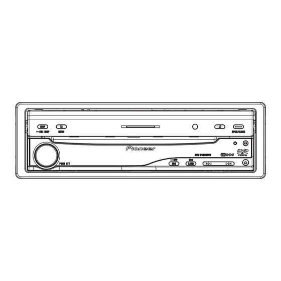
Page 12: Panel Facilities
2.3 PANEL FACILITIES AVH-P5900DVD/XN/UC... - Page 13 JGZ20P070FTC AVH-P5900DVD/XN/UC...
-
Page 14: Connection Diagram
2.4 CONNECTION DIAGRAM - Connection Diagram AVH-P5900DVD/XN/UC... -
Page 15: Basic Items For Service
See the table below for the items to be checked regarding video and audio: Item to be checked regarding video Item to be checked regarding audio Disturbed image (video jumpiness) Volume too high Too brig Mottled color AVH-P5900DVD/XN/UC... -
Page 16: Pcb Locations
Unit Number CZW5029 Upper PCB Unit Name Switch PCB Unit Unit Number YWX5005 Unit Number CZW5028 Unit Name DVD Core Unit Unit Name Volume PCB Unit Unit Number CWX3154 Unit Name Compound Unit(A) Unit Number CWX3394 Unit Name Compound Unit(B) AVH-P5900DVD/XN/UC... -
Page 17: Jig Connection Diagram
DVD Amp Assy <--> Monitor Unit 40-Pin + 20-Pin Relay PCB GGF1461 DVD Amp Assy <--> Main PCB Unit 20-Pin FFC GGD1209 DVD Amp Assy <--> Main PCB Unit Disc GGV1018 Skew adjustment TORX driver(T2) GGK1095 Skew adjustment Bond GEM1033 Skew adjustment AVH-P5900DVD/XN/UC... - Page 18 Before shipping out the product, be sure to clean the following portions by using the prescribed cleaning tools: Portions to be cleaned Cleaning tools DVD pickup lenses Cleaning liquid : GEM1004 Cleaning paper : GED-008 Portions to be cleaned Cleaning tools Fans Cleaning paper : GED-008 AVH-P5900DVD/XN/UC...
- Page 19 AVH-P5900DVD/XN/UC...
-
Page 20: Block Diagram
4. BLOCK DIAGRAM UPPER PCB MONITOR PART MONITOR PCB μ OSD & CON PART J K L DRIVE UNIT MOTHER UNIT SYSTEM PART POWER SUPPLY PART RCA PCB OPT PCB KEYBOARD UNIT AVH-P5900DVD/XN/UC... - Page 21 D E F DVD MECHANISM MODULE ARD UNIT AVH-P5900DVD/XN/UC...
- Page 22 Q231 MINI JACK/ REARV VIDEO9 MINIV AV-BUS& MINI VIDEO SW Q251 MINIJACK VIDEO ISO IC221 VIDEO5 IC141 NJM2233BM Q141 VCRSEL NJM2136V REARV Q841 Q842 VDD33V B.UP IC841 S-812C33AUA-C2N TUN3.3V Q851 VDD5 IC811 TUN+B TUN33V NJM2391DL1-33 IC851 S-812C50AUA-C3E iPod/AV-BUS IN AVH-P5900DVD/XN/UC...
- Page 23 CN1901 CN4201 CN1852 :AVH-P5900DVD/XNEW5 :AVH-P5900DVD/XN/RE :AVH-P5900DVD/XN/UC E.VOL CAPTAIN7 IC281 PML017A MUTE CN311 IPBUS+L Q311 IN4+ TUNER AUDIO ISO MS5L OUTFL IN2L IC401 TUN L Q313 IN3L CN4302 NJM2794RB2 OUTRL Q312 IN1L OUTPREL EVSEL RCAMUTE EVSCK EVSDA B.UP DATA Q741 SYSTEM MICON...
- Page 24 BA00DD0WHFP VIDEO5V Q801 VIDEO5 SENS33V Q911 VDD33 SENS33V SENS5 SENS5V Q921 VDD5 SENS5V SENS5 SWVDD5 Q853 VDD5 SWVDD5 SWVDD SWVDD33 IC852 VDD5 SWVDD33 BA00CC0WFP SWVDD :AVH-P5900DVD/XNEW5 SWVDD FIREWIRE PW :AVH-P5900DVD/XN/RE Q871 B.UP FWPW :AVH-P5900DVD/XN/UC Q875 PPOWER to 1/2 VDSENS AVH-P5900DVD/XN/UC...
- Page 25 BAND S4032 ATT&VOLUME RDTA RDTB CN481 S4031 RESET RESET DSENS SUB LCD CONTROL D4042 IC4001 LC75836WS Q4041 ILMA LCDCL SUBILM ILMB P1/S1 LCDCE SUB LCD LCDDI LCD4001 REMOTE CONTROL SENSOR IC4021 SBX3050-01 SWVDD5 D4051-D4060 ILMA ILMA D4071-D4080 ILMB ILMB AVH-P5900DVD/XN/UC...
- Page 26 3.3V REGULATOR PVCC5 Q5102 RESET 1,2,5,6 OVT1 IC5602 RESET SWVDD33V S-80827CNNB-B8M Q5101 OUT3 DDCON_SEL DDCON_SEL OUT4 OUT5 MVIPW CHARG REGU PNLYV PNLYV PNLXV PNLXY TOUCHAD TOUCHAD PNLVD PNLVD uPNLADX PNLADX uPNLADY PNLADY KDT1 KDT2 XOUT KST1 X5601 KST2 LSEN LSEN AVH-P5900DVD/XN/UC...
- Page 27 CN5002 CN5901 S5921 S5922 KDT1 KDT1 KDT2 DISP KDT2 KST1 KST1 S5923 S5924 KST2 KST2 TI/PGM/XM_MEMO OPEN/CLOSE D5901 Q5901 LSEN LSEN SWD33 ILMA ILMA ILMB ILMB DILMA TI/PGM/ DILMA DISC XM_MEMO DILMB ON/OFF DILMB DISP SWVDD33V SWD33 SWVDD33V OPEN/CLOSE AVH-P5900DVD/XN/UC...
- Page 28 VSENS VSENCE VIN3RF CN1951 VIN3 PR_A20 VIN4RF EXTRG1_SPD_SW EXTRG1 VIN4 SCLOCK SCLOCK VIN5 SDATA SDATA VIN6 EXTRG0 EXTRG0 CDMPD TRCCLK DVDMPD TRCCLK TRCD0 TRCDATA0 RFINN TRCD1 F+H_G+H TRCDATA1 TRCD2 TRCDATA2 E+G_E+F TRCD3 TRCDATA3 LPCO2 TRCST TRCST LPCO1 VCC33 VDD5 AVH-P5900DVD/XN/UC...
- Page 29 HOME SWITCH ACO1- ACO1+ CN1101 ACO2+ ACO2- TEMP 3.3V REG. IC1007 NJM2885DL1-33 VDD5 VCC33 CDMPD 78MD 1.2V REG. DVDMPD 65MD PU (DP8) IC1008 R1232D121B F+H_G+H F+H/G+H E+G_E+F E+G/E+F VCC12 Q1102 Q1104 LPCO2 LD(CD) Q1101 Q1103 LPCO1 LD(DVD) VREF VCC5 AVH-P5900DVD/XN/UC...
- Page 30 (ANG)MTR1 SWITCH (POS)MTR2 CN103 MTRS Q101 OUT2 ANGLE MOTER ANGLEOSW CN512 ANG_V 3.3V VR101 ANGLEIN ANG_IN ANGLE SENSER ANG_G WAVE SHAPE SLIDE PULSE OUTPUT VOLUME PCB UNIT IC104 IC105 TC7W14FU GP2L24B LIFTPUL LIFTSW DGND LIFT SW (EJECT:L) IC103 GP2L24B AVH-P5900DVD/XN/UC...
- Page 31 AVH-P5900DVD/XN/UC...
- Page 32 - CAW1946 AVH-P5900DVD/XN/UC...
-
Page 33: Diagnosis
Pin 140 2.45 [v] to 3.3 [v] = OFF ASENBO←H Standby Pin 30 SWVDD←H Pin 37 Starts communication with Display microcomputer. Source keys operative Source ON SYSPW←H Pin 6 Completes power-on operation. (After that, proceed to each source operation) AVH-P5900DVD/XN/UC... - Page 34 15. RLGND 5. BUS- 6. RR- 14. MUTE 16. RL 6. BUSG 7. FR+ 15. B. UP 17. SWRGND 7. BUSLI 8. RR+ 16. GND 18. SWR 8. ASENB 19. SMLGND 9. BUSRI 20. SWL 10. BUSRG 11. BUSLG AVH-P5900DVD/XN/UC...
- Page 35 OK? Execute check 10. Go to FE section check. Repair the defective part. Go to FE section check. Normal? FE section check. Go to FE related Is FE section repair process. normal? Replace the unit. Normal? AVH-P5900DVD/XN/UC...
- Page 36 <Check> Check the voltage at the “STANBY” test point while the power is on. Use the “DGND1” test point at the reference. Specification value Check point Module No. Unit VCC33 V- STANBY-DGND1 0.6 V or more Side A DGND1 STANBY Fig 1.1: STANBY check point AVH-P5900DVD/XN/UC...
- Page 37 Specification value Check point Module No. Unit VDD5_3 - DGND1 5.0 ± 0.4 VCC33_3 - DGND1 3.3 ± 0.15 VCC12_1 - DGND1 1.2 ± 0.12 Side A VDD5_3 VCC33 DGND1 VCC12_1 Fig 2.2: VDD5, VCC33, VCC12 voltage check points AVH-P5900DVD/XN/UC...
- Page 38 <Check> Check the voltage at the “XRES” test point while the power is on. Use the “DGND1” test point at the reference. Check point Module No. Specification value Unit VCC33 × 1 XRES-DGND1 0.7 or more Side A DGND1 XRES Fig 3.1: RESET check point AVH-P5900DVD/XN/UC...
- Page 39 <Check> Check the voltage at the “VSENS” test point while the power is on. Use the “DGND1” test point at the reference. Specification value Check point Module No. Unit VSENS - DGND1 VCC33 × 0.7 or more Side A DGND1 VSENS Fig 4.2: VSENS check point AVH-P5900DVD/XN/UC...
- Page 40 Specification value Check point Module No. Unit 27 MHz 2 IC1501 169pin ± 50 ppm Specification value Fig 5.2: Clock specification value Side A DGND1 IC1501 169pin Fig 5.3: 27 MHz check point AVH-P5900DVD/XN/UC...
- Page 41 Be careful as XCSM, XWE, XCAS, XRAS and XSCM of IC1481 are called differently in IC1501, namely NCSM, NWE, NCAS, NRAS, NCSM. IC1501 MA0~11 1481 DVD-LSI MDQ0~31 SDRAM XWE (NWE) XCAS (NCAS) XRAS (NRAS) XCSM (NCSM) DQM0 DQM1 DQM2 DQM3 Fig 6.1: SDRAM I/F AVH-P5900DVD/XN/UC...
- Page 42 256pin ± 5 % DQM1 Ω DQM2 IC1481 28pin IC1501 26pin ± 5 % Ω IC1481 59pin IC1501 27pin ± 5 % DQM3 Ω IC1501 8pin IC1481 22pin ± 5 % Ω IC1481 23pin IC1501 10pin ± 5 % AVH-P5900DVD/XN/UC...
- Page 43 Side B Check point 1 (IC1481) Side A Fig 6.2: SDRAM I/F check point Check point 2 (IC1501) AVH-P5900DVD/XN/UC...
- Page 44 Use the “PGND3 and AGND1” test point at the reference. Check point Module No. Specification value Unit VD8_1 - PGND3 8.0 ± 0.4 VD - PGND3 8.0 ± 0.4 VCC5_1- AGND1 5.0 ± 0.1 Side A VD8_1 AGND1 PGND3 VCC5_1 Fig 7.2: VD8, VCC5 voltage check points AVH-P5900DVD/XN/UC...
- Page 45 Check with PGND and GNDAU being the reference. Check point Module No. Specification value Unit VD - PGND_3 8.0 ± 0.4 AVCC5 - GNDAU1 5.0 ± 0.1 Side A PGND3 GNDAU AVCC5 Fig 8.2: VD8, AVCC5 voltage check points AVH-P5900DVD/XN/UC...
- Page 46 2.0 V~VCC33 V DGND~0.8 V 33.8688 MHz±300 ppm Specification value 1 Specification Specification value 2 value 3 Fig 9.2: Clock specification value Side A Check point 2 (IC1501 172 pin) Check point 1 (stylus) Fig 9.3: 27 MHz, DACCLK check point AVH-P5900DVD/XN/UC...
- Page 47 Waveform 2 LRCK VCC33 V-0.6 V or higher 0.4 V or lower Waveform 3 Specification value 2 Specification value 1 Fig 10.2: Serial 3 lines specification value Side A SRCK LRCK ADOUT3 Fig 10.3: Serial 3 lines check points AVH-P5900DVD/XN/UC...
- Page 48 1 400 ± 150 mV Waveform 4 1 400 ± 150 mV Waveform 4 Specification value is the root-mean-square value (rms). Fig 10.4: Analog audio out (LO, RO) specification value. Side A GNDAU1 Fig 10.5: Analog audio out check point AVH-P5900DVD/XN/UC...
- Page 49 Check 2pin cord after connecting it to a jig, etc. Specification value 2 Check point 1 (stylus) Specification value 1 Reference waveform 6 IEC VCC33 V-0.6 V or higher 0.4 V or lower Waveform 5 Side A Fig 10.6: Digital audio signal (IECOUT) check point AVH-P5900DVD/XN/UC...
- Page 50 ADOUT2 CLDCK AD3/DATA ADOUT3 DATA IEC/IPFLG IPFLG SBCK SBCK BMUTE BMUTE MCKENA High RIPP High EMPH EMPH EMPH Pins 1, 6, 8, 10, 12, 14, 16, 18, 20, 22 and 24 are GNDD. Fig 10.7: 6ch digital out/Ripping circuit AVH-P5900DVD/XN/UC...
- Page 51 VCC33 V-0.6 V or higher 0.4 V or lower SBCK VCC33 V-0.6 V or higher 0.4 V or lower VCC33 V x 0.3 V or lower RIPP Specification value 1 Specification value 2 Fig 10.8: 6ch digital out/Ripping specification value AVH-P5900DVD/XN/UC...
- Page 52 Side A SRCK LRCK ADOUT3 Side B ADOUT2 ADOUT1 ADOUT0 RIPP MCKENA SBCK Fig 10.9: 6ch digital out/Ripping check point AVH-P5900DVD/XN/UC...
- Page 53 Turn the volume (VR1671) to adjust the video level within the range of 1.0 ± 0.02 Vpp. The adjustment specification is 1.0 ± 0.02 Vpp. CN1901 AVCC5 HOST I/F IC1501 Q1701(NoMount) Video buffer circuit Video Q1702(NoMount) Video buffer circuit section Q1704(NoMount) Video buffer circuit Fig 11.3: Video circuit (component) AVH-P5900DVD/XN/UC...
- Page 54 Specification value BOTTOM PEAK Cb signal Specification value BOTTOM PEAK Cr signal Specification value BOTTOM 100% Color Bars signal Fig 11.4 Waveform for the case of component 100% Color Bars output Side A COMPO Fig 11.5: VIDEO signal check point AVH-P5900DVD/XN/UC...
- Page 55 (Refer to the FE test mode for the method of displaying the LD energizing time.) 2.If the second digit from the left of the energizing time display is showing E, such as “ E ”, it means that the flash memory has reached its life. Example: 0E000BB8 AVH-P5900DVD/XN/UC...
- Page 56 Reference voltage: DGND2 1 V/div. 500 nsec/div Waveform 7 G-> G-> Waveform 2 Waveform 5 [WHITE 100IRE] CH1 : LRCK CH1 : COMPO Reference voltage: DGND2 1 V/div. 5 μsec/div Reference voltage: GNDV1 200 mV/div. 10 μsec/div G-> Waveform 6 Waveform 3 AVH-P5900DVD/XN/UC...
-
Page 57: Service Mode
In order to F close after focus search (S character measurement mode), set to Power_OFF first then power on again FEMIN level before F close. ASMAX level ENVMAX level FE normalization coefficient Spindle gain coefficient TEMAX level indication TEMIN level indication AVH-P5900DVD/XN/UC... - Page 58 Designation of digit by command (1) and (2). UP/DOWN of numbers by command (3) and (4). Fix by command (5). Error occurrence at Power_OFF [Note] If an error occurs at Power_OFF, reset cannot be made. In such a case, it is necessary to turn the power off and start the test mode once again. Error display AVH-P5900DVD/XN/UC...
- Page 59 [Note] If the power on time is 999999 hours or more, it is always reported as 999999 hours. [Note] If the power on time is “*E** ****”, the value may not be correct due to the life of the flash memory. AVH-P5900DVD/XN/UC...
- Page 60 *5 AWM (Audio WaterMark): Electronic watermark. Information on the copyright owner or CCI (copy control information) are recorded so that illegally copied discs can be identified. *6 Notice as an error status will not be given *7 CPRM(Content Protection for Recordable Media) : A copyright protection technique for digital contents used for re-writable DVD or memory card. (DVD-VR model only) AVH-P5900DVD/XN/UC...
-
Page 61: Disassembly
- How to Separate the Upper Case and the Panel Lower Case (Fig. 2) Remove the seven screws. Open the Upper Case and the Lower Case in the direction indicated by arrows. Upper Case (Left Side) Lower Case (Right Side) Fig.2 AVH-P5900DVD/XN/UC... - Page 62 Remove the four screws and then bring down the DVD Mechanism Module toward the Upper Case. See Fig.3 (2/2). DVD Mechanism Module Upper Case Fig.3 (1/2) Upper Case Disconnect the three connectors. DVD Mechanism Module Mother Unit Fig.3 (2/2) AVH-P5900DVD/XN/UC...
- Page 63 Holder is removed in advance in Fig.4 Removing the Mother Unit (Fig.5) Disconnect the connector. Remove the two screws. Remove the two screws. Straighten the tabs at three locations indi- cated and then remove the Mother Unit. Mother Unit Fig.5 AVH-P5900DVD/XN/UC...
- Page 64 Remove the two screws and then remove the two Guids(Right side and Left side). Pull out the Monitor Assy in the direction indicated by an arrow. Monitor Assy Cover Remove the three screws and then remove the Cover. Disconnect the connector. Monitor Assy Fig.6 AVH-P5900DVD/XN/UC...
- Page 65 Disconnect the connector. [Caution] The Monitor Assy cannot be removed unless the Cover Unit is removed in advance after removing the screws. Monitor Assy Cover Unit Monitor PCB Disconnect the three connectors and then remove the Monitor PCB. Fig.7 AVH-P5900DVD/XN/UC...
- Page 66 7. Disconnect the connector of the 8-12 detection flexible PCB from the PCB. Fig 2 Module PCB Short Connector Connector (8-12 detection flexible) (pick up flexible) Solder land (load motor, lead wire of the clamp SW.) Connector (SPDL flexible) Fig 3 AVH-P5900DVD/XN/UC...
- Page 67 Furthermore, make sure to hang the main shaft holding spring permanently. Holding plate spring Main shaft PU unit Main shaft holding spring Sub shaft Fig 5 CRG chassis temporary hanging section Temporary hanging Permanent hanging AVH-P5900DVD/XN/UC...
-
Page 68: Each Setting And Adjustment
Attention) Test mode starting procedure Reset start while pressing the ATT and RIGHT keys together. Test mode stopping procedure Reset or ACC OFF-ON. AVH-P5900DVD/XN/UC... - Page 69 Oscilloscope Symptom in case the adjustment is not adequate: Worsening of the error rate 10 (Normally 10 or less.) Large RF jitter RF waveform distortion Tracking drawing/Unstable servo * Caution: Do not look into the laser light during adjustment. AVH-P5900DVD/XN/UC...
- Page 70 11. Turn the power OFF in the test mode, and after confirming that the disc has stopped, eject the disc. 12. Apply adhesive for fixing the SKEW and lock the screw. Refer to the illustration below for the adhesion points. AVH-P5900DVD/XN/UC...
- Page 71 Cross section of R-SKEW adhesive locations. * Caution: Make a cross link to both the resin section and the sheet metal section. Adhesive application locations * Caution: Make a cross link to both the case section and the sheet metal section. AVH-P5900DVD/XN/UC...
- Page 72 Precautions in handling the PU. * Caution: Do not touch the shaded section in the drawing below. RF level adjustment section Do not touch the optical parts. Do not touch the springs. Hologram (be careful for the static electricity) GRT adjustment section AVH-P5900DVD/XN/UC...
-
Page 73: Video Level Adjustment
8.2 VIDEO LEVEL ADJUSTMENT Adjustment point Mother Unit(Side B) MONVBS TP395 TP396 Mother Unit(Side A) VR271 AVH-P5900DVD/XN/UC... - Page 74 AVH-P5900DVD/XN/UC...
-
Page 75: Mother Unit Adjustment
8.3 MOTHER UNIT ADJUSTMENT Adjustment point Mother Unit(Side B) TP621 TP623 TP972 TP976 TP971 Mother Unit(Side A) VR971 AVH-P5900DVD/XN/UC... - Page 76 AVH-P5900DVD/XN/UC...
-
Page 77: Inverter Adjustment
8.4 INVERTER ADJUSTMENT Adjustment point Monitor PCB(Side B) AVH-P5900DVD/XN/UC... - Page 78 AVH-P5900DVD/XN/UC...
-
Page 79: Monitor Adjustment
8.5 MONITOR ADJUSTMENT Monitor PCB(Side A) Adjustment point Monitor PCB(Side B) COMPC -12V VCC8V PWRVI CN5201 C5225 T5201 AVH-P5900DVD/XN/UC... - Page 80 AVH-P5900DVD/XN/UC...
- Page 81 AVH-P5900DVD/XN/UC...
- Page 82 AVH-P5900DVD/XN/UC...
- Page 83 SA4Fh UPPER 26h- Main SYNC IN Main PLL3 Main H-PLL3 Don't care sampling gain down 2Ch,2Dh Don't care Don't care Flicker adjustment result Don't care Checksum 30h- RELATED PIP (Dot adjustment Don't care Don't care system --- Factory shipment value) AVH-P5900DVD/XN/UC...
- Page 84 (USER)Touch panel outermost circumference adjustment result Touch AD correction value X coordinates Touch AD correction value Y coordinates AD correction touch (USER)Touch AD correction value X coordinates (USER)Touch AD correction value Y coordinates Others EEPROM completion EJECT lock status value AVH-P5900DVD/XN/UC...
-
Page 85: Monitor Test Mode
The cursor color will stay red (blue → red → red) even if the key is released. Note) When a value is changed continuously, the cursor color may change blue → red → red → ... → blue. But it is not an error. (The red color continues for the convenience of the display cycle.) AVH-P5900DVD/XN/UC... - Page 86 0110 0001 0000 (TYP) 11111 1001 1000 (MIN) [Main Y contrast, sub Y contrast] Displayed value (=adjusted value) E2PROM written value Double window IC register value (DEC) (DEC) (BIN) 011111 (MAX) 011110 000001 000000 (TYP) 111111 100001 100000 (MIN) AVH-P5900DVD/XN/UC...
- Page 87 Main horizontal enhancer gain(SA10[D13-12]) M H LIMIT Main horizontal enhancer limiter(SA10[D11-10]) M H F0 Main horizontal enhancer f0(SA10[D8]) M V GAIN Main vertical enhancer gain(SA10[D7-6]) M V ORI Main vertical enhancer return(SA10[D5-4]) M V CORE Main vertical enhancer corering(SA10[D3-2]) AVH-P5900DVD/XN/UC...
- Page 88 100001 100000 (MIN) [Line adjustment 7 menu] [Setting content] Setting item Adjustment range Initial value Content Displayed character string Main PLL0(SA24[D15-8]) MAIN PLL0 0-255 Main PLL1(SA24[D7-0]) MAIN PLL1 0-255 Main PLL2(SA25[D15-8]) MAIN PLL2 0-255 Main PLL3(SA25[D7-0]) MAIN PLL3 0-255 AVH-P5900DVD/XN/UC...
- Page 89 SA4BH UPPER 0-255 SA4B[D7-0] SA4BH LOWER 0-255 SA4C[D15-8] SA4CH UPPER 0-255 SA4C[D7-0] SA4CH LOWER 0-255 SA4D[D15-8] SA4DH UPPER 0-255 SA4D[D7-0] SA4DH LOWER 0-255 SA4E[D15-8] SA4EH UPPER 0-255 SA4E[D7-0] SA4EH LOWER 0-255 SA4F[D15-8] SA4FH UPPER 0-255 SA4F[D7-0] SA4FH LOWER 0-255 AVH-P5900DVD/XN/UC...
- Page 90 < = < = [Operational specifications] Operational description Main unit key Remote controller key Main page select - PGM(TA) BAND/ESC Main page select + DISP BACK Selection cursor upward movement Selection cursor downward movement Item content adjustment Item content adjustment AVH-P5900DVD/XN/UC...
- Page 91 [ U P , D O W N [ A . M E N U M e n u s e l e c t i o n [ A C C O F F E n d t e s t Operational specifications are displayed AVH-P5900DVD/XN/UC...
- Page 92 The transition of the state for the above described outermost circumference inspection is outlined below. OK (normal ending) Press ENTER key Outermost circumference EEPROM writing Adjustment error TOP menu inspection in in process process Outermost circumference inspection completed EEPROM writing error AVH-P5900DVD/XN/UC...
- Page 93 X/Y information of [MIN] and [MAX] of the outermost circumference are displayed. [ BEFOR] indicates the value stored in the EEPROM. [AFTER] indicates MIN/MAX of the A/D value currently captured. When ended normally. [ A . M E N U AVH-P5900DVD/XN/UC...
- Page 94 The transition of the state for the above described 16 points adjustment is outlined below. OK (normal ending) Press ENTER key 16 points EEPROM writing adjustment in Adjustment error TOP menu in process process 16 points adjustment completed EEPROM writing error AVH-P5900DVD/XN/UC...
- Page 95 16 points adjustment in process When ended normally. [ A . M E N U The data written are as follows. X coordinate (16 points) Y coordinate (16 points) [Key operation specifications] Operational Remote controller description To TOP menu MENU_ENTER AVH-P5900DVD/XN/UC...
- Page 96 CALIBRATION : The coordinate (X direction, Y direction), which is the result of applying the correction by calibration to the normalized coordinate, is displayed. [Key operation specifications] Operational Remote controller description To TOP menu MENU_ENTER Cursor upward movement Cursor downward movement Cursor leftward movement Cursor rightward movement AVH-P5900DVD/XN/UC...
- Page 97 The information are written into the EEPROM as a data of 16 times. The screen will return to the top menu. [Display specifications] "+" changes into red when coordinates to touch are outside the range. ■ When terminated normally. (After pressing the 16th point.) [Key operation specifications] Operational description Remote controller key To top menu MENU_ENTER AVH-P5900DVD/XN/UC...
- Page 98 When the adjusted value has been initialized (Data initialize). When the EEPROM has been initialized. [Key operation specifications] Operational description Remote controller key Determination of initializing item BACK ↓ Selected cursor up movement ↓ Selected cursor down movement To top menu MENU_ENTER AVH-P5900DVD/XN/UC...
- Page 99 AVH-P5900DVD/XN/UC...
-
Page 100: Exploded Views And Parts List
Screw adjacent to mark on the product are used for disassembly. For the applying amount of lubricants or glue, follow the instructions in this manual. (In the case of no amount instructions,apply as you think it appropriate.) 9.1 PACKING AVH-P5900DVD/XN/UC... - Page 101 See Contrast table(2) 17-4 Installation Manual See Contrast table(2) Cover CEG1385 17-5 Warranty Card See Contrast table(2) (2) CONTRAST TABLE AVH-P5900DVD/XN/UC, AVH-P5900DVD/XNEW5 and AVH-P5900DVD/XN/RE are constructed the same except for the following: Mark Description AVH-P5900DVD/XN/UC AVH-P5900DVD/XNEW5 AVH-P5900DVD/XN/RE Cord Assy CDP1013 Not used...
- Page 102 Owner's Manual,Installation Manual Part No. Language CRB2355, English CRB2362, CRB2364 CRB2365, French CRB2358 CRB2356 Spanish CRB2357 German CRB2359 Italian CRB2360 Dutch CRB2363 Russian CRD4214 English, French CRD4212 English, Spanish, German, French, Italian, Dutch CRD4213 English, Russian AVH-P5900DVD/XN/UC...
- Page 103 AVH-P5900DVD/XN/UC...
-
Page 104: Exterior(1)
9.2 EXTERIOR(1) AVH-P5900DVD/XN/UC... - Page 105 Screw(M2 x 3) CBA1877 Holder CND4167 Connector(CN101) CKS4653 IC(IC331) PAL007C Connector(CN102) CKS4653 (2) CONTRAST TABLE AVH-P5900DVD/XN/UC, AVH-P5900DVD/XNEW5 and AVH-P5900DVD/XN/RE are constructed the same except for the following: Mark Description AVH-P5900DVD/XN/UC AVH-P5900DVD/XNEW5 AVH-P5900DVD/XN/RE DVD Amp Assy CXC7508 CXC7506 CXC7507 FM/AM Tuner Unit CWE2046...
-
Page 106: Exterior(2)
9.3 EXTERIOR(2) AVH-P5900DVD/XN/UC... - Page 107 CNN1065 Insulator CNN1068 Sheet CNN1349 Insulator CNN1058 Gear CNR1855 Gear CNR1856 Gear CNR1857 Gear CNR1859 Gear CNR1860 Gear CNR1861 Gear CNR1862 Gear CNR1864 Gear CNR1925 Gear CNR1926 Gear CNV8980 Gear CNV8981 Gear CNV8983 Gear CNV8984 Gear CNV8985 Gear CNV8987 AVH-P5900DVD/XN/UC...
- Page 108 The gear assembly figure of the Drive Unit CNR1861 CNV8980 CNV8984 CNR1926 CNR1860 CNR1862 CNV8981 CNV8985 CNR1859 Grease HOLDER (CND3245) HOLDER HOLDER (1) : GEM1011 GEAR (2) : GEM1043 (3) : GEM1047 AVH-P5900DVD/XN/UC...
- Page 109 (1) : GEM1011 (2) : GEM1043 (3) : GEM1047 (4) : GEM1024 (5) : GEM1072 (6) : GEM1071 AVH-P5900DVD/XN/UC...
-
Page 110: Exterior(3)
9.4 EXTERIOR(3) AVH-P5900DVD/XN/UC... - Page 111 CNQ1085 Cushion CNN1887 Cover Unit See Contrast table(2) Bracket CND3845 Sheet CNN2026 CDE8387 (2) CONTRAST TABLE AVH-P5900DVD/XN/UC, AVH-P5900DVD/XNEW5 and AVH-P5900DVD/XN/RE are constructed the same except for the following: Mark Description AVH-P5900DVD/XN/UC AVH-P5900DVD/XNEW5 AVH-P5900DVD/XN/RE Cover Unit CXC7711 CXC7634 CXC7634 Grille CNS8974...
-
Page 112: Exterior(4)
9.5 EXTERIOR(4) EW5, RE AVH-P5900DVD/XN/UC... - Page 113 CAI1177 See Contrast table(2) Spring CBH2680 ••••• See Contrast table(2) Sheet CNN1587 (2) CONTRAST TABLE AVH-P5900DVD/XN/UC, AVH-P5900DVD/XNEW5 and AVH-P5900DVD/XN/RE are constructed the same except for the following: Mark Description AVH-P5900DVD/XN/UC AVH-P5900DVD/XNEW5 AVH-P5900DVD/XN/RE Cord Assy CDP1013 Not used Not used >...
-
Page 114: Dvd Mechanism Module
9.6 DVD MECHANISM MODULE (A) : GEM1045 (B) : GEM1043 (C) : GEM1024 (D) : GEM1050 AVH-P5900DVD/XN/UC... - Page 115 Holder CND2643 Screw JFZ20P018FTC Frame CND2250 Washer YE20FTC Holder CND2251 Pickup Unit(Service) CXX2118 Screw IMS20P030FTC Holder CND3936 Sheet CNM6883 Collar CNV9570 Sheet CNM8697 Shaft CLA4771 Sheet CNM9658 Guide Unit CXC8572 Sheet CNM9407 CNV7156 Clamper CNV7158 Roller CNV7165 Rack CNV7175 AVH-P5900DVD/XN/UC...
-
Page 116: Schematic Diagram
Large size SCH diagram CN101 UC:CWE2046 FM(100%): -14dBs RE,EW5:CWE2045 AM(30%):-24.0dBs RE,EW5 FM(100%): -10dBs AM(30%):-20.0dBs Guide page > Detailed page > UC:6R8K RE,EW5: 10K > CN1901 DVD/CD:+5.1dBs ipod: +1.3dBs > > AUX: +2.2dBs VCR: +8.2dBs CN4302 CN4201 CN4001 CN1852 IP-BUS: +2.2dBs AVH-P5900DVD/XN/UC... - Page 117 The > mark found on some component parts indicates Symbol indicates a capacitor. the importance of the safety factor of the part. No differentiation is made between chip capacitors and 0.022 R022 Therefore, when replacing, be sure to use parts of discrete capacitors. identical designation. AVH-P5900DVD/XN/UC...
- Page 118 AVH-P5900DVD/XN/UC...
- Page 119 AVH-P5900DVD/XN/UC...
- Page 120 AVH-P5900DVD/XN/UC...
- Page 121 AVH-P5900DVD/XN/UC...
-
Page 122: Mother Unit(Power Supply Part)(Guide Page)
10.2 MOTHER UNIT(POWER SUPPLY PART)(GUIDE PAGE) > REAR FAN > CENTER FAN > > > > AVH-P5900DVD/XN/UC... - Page 123 MOTHER UNIT(POWER SUPPLY PART) > > : The power supply is shown with the marked box. AVH-P5900DVD/XN/UC...
- Page 124 AVH-P5900DVD/XN/UC...
- Page 125 AVH-P5900DVD/XN/UC...
- Page 126 AVH-P5900DVD/XN/UC...
- Page 127 AVH-P5900DVD/XN/UC...
- Page 128 10.3 KEYBOARD UNIT AVH-P5900DVD/XN/UC...
- Page 129 KEYBOARD UNIT AVH-P5900DVD/XN/UC...
- Page 130 10.4 MONITOR PCB(MONITOR PART)(GUIDE PAGE) > > TOUCH PANEL CSX1115 CN5901 CN512 AVH-P5900DVD/XN/UC...
- Page 131 LCD MODULE MONITOR PCB(MONITOR PART) MODULE CWX3264 MONITOR UNIT Consists of MONITOR PCB UPPER PCB AVH-P5900DVD/XN/UC...
- Page 132 AVH-P5900DVD/XN/UC...
- Page 133 AVH-P5900DVD/XN/UC...
- Page 134 AVH-P5900DVD/XN/UC...
- Page 135 AVH-P5900DVD/XN/UC...
-
Page 136: Monitor Pcb(Osd & Μcon Part)(Guide Page)
10.5 MONITOR PCB(OSD & µCON PART)(GUIDE PAGE) AVH-P5900DVD/XN/UC... - Page 137 MONITOR PCB(OSD & μCON PART) MONITOR UNIT Consists of MONITOR PCB UPPER PCB AVH-P5900DVD/XN/UC...
- Page 138 AVH-P5900DVD/XN/UC...
- Page 139 AVH-P5900DVD/XN/UC...
- Page 140 AVH-P5900DVD/XN/UC...
- Page 141 AVH-P5900DVD/XN/UC...
-
Page 142: Dvd Core Unit(1/2)(Guide Page)
10.6 DVD CORE UNIT(1/2)(GUIDE PAGE) RF SIGNAL FOCUS SERVO LINE TRACKING SERVO LINE CARRIAGE SERVO LINE SPINDLE SERVO LINE CWW1434 CWW1435 AVH-P5900DVD/XN/UC... - Page 143 DVD CORE UNIT(1/2) M2,M3 CWW1435 AVH-P5900DVD/XN/UC...
- Page 144 AVH-P5900DVD/XN/UC...
- Page 145 AVH-P5900DVD/XN/UC...
- Page 146 AVH-P5900DVD/XN/UC...
- Page 147 AVH-P5900DVD/XN/UC...
-
Page 148: Dvd Core Unit(2/2)
10.7 DVD CORE UNIT(2/2) CN462 AVH-P5900DVD/XN/UC... - Page 149 DVD CORE UNIT(2/2) CN541 AVH-P5900DVD/XN/UC...
-
Page 150: Compound Unit(A) And Compound Unit(B)
10.8 COMPOUND UNIT(A) AND COMPOUND UNIT(B) COMPOUND UNIT(A) Q1299 R1298 R1299 CPT231SCTD S1205 CSN1070 CN1301 DISC SENS DISC SENS S1203 CSN1069 CSN1070 S1204 S1202 CSN1069 12cm S1201 CSN1069 COMPOUND UNIT(B) CLAMP CSN1067 AVH-P5900DVD/XN/UC... -
Page 151: Rca Pcb
10.9 RCA PCB RCA PCB VCR IN CN391 RCA OUT CN311 OPT/RCA UNIT Consists of RCA PCB OPT PCB AVH-P5900DVD/XN/UC... -
Page 152: Upper Pcb
10.10 UPPER PCB UPPER PCB CN5002 MONITOR UNIT Consists of MONITOR PCB UPPER PCB AVH-P5900DVD/XN/UC... -
Page 153: Opt Pcb
10.11 OPT PCB OPT PCB IP-BUS CN461 DIGITAL OPT/RCA UNIT Consists of RCA PCB OPT PCB AVH-P5900DVD/XN/UC... -
Page 154: Main Pcb Unit(Service), Switch Pcb Unit And Volume Pcb Unit
10.12 MAIN PCB UNIT(SERVICE), SWITCH PCB UNIT AND VOLUME PCB UNIT MAIN PCB UNIT(SERVICE) CN512 AVH-P5900DVD/XN/UC... - Page 155 SWITCH PCB UNIT VOLUME PCB UNIT AVH-P5900DVD/XN/UC...
-
Page 156: Waveforms
0.2 V/div(AC) 50 ns/div Inner peripheral Peripheral DVDRF(x 1.3 ZCAV) DVDRF(x 5 CAV DVDRF(x 5 CAV 100 μs/div 2TD1 100 μs/div 2TD1 100 μs/div 0.5 V/div 0.1 V/div 0.1 V/div DVDRF(BD1 mm) Interval FWD Interval REV 2.2 V VHALF VHALF AVH-P5900DVD/XN/UC... - Page 157 B + -B - 4CH2 Play TD Focus Close ID search Inside t Outside VHALF VHALF 5FD1 5FD1 500 μs/div 5FD1 500 μs/div 0.5 V/div 20 ms/div 0.5 V/div 0.5 V/div Play FD Focus Jump L0tL1 Focus Jump L1tL0 VHALF VHALF VHALF AVH-P5900DVD/XN/UC...
-
Page 158: Pcb Connection Diagram
C992 VR271 R152 FU972 C245 C991 Q972 L221 L974 L971 C242 C223 C974 C988 C241 C224 C976 R397 VR971 D972 R990 IC151 R988 C225 D973 C979 C158 C137 C107 C157 R995 R984 C977 C159 C139 C109 L972 Q973 FU971 AVH-P5900DVD/XN/UC... - Page 159 Q503 L891 R502 C466 C224 C805 Q502 R521 R221 R490 D501 R522 R523 C225 L481 R501 Q783 CN402 Q781 C107 C862 C891 C892 D891 BZ601 R784 C109 R783 C414 C782 D482 C781 R781 Q501 R431 R674 Q782 Q784 FRONT AVH-P5900DVD/XN/UC...
- Page 160 D801 R633 R646 R863 R801 R667 R482 IC861 C483 R653 R803 Q801 D484 R862 R488 C482 CN48 IC801 R492 R802 R636 R804 R491 C484 R808 R639 CN531 R531 C804 FU891 R536 Q892 Q891 R533 R538 R537 R532 R535 CN4001 AVH-P5900DVD/XN/UC...
- Page 161 C108 C138 R986 CN481 TP972 R996 C984 R492 R223 C136 C156 R491 C135 C980 C987 TP971 C484 IC971 C131 IC101 IC131 R999 TP976 Q976 R102 R137 R994 C102 C132 C973 R991 D975 R353 R138 R356 R360 R139 R977 Q975 AVH-P5900DVD/XN/UC...
- Page 162 11.2 KEYBOARD UNIT KEYBOARD UNIT SIDE A AVH-P5900DVD/XN/UC...
- Page 163 KEYBOARD UNIT SIDE B CN481 AVH-P5900DVD/XN/UC...
-
Page 164: Monitor Pcb
C5219 R5207 C5216 C5207 R5205 C5218 Q5202 VR5201 R5212 C5209 C5204 C5220 Q5203 FU5201 L5201 R5202 R5203 D5201 D5204 R5220 R5215 D5206 IC5205 Q5205 Q5206 R5219 R5216 IC5206 R5217 C5221 C5223 D5205 R5221 Q5201 C5222 R5224 D5208 D5209 D5207 AVH-P5900DVD/XN/UC... - Page 165 R5605 R5611 R5314 R5006 R5607 C5603 Q5601 Q5604 R5612 CN5003 Q5608 C5609 Q5602 R5316 C5610 R5854 R5604 R5606 R5602 R5647 D5006 D5007 R5648 Q5607 C5003 C5002 D5008 C5004 C5202 D5005 CN5001 C5201 C5001 FU5201 L5201 TOUCH PANEL CN512 5209 AVH-P5900DVD/XN/UC...
- Page 166 MONITOR PCB VCC8V PWRVI PWRFL CN5201 LCD MODULE AVH-P5900DVD/XN/UC...
- Page 167 SIDE B COMPC -12V PWRVI INVPUL PWRFL CN5201 C5225 T5201 AVH-P5900DVD/XN/UC...
-
Page 168: Dvd Core Unit
11.4 DVD CORE UNIT DVD CORE UNIT PICKUP UNIT (SERVICE) M2, M3 CN462 AVH-P5900DVD/XN/UC... - Page 169 SIDE A CN541 UNIT AVH-P5900DVD/XN/UC...
- Page 170 DVD CORE UNIT AVH-P5900DVD/XN/UC...
- Page 171 SIDE B AVH-P5900DVD/XN/UC...
-
Page 172: Compound Unit(A) And Compound Unit(B)
11.5 COMPOUND UNIT(A) AND COMPOUND UNIT(B) COMPOUND UNIT(A) COMPOUND UNIT(B) Q1299 R1298 CLAMP R1299 S1205 S1204 DISC SENS S1203 DISC SENS S1202 12cm S1201 CN1301 AVH-P5900DVD/XN/UC... -
Page 173: Rca Pcb
11.6 RCA PCB RCA PCB SIDE A RCA OUT, VCR IN CN311, CN391 RCA PCB SIDE B AVH-P5900DVD/XN/UC... -
Page 174: Upper Pcb
11.7 UPPER PCB UPPER PCB SIDE A UPPER PCB SIDE B CN5002 AVH-P5900DVD/XN/UC... -
Page 175: Opt Pcb
11.8 OPT PCB OPT PCB SIDE A CN4203 DIGITAL C4206 R4202 CN461 L4202 R4208 C4201 C4203 IC4201 R4210 R4204 R4203 D4201 C4202 R4207 C4207 R4209 R4201 C4204 R4206 L4201 CN4202 D4202 IP-BUS CN4201 R4211 C4205 OPT PCB SIDE B AVH-P5900DVD/XN/UC... -
Page 176: Main Pcb Unitservice), Switch Pcb Unit And Volume Pcb Unit
IC104 C110 IC102 S101 C109 Angel sense R109 CN102 C105 Angel sw C103 R117 C107 C104 Angle motor Slide motor CN103 VOLUME PCB UNIT CN102 SIDE B MAIN PCB UNIT(SERVICE) VOLUME PCB UNIT CN103 IC103 IC105 J K L AVH-P5900DVD/XN/UC... -
Page 177: Electrical Parts List
(A,70,37) Chip Transistor 2SA1576A IC 111 (A,87,38) IC NJM2136V Q 311 (A,32,85) Transistor IMH23 IC 131 (B,53,15) IC NJM2794RB2 Q 312 (A,32,74) Transistor IMH23 IC 141 (B,78,40) IC NJM2136V Q 313 (A,32,80) Transistor IMH23 IC 151 (A,51,19) IC NJM2794RB2 AVH-P5900DVD/XN/UC... - Page 178 (B,15,121) Transistor 2SD1760F5 D 842 (B,155,72) Diode UDZS18(B) Q 952 (B,25,105) Digital Transistor DTC114EUA D 873 (A,155,97) Diode UDZS16(B) Q 953 (B,25,107) Digital Transistor DTC114EUA D 874 (B,139,98) Diode MALS068X Q 954 (B,20,115) Transistor UMF5N D 891 (A,153,10) Diode RSX201L-30 AVH-P5900DVD/XN/UC...
- Page 179 (A,28,16) Semi-fixed 10 kΩ(B) CCP1396 R 181 (B,42,41) RS1/16S750J >FU311 (B,18,74) Fuse 3.15 A CEK1259 R 182 (B,37,47) RS1/16S472J >FU351 (B,85,144) Fuse 3.15 A CEK1259 R 183 (B,37,45) RS1/16S472J >FU352 (B,79,144) Fuse 3.15 A CEK1259 >FU521 (A,23,92) Fuse 2 A CEK1257 AVH-P5900DVD/XN/UC...
- Page 180 (A,73,39) RS1/16S0R0J R 404 (B,144,146) RS1/16S681J R 278 (A,59,93) RS1/16S0R0J R 405 (B,142,146) RS1/16S681J R 281 (B,33,112) RS1/16S182J R 406 (B,140,146) RS1/16S681J R 282 (B,35,112) RS1/16S182J R 407 (B,138,146) RS1/16S681J R 283 (B,31,115) RS1/16S272J R 408 (B,137,146) (RE,EW5) RS1/16S681J AVH-P5900DVD/XN/UC...
- Page 181 R 534 (A,106,29) RS1/16S102J R 651 (A,119,35) RS1/16S102J R 652 (A,121,35) RS1/16S104J R 535 (B,103,5) RS1/16S0R0J R 536 (B,108,12) RS1/16S0R0J R 653 (B,120,25) RS1/16S102J R 537 (B,103,7) RS1/16S0R0J R 654 (B,119,29) RS1/16S102J R 538 (B,108,9) RS1/16S0R0J R 655 (B,119,63) RS1/16S102J AVH-P5900DVD/XN/UC...
- Page 182 R 742 (B,52,109) RS1/16S103J R 840 (A,157,38) RS1/16S392J R 743 (B,44,112) RS1/16S101J R 841 (B,142,92) RS1/16S391J R 744 (B,51,115) RS1/16S103J R 842 (B,146,73) RS1/16S2R2J R 745 (B,47,112) RS1/16S103J R 843 (B,146,71) RS1/16S2R2J R 746 (B,52,117) RS1/16S221J R 844 (B,147,73) RS1/16S2R2J AVH-P5900DVD/XN/UC...
- Page 183 C 152 (A,52,23) CKSRYB105K10 R 973 (A,21,17) RS1/16S4701D C 153 (A,49,23) CKSRYB105K10 R 975 (B,26,24) RS1/16S2202D C 154 (A,51,23) CKSRYB105K10 C 155 (B,59,20) CKSRYB105K10 R 976 (B,26,21) RS1/16S2202D C 156 (B,57,20) CKSRYB105K10 R 978 (B,24,10) RS1/16S6801D R 979 (B,24,7) RS1/16S0R0J AVH-P5900DVD/XN/UC...
- Page 184 CKSRYB104K50 C 342 (A,55,125) CKSRYB104K50 C 251 (A,62,49) 47 µF CCG1181 C 343 (A,62,123) 1 000 µF/16 V CCH1428 C 252 (A,62,46) 22 µF CCG1178 C 345 (B,62,153) CKSQYB104K50 C 253 (A,62,41) 47 µF CCG1181 C 351 (B,86,108) CKSRYB103K50 AVH-P5900DVD/XN/UC...
- Page 185 C 617 (A,108,50) CCSRCH470J50 C 856 (A,156,69) CEVLW470M16 C 618 (A,114,49) CCSRCH470J50 C 857 (A,139,65) CEVLW101M6R3 C 619 (B,96,38) CKSRYB104K50 C 858 (A,139,70) CKSRYB102K50 C 731 (A,101,28) CKSRYB104K50 C 859 (B,142,61) CKSQYB105K16 C 732 (A,93,26) CKSRYB105K10 C 860 (A,139,72) CKSRYB104K50 AVH-P5900DVD/XN/UC...
- Page 186 RS1/16S151J D 4054 (A,6,18) LED CL-195SR-CD R 4080 (B,156,14) RS1/16S391J D 4055 (A,110,6) LED CL-195SR-CD R 4091 (B,159,5) RS1/16S0R0J D 4056 (A,123,6) LED CL-195SR-CD R 4092 (B,152,5) RS1/16S0R0J D 4057 (A,135,6) LED CL-195SR-CD CAPACITORS D 4058 (A,146,20) LED CL-195SR-CD AVH-P5900DVD/XN/UC...
- Page 187 Q 5201 (A,59,12) Transistor UMX2N D 5953 (A,142,7) LED CL-195SR-CD Q 5202 (A,60,25) Transistor 2SC4617 D 5954 (A,156,7) LED CL-195SR-CD Q 5203 (A,57,26) Transistor 2SC4617 D 5971 (A,79,13) LED CL-197HB1-D(CDE) Q 5204 (A,55,41) Transistor 2SA1774 D 5972 (A,87,13) LED CL-197HB1-D(CDE) AVH-P5900DVD/XN/UC...
- Page 188 (A,45,112) Crystal Resonator 42 MHz CSS1604 L 5436 (A,19,82) Inductor CTF1306 X 5601 (A,119,52) Ceramic Resonator 16.000 MHz CSS1616 L 5437 (A,54,83) Inductor CTF1306 S 5921 (A,142,4) Push Switch CSG1155 S 5922 (A,9,4) Push Switch CSG1155 L 5438 (A,19,80) Inductor CTF1306 AVH-P5900DVD/XN/UC...
- Page 189 R 5202 (A,57,24) RS1/16S103J R 5427 (A,32,71) RS1/16SS221J R 5203 (A,60,24) RS1/16S104J R 5428 (A,30,72) RS1/16SS221J R 5204 (A,60,45) RS1/16S103J R 5429 (A,28,73) RS1/16SS221J R 5205 (A,56,29) RS1/16S473J R 5430 (A,27,75) RS1/16SS221J R 5206 (A,56,44) RS1/16S472J R 5501 (A,9,106) RAB4CQ221J AVH-P5900DVD/XN/UC...
- Page 190 R 5626 (A,132,58) RS1/16S471J R 5820 (A,127,96) RAB4CQ101J R 5627 (A,133,60) RS1/16S471J R 5821 (A,141,80) RS1/16S101J R 5628 (A,136,58) RS1/16S473J R 5822 (A,102,87) RS1/16S1500D R 5629 (A,131,62) RS1/16S221J R 5823 (A,102,85) RS1/16S0R0J R 5630 (A,103,57) RS1/16S153J R 5824 (A,127,93) RAB4CQ101J AVH-P5900DVD/XN/UC...
- Page 191 C 5144 (A,66,74) CKSRYB102K50 R 5931 (A,15,7) RS1/16S151J C 5145 (A,80,75) CKSRYB104K50 R 5932 (A,18,7) RS1/16S391J C 5146 (A,65,71) CKSRYB105K16 R 5933 (A,151,7) RS1/16S151J C 5147 (A,82,71) CKSRYB105K16 C 5148 (A,80,71) CKSRYB103K50 R 5934 (A,148,7) RS1/16S391J R 5951 (A,15,6) RS1/16S271J AVH-P5900DVD/XN/UC...
- Page 192 C 5401 (A,46,110) CCSSCH9R0D50 C 5465 (A,48,77) CKSSYB104K10 C 5402 (A,44,110) CCSSCH9R0D50 C 5466 (A,52,75) CSZSR330M10 C 5403 (A,41,110) CKSSYB104K10 C 5467 (A,50,108) CKSSYB104K10 C 5404 (A,32,110) CKSSYB104K10 C 5468 (A,10,116) CKSRYB104K50 C 5405 (A,30,110) CKSSYB104K10 C 5469 (A,17,103) CKSRYB104K50 AVH-P5900DVD/XN/UC...
- Page 193 DTL1106 C 5825 (A,146,115) CKSRYB105K10 EF1502 (A,61,44) EMI Filter DTL1106 C 5901 (A,137,6) 4.7 µF CCG1201 EF1901 (A,87,74) EMI Filter DTF1106 C 5903 (A,119,8) CKSRYB104K50 EF1903 (A,91,64) EMI Filter DTL1106 C 5931 (A,24,9) CKSRYB104K50 C 5932 (A,9,9) CKSRYB104K50 RESISTORS AVH-P5900DVD/XN/UC...
- Page 194 R 1405 (B,48,10) RS1/16SS221J R 1571 (B,57,22) RAB4CQ560J R 1406 (B,25,4) RS1/16SS104J R 1573 (B,63,19) RS1/16SS560J R 1407 (B,25,6) RS1/16SS104J R 1582 (A,81,25) RS1/16SS103J R 1410 (B,47,31) RS1/16SS104J R 1583 (A,81,27) RS1/16SS103J R 1501 (B,71,3) RAB4CQ560J R 1584 (A,77,28) RS1/16SS103J AVH-P5900DVD/XN/UC...
- Page 195 C 1109 (A,36,33) CKSRYB105K10 C 1518 (A,37,14) CCSSCH8R0D50 C 1110 (A,35,37) CKSSYB103K16 C 1519 (A,37,16) CCSSCH8R0D50 C 1111 (A,39,33) CKSRYB105K10 C 1521 (A,76,24) CKSSYB104K10 C 1201 (B,21,11) CEVW101M16 C 1522 (A,77,24) CKSSYB104K10 C 1202 (B,15,17) CKSYB475K16 C 1523 (A,58,36) CKSSYB104K10 AVH-P5900DVD/XN/UC...
- Page 196 CKSRYB104K50 C 1805 (A,69,56) CKSSYB104K10 C 4301 (A,17,13) CKSRYB102K50 C 1808 (A,72,57) CCSRCH182J50 C 1809 (A,75,57) CCSRCH182J50 C 1810 (A,72,59) CKSQYB475K6R3 Unit Number : CXX2316 C 1811 (A,74,59) CKSQYB475K6R3 Unit Name : Main PCB Unit(SERVICE) C 1901 (A,84,74) CKSSYB102K50 AVH-P5900DVD/XN/UC...
- Page 197 Unit Number : CZW5029 Unit Name : Switch PCB Unit S 101 Switch(Angel sw) CSN1068 Unit Number : CZW5028 Unit Name : Volume PCB Unit VR101 Volume(Angel sense) CCW1025 Miscellaneous Parts List Pickup Unit(Service) CXX2118 Motor Unit(LOADING) CXC4912 Motor(STEPPING) CXM1364 AVH-P5900DVD/XN/UC...
Need help?
Do you have a question about the AVH-P5900DVD/XN/UC and is the answer not in the manual?
Questions and answers