Table of Contents
Advertisement
Available languages
Available languages
Quick Links
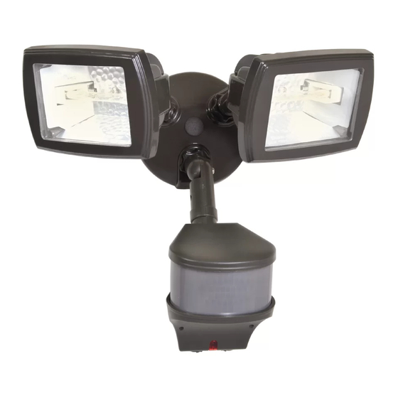
MS280D (Bronze)
MS280DW (White)
ENGLISH
ITEMS REQUIRED
(Purchase separately)
• Phillips screwdriver
• Outdoor weatherproof silicone caulking
HOW IT WORKS
PIR does a good job of detecting lateral motion across the 270°
range of detection. Precision Plus Doppler Radar™ does an
excellent job detecting motion towards and away from the unit.
Both systems combined provide enhanced accuracy and complete
coverage within the detection range. Motion from any direction will
trigger your floodlight—even during hot or cold temperature extremes.
WARNINGS AND CAUTIONS
• Read these instructions.
• Keep these instructions.
• Heed all warnings.
• Follow all instructions.
• For outdoor use only.
• cULus LISTED for wet locations.
• Connect fixture to a 120 volt, 60 Hz power source. Any other connection voids the warranty.
• Fixture should be installed by persons with experience in household wiring or by a qualified
electrician. The electrical system, and the method of electrically connecting the fixture to it,
must be in accordance with the National Electrical Code and local building codes.
• Always replace bulb with the same wattage or lower wattage than marked. Installing a bulb
of a higher wattage could create a fire hazard. Use of a higher wattage bulb will void the
warranty. (Maximum 150 watt halogen bulb.) To meet ENERGY STAR
maximum lamp wattage cannot exceed 250 watts.
• Keep away from flammable objects. Do not position fixture within two inches
of any combustible materials.
• Bulb gets HOT quickly!
• The bulb and fixture get extremely hot during use. Disconnect power and allow
fixture to cool before changing bulb or handling fixture.
• Disassembly of your fixture will void the warranty.
• Your fixture is pre-wired and pre-assembled for easy installation.
• Minimum 90° C supply conductors.
• Fixture should be mounted to a recessed or surface mounted standard grounded junction
box marked for use in wet locations.
• Do not allow sensor head to touch light housing – maintain at least 1/2 inch space between
fixture and sensor.
• If lens is replaced, use only tempered safety glass of equal thickness.
• For proper operation and protection against damage; the motion sensor head adjustment
knobs must be facing the ground.
Questions? / ¿Preguntas ? 1-800-334-6871 ConsumerProducts@cooperlighting.com
PACKAGING CONTENTS / CONTENIDO DEL PAQUETE
A. Motion detector
B. (3) Locknuts
and fixture
(3) Contratuercas
Detector de
movimiento y
artefacto de luz
E. Mounting bracket
Soporte de montaje
270 degrees
®
requirements,
C. (2) 100 watt light fixtures
(2) Portalámparas de
100 vatios
D. (2) 100 watt halogen
T-3 bulbs
(pre-installed)
(2) Focos halógenos
T-3 de 150 vatios
(preinstalado)
• For maximum bulb life, position fixture so the quartz halogen
bulb remains within 4 degrees of horizontal.
• Do not use this apparatus near water.
• Clean only with a dry cloth.
• Do not block any ventilation openings. Install in accordance
with the manufacturer's instructions.
• Do not install near any heat sources such as radiators, heat registers, stoves or other
Up to
apparatus (including amplifiers) that produce heat.
90 feet
• Only use attachments/accessories specified by the manufacturer.
• This device complies with Part 15 of the FCC Rules. Operation is subject to the following
two conditions: (1) This device may not cause harmful interference, and (2) this device must
accept any interference received, including interference that may cause undesired operation.
Under Part 15 of the FCC Rules, any changes or modifications to the motion detector
described in this instruction sheet that are not expressly approved by Cooper Lighting, LLC
could void the user's authority to operate the equipment.
NOTE: This equipment has been tested and found to comply with the limits for a Class B
digital device, pursuant to part 15 of the FCC Rules. These limits are designed to provide
reasonable protection against harmful interference in a residential installation. This equip-
ment generates, uses and can radiate radio frequency energy and if not installed and used in
accordance with the instructions, may cause harmful interference to radio communications.
However, there is no guarantee that interference will not occur in a particular installation. If
this equipment does cause harmful interference to radio or television reception, which can be
determined by turning the equipment off and on, the user is encouraged to try to correct the
interference by one or more of the following measures:
- R eorient or relocate the receiving antenna.
- I ncrease the separation between the equipment and receiver.
- C onnect the equipment into an outlet on a circuit different from that to which the receiver
is connected.
- C onsult the dealer or an experienced radio/TV technician for help.
WARNING: FCC Regulations state that any unauthorized changes or modifications
to this equipment not expressly approved by the manufacturer could void the user's
authorization to operate this equipment.
SAVE THESE INSTRUCTIONS.
FOR BEST RESULTS
• Install the motion sensor/transmitter 8-12 feet above
the ground. (Motion sensor is less sensitive above 12 feet.)
• Locate motion sensor so motion moves laterally or
towards the detection zone (Fig. 1).
• Locate sensor away from heat producing sources to
prevent false triggering. Also be very careful not to
include objects such as windows, white walls and
water in the detection zone.
• Locate sensor away from moving objects such as
trees, large shrubs and street traffic.
• Do not install more than one motion activated
floodlight on one wall switch.
1
Instruction Manual / Instrucciones
F. (2) #6 and (2) #8 mounting screws
(use the size that fits your junction box)
(2) Tornillos #6 y (2) tornillos #8 de montaje
(utilice el tamaño que mejor se adecue a
su caja de conexión)
G. Coverplate gasket
Junta de la placa
de cubierta
H. (3) Wire nuts
(3) Tuercas
para alambre
I. Mounting plate screw
Tornillo para la placa
de montaje
J. Color-matched
center hole plug
Tapón para agujero
central, de color
coincidente
K. Mounting hook
Gancho de
montaje
4˚
Fig. 1
Advertisement
Table of Contents

Related Manuals for Cooper Lighting MS280D


Summary of Contents for Cooper Lighting MS280D
- Page 1 K. Mounting hook para alambre (2) Focos halógenos Gancho de T-3 de 150 vatios montaje (preinstalado) I. Mounting plate screw E. Mounting bracket MS280D (Bronze) Tornillo para la placa Soporte de montaje MS280DW (White) de montaje • For maximum bulb life, position fixture so the quartz halogen ENGLISH bulb remains within 4 degrees of horizontal. 4˚...
- Page 2 MOUNTING AND WIRING YOUR FIXTURE settings. Each location will be different and your terrain may affect the angle your sensor needs. Adjusting the Fig. 2 NOTE: Universal coverplate mounts to recessed or angle will change your area of detection. Here are some surface mounted standard junction boxes (Fig. 2). 1-1/2˝ 1-1/2˝ general guidelines to help with setup: Junction box must be at least 1-1/2˝ in depth for proper • 8´-12´ above the ground is a good range for the installation for recessed mount application. placement of your fixture. NOTE: For best performance when installing more than • For an 8´ mounting height, placing the sensor at a Fig. 9 one Precision Plus Doppler Radar™ fixture: 5° angle below horizontal should work well for Round Octagonal • Two or more units mounted side by side (facing the most locations (Fig. 9). same direction) should be at least 17 feet apart. • If the fixture is mounted higher, the angle of the • Two units facing each other should be mounted at sensor below horizontal should increase. 5° least 100 feet apart. 5. Walk through the detection zone at the farthest • Fixture can be wall or eave mounted (Fig. 3). Fig. 3 distance you want your detector to detect motion. WARNING: Risk of electric shock. Disconnect 6. Adjust the SENSITIVITY knob until you get desired power at fuse or circuit breaker before installing results. For more range, aim sensor slightly upward.
- Page 3 2-YEAR LIMITED WARRANTY Mode of MODE Knob How to Set THE FOLLOWING WARRANTY IS EXCLUSIVE AND IN LIEU OF ALL OTHER WARRANTIES, Operation Adjustment Power Switch WHETHER EXPRESS, IMPLIED OR STATUTORY INCLUDING, BUT NOT LIMITED TO, ANY Return to “Auto” MODE knob arrow Turn the power OFF WARRANTY OF MERCHANTABILITY OR FITNESS FOR ANY PARTICULAR PURPOSE. Motion Activated Setting points to a time selection for at least 90 seconds Cooper Lighting, LLC (“Cooper Lighting”) warrants to customers that, for a period of two years from any of within the 1m-12m and then back ON. from the date of purchase, Cooper Lighting’s products will be free from defects in materials the above settings. time range. and workmanship. The obligation of Cooper Lighting under this warranty is expressly limited to the provision of replacement products. This warranty is extended only to the original ENERGY STAR ®...
- Page 4 NOTA: Para obtener los mejores resultados cuando • Manténgalo alejado de objetos inflamables. No coloque el artefacto en posición dentro de dos pulgadas (5 cm) de cualquier material combustible. instale más de un accesorio Radar Doppler Precision Plus™: • ¡La bombilla se CALIENTA rápidamente! • Dos o más unidades montadas de lado a lado • La lámpara y el artefacto se calientan extremadamente durante el uso. (dirigidas a la misma dirección) deben estar Antes de intentar reposicionar el artefacto, deje que se enfríe totalmente. separadas a 17´ (5,2 m) de distancia. • Si desarma el artefacto, se anula la garantía. • Dos unidades, una frente a la otra, deben montarse • La lámpara es percableada para facilitar la instalación. a 100´ (30,5 m) de distancia. Fig. 3 • Utilice conductores de suministro que soporten un mínimo de 90°C. • El accesorio puede ser montado en la pared o el • Instale el artefacto sobre una caja eléctrica empotrada o superficial con conexión a tierra alero (Fig. 3). marcada para usar en lugares húmedos. ADVERTENCIA: Riesgo de choque eléctrico. Antes • No permita que la cabeza del detector toque el alojamiento de la lámpara - mantenga por de la instalación o reparación, desconecte la lo menos 1/2˝ (1,27 cm) de espacio entre el accesorio y el detector.
- Page 5 SELECCIONE LA FUNCIÓN DESEADA 4. Dirija el detector hacia la dirección donde se espera que haya movimiento. Mantenga por lo menos 1˝ Modo de Adjuste de la perilla Como adjustar (2,54 cm) de espacio entre la cabeza del detector y funcionamiento de MODO interruptor electrico las lámparas. Posicione siempre la cabeza del detector con los interruptores de control apuntando Ajuste de Prueba Ajuste de interruptor La perilla de MODO hacia el suelo. de pared Las luces deben encenderse apunta hacia la TEST. NOTA: (Colocación de la cabeza del detector) Para (conectado al accesorio) por el movimiento tanto en el día una óptima detección, tendrá que experimentar con el...
- Page 6 Todos los productos devueltos deben estar acompañados por un Número de autorización Problema Causa Posible / Acción Correctiva de productos devueltos emitido por la compañía y deben devolverse con flete prepagado. Se rechazará todo producto recibido sin un Número de autorización de productos devueltos Las Luces Se Hay movimiento en la zona de detección. desde la compañía. Encienden Durante • Asegúrese de que el sensor no esté reaccionando a objetos Cooper Lighting, LLC no se hace responsable por la mercancía dañada durante el transporte. móviles tales como árboles, tráfico, etc. La Noche Y No Se Los productos reparados o reemplazados estarán sujetos a los términos de esta garantía • Si este es el caso, disminuya la sensibilidad. Apagan y se inspeccionan al ser empacados. El daño evidente y oculto que se provoque durante el • Cambie la posición del sensor de movimiento. transporte se debe informar de inmediato al transportista que realiza la entrega y se debe La unidad está en modo de anulación (si no hay movimiento). presentar un reclamo. • Ponga el interruptor de la luz en “OFF” durante 90 segundos La reproducción de este documento sin la aprobación previa por escrito de Cooper Lighting, LLC está estrictamente prohibida. y vuel va a colocarlo en “ON”. Esto colocará de nuevo la unidad Para solicitar ayuda, llame al 1-800-334-6871 o envíe un correo electrónico a ConsumerProducts@cooperlighting.com en la modalidad “Auto” (automático).
Need help?
Do you have a question about the MS280D and is the answer not in the manual?
Questions and answers