Table of Contents
Advertisement
Available languages
Available languages
Quick Links
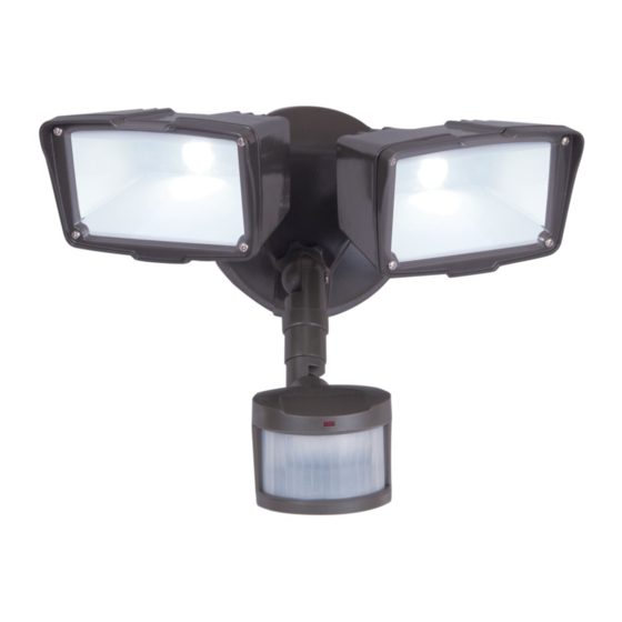
MST27920LES
(Bronze /Bronce)
ENGLISH
ITEMS REQUIRED
(Purchase separately)
• Phillips screwdriver
• Outdoor weatherproof silicone caulking
IMPORTANT SAFETY INSTRUCTIONS
When using product, basic precautions should always be followed, including the following:
• Heed all warnings, including below warnings AND those included on product.
• Save these instructions and warnings.
• For outdoor use only.
• cULus LISTED for wet location.
• Disassembling your fixture will void the warranty.
• Your fixture is prewired and preassembled for easy installation.
WARNING
• Read and follow these instructions.
• Risk of fire/electric shock. If not qualified, consult an electrician.
• Disconnect power at fuse or circuit breaker before installing or servicing.
CAUTION
• Connect fixture to a 120 volt, 60 Hz power source. Any other connection voids
the warranty.
• Fixture should be installed by persons with experience in household wiring or by a
qualified electrician. The electrical system, and the method of electrically connecting
the fixture to it, must be in accordance with the National Electrical Code and local
building codes.
• Mount fixture to a grounded, recessed-mounted standard junction box marked for use
in wet locations.
• Suitable for wall mount or eave mount only. NOT suitable for ground mount installation.
• For proper operation and protection against damage, the motion sensor head
adjustment knobs must be facing the ground.
• Do not mount below 5 feet.
• This device complies with Part 15 of the FCC Rules. Operation is subject to the
following two conditions: (1) This device may not cause harmful interference, and (2)
this device must accept any interference received, including interference that may cause
undesired operation. Under Part 15 of the FCC Rules, any changes or modifications to
the motion detector described in this instruction sheet that are not expressly approved
by Cooper Lighting, LLC could void the user's authority to operate the equipment.
NOTE: This equipment has been tested and found to comply with the limits for
a Class B digital device, pursuant to Part 15 of the FCC Rules. These limits are
designed to provide reasonable protection against harmful interference in a
Questions? / ¿Preguntas ? 1-800-334-6871 ConsumerProducts@cooperlighting.com
PACKAGING CONTENTS / CONTENIDO DEL PAQUETE
A. Motion detector
B. Mounting bracket
and light fixture
Soporte de montaje
Detector de
movimiento y
artefacto de luz
E. (3) Wire nuts
(3) Tuercas
para alambre
C. Gasket
D. (2) #6-32 x 3/4 in. and (2) #8-32 x 3/4 in. junction box screws
(use the size that fits your junction box)
Junta
(2) Tornillos #6-32 x 3/4 pulg. y (2) tornillos #8-32 x 3/4 pulg.
para montaje de la caja de conexiónes (utilice el tamaño que
mejor se adecue a su caja de conexiónes)
F. (2) #8-32 x 1-1/4 in. cover
mounting screws
(2) Tornillos #8-32 x 1-1/4 pulg.
de montaje de la cubierta
residential installation. This equipment generates, uses and can radiate radio
frequency energy and if not installed and used in accordance with the instructions,
may cause harmful interference to radio communications. However, there is no
guarantee that interference will not occur in a particular installation. If this
equipment does cause harmful interference to radio or television reception, which
can be determined by turning the equipment off and on, the user is encouraged to
try to correct the interference by one or more of the following measures:
- Reorient or relocate the receiving antenna.
- Increase the separation between the equipment and receiver.
- Connect the equipment into an outlet on a circuit different from that to which the
receiver is connected.
- Consult the dealer or an experienced radio/TV technician for help.
WARNING: FCC Regulations state that
any unauthorized changes or modifications
to this equipment not expressly approved by
the manufacturer could void the user's
authorization to operate this equipment.
SAVE THESE INSTRUCTIONS.
FOR BEST RESULTS
• Install the motion sensor/transmitter 8-12 feet
above the ground. (Motion sensor is less sensitive
above 12 feet.)
• Locate motion sensor so motion moves across
detection zone (Fig. 1).
• Locate sensor away from heat producing sources to
prevent false triggering. Also be very careful not to
include objects such as windows, white walls and
water in the detection zone.
• Locate sensor away from moving objects such as
trees, large shrubs and street traffic.
• Do not install more than one motion activated
floodlight on one wall switch.
MOUNTING AND WIRING YOUR FIXTURE
WARNING: Risk of electric shock. Disconnect
power at fuse or circuit breaker before installing
or servicing.
NOTE: Fixture can be wall or eave mounted (Fig. 2).
NOTE: Coverplate mounts to recessed mounted
standard junction boxes (Fig. 3). Junction box must be
at least 1-1/2 inch in depth for proper installation for
recessed mount application.
1
Instruction Manual / Instrucciones
G. (2) Decorative screw cover caps
(2) Cubiertas tapatornillos decorativas
1
2
Wall mount
Eave mount
3
1-1/2 in.
Round
1-1/2 in.
Octagonal
Advertisement
Table of Contents

Related Manuals for Cooper Lighting all-pro mst27920les


Summary of Contents for Cooper Lighting all-pro mst27920les
- Page 1 Cooper Lighting, LLC could void the user’s authority to operate the equipment. NOTE: This equipment has been tested and found to comply with the limits for a Class B digital device, pursuant to Part 15 of the FCC Rules.
- Page 2 SELECTING YOUR DESIRED FEATURE 1. Line up the holes on the mounting bracket (B) with the holes on your junction box. Using either (2) #6 Mode of MODE Knob How to Set screws or (2) #8 screws (D) (depending on size of Operation Adjustment Power Switch...
- Page 3 • Este dispositivo cumple con la Parte 15 de las Reglas de la Comisión Federal de years from the date of purchase, Cooper Lighting’s products will be free from defects in Comunicaciones (FCC) de los E. U. de A. La operación está sujeta a las dos condiciones materials and workmanship.
- Page 4 SELECCIONE LA FUNCIÓN DESEADA 2. Pase los cables del artefacto a través de la junta de la placa de cubierta (C) (Fig. 5). Modo de Adjuste de la perilla Como adjustar funcionamiento de MODO interruptor electrico Ajuste Automático La flecha de la perilla apunta Mantenga la (activado por movimiento) al ajuste de tiempo deseado...
- Page 5 La reproducción de este documento sin la aprobación previa por escrito de Cooper Lighting, LLC está estrictamente prohibida. Para solicitar ayuda, llame al 1-800-334-6871 o envíe un correo electrónico a ConsumerProducts@cooperlighting.com.
Need help?
Do you have a question about the all-pro mst27920les and is the answer not in the manual?
Questions and answers