Table of Contents
Advertisement
Quick Links
Advertisement
Table of Contents

Related Manuals for APART ZONE4


Summary of Contents for APART ZONE4
- Page 1 ZONE4 Instruction manual...
- Page 3 ZONE4 Instruction manual ZONE4 Manual...
-
Page 4: Safety Information
Pre-Amplifiers Safety information • Please check the carton box for any kind of damage on reception of the goods. In case of a damaged carton, please contact your dealer before opening the carton. • !!!! Danger !!!! Exposure to extremely high noise levels may cause a permanent hearing loss. - Page 5 ZONE4 Instruction manual • Do not connect the inputs / outputs of amplifiers or consoles to any other voltage source, such as a battery, mains source, or power supply, regardless of whether the amplifier or console is turned on or off.
- Page 6 Finally there is the IR input port. This port can be used to connect our optional PIR-REC infrared receiver. There is no infrared remote control available for the ZONE4 unit. We have added the infrared codes for those who want to program their universal infrared...
-
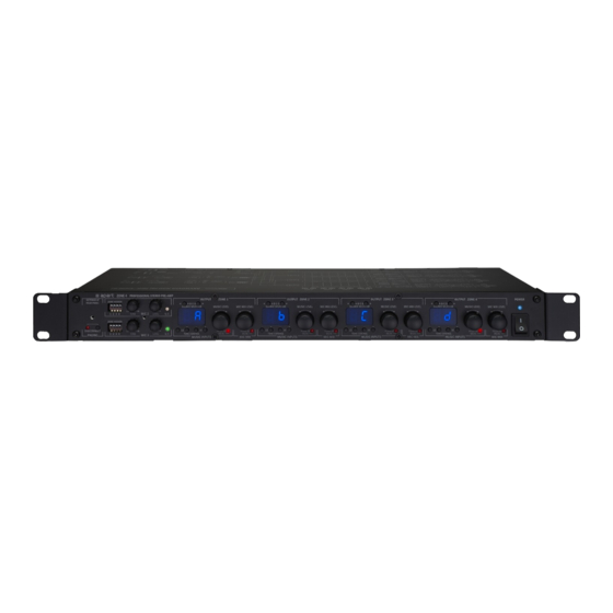
Page 7: Front Panel
ZONE4 Instruction manual Front panel 15 17 16 18 1. Disconnect paging led: this led is lit when you push the disconnect paging button ‘2’. 2. Disconnect paging button: push this button to disable the paging function. This can be convenient in case you want to avoid accidental paging and thus muting of the line inputs. - Page 8 Pre-Amplifiers level or to the left to reduce the level. 8. Mic 3 level control: turn the knob to the right to increase mic 3 level or to the left to reduce the level. 9. Mic signal/clip led: this led is green when a signal is present on mic 2 input and is red when the input is overloaded.
- Page 9 ZONE4 Instruction manual 16. Music mute led: this led lights up when the music in zone 1 is muted by pushing the ‘15’ knob or by activating paging. 17. Mic mix level control zone 1: turn this knob to adjust the zone 1 mic mix level.
-
Page 10: Back Panel
Zone 4 remote wall panels only. Never connect this to a computer or other network. Damage caused by poor or incorrect installation is excluded from the warranty. Up to 8 pcs. ZONE4R remote panels can be connected to a single ZONE4. - Page 11 ZONE4 Instruction manual More than 1 panel per zone can be used. Please refer to the ZONE4R manual. 7. Same as described in 6. 8. Same as described in 6. 9. Same as described in 6. 10. Output mode selector switch: here you can configure the individual zone outputs for mono or stereo operation.
- Page 12 MICPAT-4 selective paging station. 29. RJ45 connector for the MICPAT-4 selective paging station only. Up to 4 pcs. of MICPAT-4 can be connected to a single ZONE4. A smart bus-sytem arranges the Priority (busy-line). Please refer to the MICPAT4 manual.
- Page 13 ZONE4 Instruction manual ZONE4 INFRARED CONTROL CODES* IR FUNCTIONS ZONE LEAD DEVICE ID DATA CODE CODE CODE MUSIC VOLUME UP ZONE 1 04FB MUSIC VOLUME DOWN ZONE 1 04FB MIC VOLUME UP ZONE 1 04FB MIC VOLUME DOWN ZONE 1...
- Page 14 Pre-Amplifiers Select source B ZONE 3 04FB Select source C ZONE 3 04FB Select source D ZONE 3 04FB Music volume UP ZONE 4 04FB Music volume down ZONE 4 04FB Mic volume up ZONE 4 04FB Mic volume down ZONE 4 04FB Select source A...
- Page 15 04FB Disconnect paging (on) 04FB Connect paging (off) 04FB Source up ZONE 1 04FB Source up ZONE 2 04FB Source up ZONE 3 04FB Source up ZONE 4 04FB Command structure : ZONE4 ID code –> command –> inverse command.
-
Page 16: Technical Specifications
Pre-Amplifiers TECHNICAL SPECIFICATIONS Outputs Output stereo zone 1 unbalanced Cinch connector 0dB, 1 V, 100 ohm Output stereo zone 2 unbalanced Cinch connector 0dB, 1 V, 100 ohm Output stereo zone 3 unbalanced Cinch connector 0dB, 1 V, 100 ohm Output stereo zone 4 unbalanced Cinch connector 0dB, 1 V, 100 ohm Frequency response... - Page 17 ZONE4 Instruction manual Input mic/line 1 max input level -43 dBV / 18 dBV Input mic/line 2 and 3 Balanced on euroblock connectors Input mic/line 2 and 3 sensitivity Trim from 1,5mV / -56 dBV TO 150 mV / -16 dBV...
-
Page 18: Block Diagram
Pre-Amplifiers Block diagram... - Page 19 ZONE4 Instruction manual...
- Page 20 Audioprof nv Industriepark Brechtsebaan 8 bus 1 2900 Schoten - Belgium Company names, product names and trademarks are property of their respective owners. Apart-Audio specifications are subject to change without notice.
Need help?
Do you have a question about the ZONE4 and is the answer not in the manual?
Questions and answers