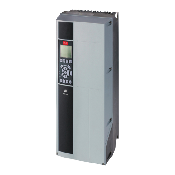
Danfoss VLT HVAC Drive FC 102 Operating Manual
Safe torque of, frequency converters
Hide thumbs
Also See for VLT HVAC Drive FC 102:
- Installation manual ,
- Programming manual (756 pages) ,
- Design manual (254 pages)
Summary of Contents for Danfoss VLT HVAC Drive FC 102
- Page 1 ENGINEERING TOMORROW Operating Guide Safe Torque Off ® Frequency Converters vlt-drives.danfoss.com...
-
Page 3: Table Of Contents
4.3 Parameter Settings for STO in Combination with VLT PTC Thermistor Card MCB 112 4.4 Automatic/Manual Restart Behavior 4.5 STO Commissioning Test 4.6 System Configuration Security 4.7 Service and Maintenance 5 STO Technical Data Index MG37D502 Danfoss A/S © 01/2018 All rights reserved. -
Page 4: Introduction
1 Introduction 1.3.2 Products Covered and Identification 1.1 Purpose of the Manual ® This manual provides information for use of Danfoss VLT The STO function is available for the following types of frequency converters in functional safety applications. The frequency converters: •... -
Page 5: Symbols, Abbreviations, And Conventions
Parameter option. • Alarms/warnings. All dimensions in drawings are given in both metric and imperial units (in brackets), for example: mm (in). An asterisk (*) indicates the default setting of a parameter. MG37D502 Danfoss A/S © 01/2018 All rights reserved. -
Page 6: Safety
Other subsystems and the validity of signals and Emergency-Off requires measures of electrical isolation, commands from them. for example by switching off mains via an additional • Designing appropriate safety-related control contactor. systems (hardware, software, parameterization, and so on). Danfoss A/S © 01/2018 All rights reserved. MG37D502... - Page 7 • A presence in the dangerous zone can be categories, refer to EN 60204-1. physically excluded when STO is not activated. In particular, paragraph 6.3.3.2.5 of ISO 12100: 2010 must be observed. MG37D502 Danfoss A/S © 01/2018 All rights reserved.
-
Page 8: Installation
Category 3 /PL “d” (ISO 13849-1) or SIL 2 (EN 62061 and IEC 61508). Illustration 3.1 Jumper between Terminals 12/13 (24 V) and 37 (all Frequency Converters except of FCD 302) Danfoss A/S © 01/2018 All rights reserved. MG37D502... -
Page 9: Installation In Combination With Vlt Ptc Thermistor Card Mcb 112
5-19 Terminal 37 Safe Stop can be set to value [7] ® PTC 1 & Relay W or [8] PTC 1 & Relay A/W. Refer to VLT Thermistor Card MCB 112 Operating Instructions for further details. MG37D502 Danfoss A/S © 01/2018 All rights reserved. -
Page 10: Commissioning
• Do not select [4] PTC 1 Alarm and [5] PTC 1 Warning when an external safety device is used. Only use those selections when only MCB 112 uses the STO. Danfoss A/S © 01/2018 All rights reserved. MG37D502... -
Page 11: Sto Commissioning Test
Send reset signal (via bus, digital I/O, or [Reset] key). Ensure that the motor becomes operational again. The commissioning test is successfully completed when all the given steps are passed. MG37D502 Danfoss A/S © 01/2018 All rights reserved. -
Page 12: Service And Maintenance
Reconnect the 24 V DC voltage supply to terminal 37. Verify that the motor is not started automatically and restarts only by giving a reset signal (via bus, digital I/O, or [Reset] key). Danfoss A/S © 01/2018 All rights reserved. MG37D502... -
Page 13: Sto Technical Data
Parallel Drive Modules: • 400 V: 250/315 kW (350/450 hp) - 800/1000 kW (1200/1350 hp) (High Overload/Normal Overload). • 690 V: 315/400 kW (350/400 hp) – 1000/1200 kW (1150/1350 hp) (High Overload/Normal Overload). MG37D502 Danfoss A/S © 01/2018 All rights reserved. - Page 14 Functional safety data are available from a data library for use with the SISTEMA calculation tool from the IFA (Institute for Occupational Safety and Health of the German Social Accident Insurance), and data for manual calculation. SISTEMA is available for download at www.drives.danfoss.com/services/pc-tools/. Danfoss A/S © 01/2018 All rights reserved. MG37D502...
-
Page 15: Index
Output......................7 Parameter settings.................. 8 Products covered..................2 Qualified personnel................4 Restart behavior..................8 Restart prevention................8, 9 Safety device..................... 7 Safety-guard switch................7 Safety-related sensor................7 Selections....................8 Signal...................... 4, 7 MG37D502 Danfoss A/S © 01/2018 All rights reserved. - Page 16 Danfoss can accept no responsibility for possible errors in catalogues, brochures and other printed material. Danfoss reserves the right to alter its products without notice. This also applies to products already on order provided that such alterations can be made without subsequential changes being necessary in specifications already agreed. All trademarks in this material are property of the respective companies.


Need help?
Do you have a question about the VLT HVAC Drive FC 102 and is the answer not in the manual?
Questions and answers