Danfoss VLT FC 102, VLT FC 103, VLT FC 202, VLT FC 301 Manual
- Programming manual (756 pages) ,
- Design manual (254 pages) ,
- Operating manual (200 pages)
Advertisement
Qualified Personnel
Only qualified personnel are allowed to install, commission, and maintain Danfoss drives. Qualified personnel are trained individuals who are familiar with and authorized to mount and wire the drive in accordance with pertinent laws and regulations. Also, qualified personnel must be familiar with the instructions and safety measures described in this installation guide.
Safety Symbols
The following symbols are used in this guide:

Indicates a hazardous situation which, if not avoided, will result in death or serious injury.

Indicates a hazardous situation which, if not avoided, could result in death or serious injury.

Indicates a hazardous situation which, if not avoided, could result in minor or moderate injury.
NOTICE
Indicates information considered important, but not hazard-related (for example, messages relating to property damage).
Required Tools
- Lifting aid
- Tape measure
- Drill with assorted bits
- Screwdrivers (Torx, Phillips, slotted)
- Wrench with 7–17 mm sockets
- Socket extensions
- Sheet metal punch and/or pliers
- Wire crimper
Verifying the Shipment and Its Contents

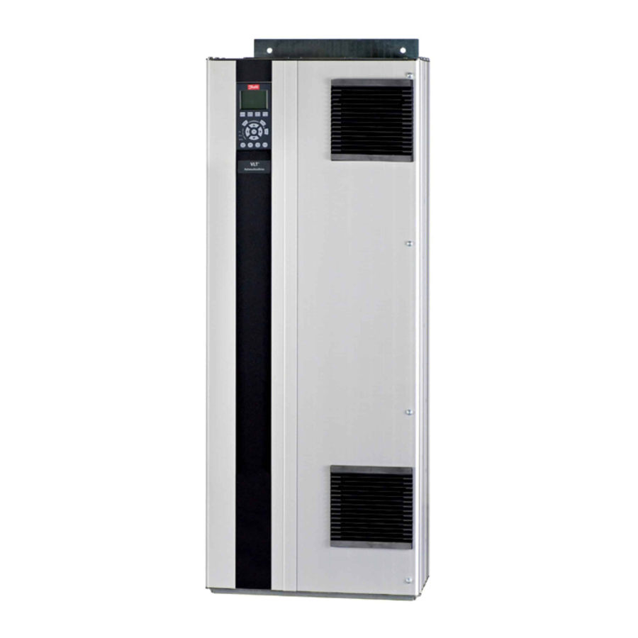
Verify the items supplied and the information on the product label match the order. The product label is on the exterior of the drive. See Figure 1.
- Type code
- Part number and serial number
- Power rating
- Input/output voltage, frequency, and current
- Enclosure protection rating
- Enclosure size
EMC-compliant Installation
For more information, refer to the operating or design guide.
- Use shielded cables for motor output (unshielded cables in metal conduit are acceptable), brake, DC, and control wiring.
- Ensure that motor, brake, and DC cables are as short as possible to reduce the interference level from the entire system. Provide a minimum space of 200 mm (7.9 in) between mains input, motor cables, and control cables.
- Convey the currents back to the drive using a metal mounting plate and proper EMC bonding clamps. Ensure good electrical contact from the mounting plate through the mounting screws to the metal frame of the enclosure.
- If the shield connection points have a voltage potential difference, connect a low impedance equalizing wire parallel to the shielded cable.
- When using relays, control cables, a signal interface, fieldbus, or brake, connect the shield to the enclosure at both ends. If the ground path has high impedance, is noisy, or is carrying current, break the shield connection on one end to avoid ground current loops.
Installing the Drive

SHOCK HAZARD
Touching an uncovered motor, mains, or DC connection plug or terminal can result in death or serious injury.
- All plugs and terminal protection covers for the motor, mains, and DC connections must be installed within the IP20 enclosure to provide an IP20 protection rating. If plug and terminal covers are not installed, the protection rating is considered IP00.
The installation location is important. Full output current is available when the following installation conditions are met. For temperatures and altitudes outside this range, consult the Derating sections in the product-specific design guide.
- Maximum ambient temperature: 45 ºC (113 ºF) average over 24 hours and 50 ºC (122 ºF) for 1 hour.
- Minimum ambient temperature: 0 ºC (32 ºF).
- Altitude < 1000 m (3280 ft) above sea level.
- Identify the enclosure size. See Illustration 1.

- Identify any options that need extra wiring and setup by using the type code. See step 1 in the Illustrations section.
Scanning the QR code on the cover opens the documentation search page. Use the option number to search for related documentation. For example, use MCA 120 to search for VLT PROFINET MCA 120 documentation. - Make sure that the operating environment and electrical installation meet the following standards.
- Indoor unconditioned/pollution degree 2.
- Overvoltage category 3.
- Review the wiring diagram. See step 2.

All wiring must comply with local and national regulations regarding cross-section and ambient temperature requirements. Loose connections can cause equipment faults or reduced performance. Tighten the terminals according to the proper torque value shown in step 9 in the Illustrations section. - Review the fuse specifications. See step 3.

The drive can be suitable for use on a circuit capable of delivering up to 100 kA short circuit current rating (SCCR) at 480/600 V. For circuit breaker and switch SCCR ratings, see the product-specific design guide. - Review the power cable specifications. See step 4.


Use copper wire with a minimum 70 ºC (158 ºF) rating. For aluminum wire, see the product-specific design guide. - Install the drive following the numbered steps in the Illustrations section. Certain illustrations/steps pertain to specific enclosure sizes and are marked as such.
- Attach accessory bag components to the drive. See step 5.


- Mount the drive on or against a solid, non-combustible mounting surface such as concrete or metal. Ensure proper cooling by providing minimum clearance above and below the drive. See step 6.


- D3h–D4h are wall mounted, D1h–D2h and D5h–D6h are wall or floor mounted, and D7h–D8h are floor mounted.
- Create cable openings in the cable entry plate. See step 7.

- Install the control wiring. See step 8.

- Install the motor, mains, and ground wiring. See step 9.


![]()

- Route the control cables towards the left side of the drive.
- Attach accessory bag components to the drive. See step 5.
- Securely fasten the cover to the drive.
- Perform initial drive and motor setup. Consult the product-specific programming guide.
Functional safety options require extra wiring and parameter configuration. See the specific functional safety operating guide, such as the Safe Torque Off Operating Guide, for more information on installing the safety option.


Fire/Emergency Mode
When running in fire/emergency mode, the frequency converter can be programmed to sacrifice itself so the applications (for example, ventilation or water pumps) continue to operate as long as possible.
Before activating the fire/emergency mode, ensure that all relevant parameters for the motor and application are configured correctly. Danfoss recommends running the application from minimum to maximum speed and then bringing the application to a complete stop to verify that it functions correctly without triggering any warnings or alarms on the local control panel. Failure to complete this step before enabling the fire/emergency mode can result in loss of warranty. For more instructions on configuring the fire/emergency mode, see Parameter Group 24-** Application Functions 2 in the VLT programming guide, or contact your local Danfoss office.
Power Losses and Efficiency
For power loss data including part load losses, see https://ecosmart.mydrive.danfoss.com.
Safety Precautions
LACK OF SAFETY AWARENESS
Before starting installation, read all safety guidelines and precautions in this installation guide. Additional documentation such as the product-specific operating guide, design guide, and programming guide, as well as the functional safety guides can be accessed by scanning the QR code on the front cover. PC tools and MyDrive ecoSmart can be downloaded at www.danfoss.com.
This guide gives important information on preventing injury and damage to the equipment or the system. Ignoring this information can lead to death, serious injury, or severe damage to the equipment.
- Make sure to fully understand the dangers and safety measures present in the application.
- Before performing any electrical work on the drive, lock out and tag out all power sources to the drive.
LIFTING HEAVY LOAD
The drive is heavy. Lifting heavy objects incorrectly can result in death, injury, or property damage.
- Follow local safety regulations on lifting.
- Check the weight of the drive. The weight is provided on the outside of the shipping box.
- If lifting equipment is used, ensure that it is in proper working condition and can safely lift the weight of the drive.
- Test lift the drive to verify the proper center of gravity. Reposition the lifting point if not level.
HAZARDOUS VOLTAGE
Drives contain hazardous voltage when connected to AC or DC supply. Failure to perform installation, startup, and maintenance by qualified personnel can result in death or serious injury.
- Only qualified personnel must perform installation, startup, and maintenance.
DISCHARGE TIME
The drive contains DC-link capacitors, which can remain charged even when the drive is not powered. High voltage can be present even when the warning indicator lights are off. Failure to wait the specified time after power has been removed before performing service or repair work can result in death or serious injury.
- Stop the motor
- Disconnect all power sources, including permanent magnet type motors.
- Wait for capacitors to discharge fully. The discharge time is specified on the drive product label.
- Measure the voltage level to verify full discharge.
UNINTENDED START
When the drive is connected to the AC mains or connected on the DC terminals, the motor may start at any time, causing risk of death, serious injury, and equipment or property damage.
- Stop the drive and motor before configuring parameters.
- Make sure that the drive cannot be started by external switch, a fieldbus command, an input reference signal from the control panel, or after a cleared fault condition.
- Disconnect the drive from the mains whenever safety considerations make it necessary to avoid unintended motor start.
- Check that the drive, motor, and any driven equipment are in operational readiness.
INTERNAL FAILURE HAZARD
An internal failure in the drive can result in serious injury when the drive is not properly closed.
- Ensure that all safety covers are in place and securely fastened before applying power.

ELECTRICAL SHOCK AND FIRE HAZARD
The drive can cause a DC current in the ground conductor. Failure to use a Type B residual current-operated protective device (RCD) can lead to the RCD not providing the intended protection which can result in death, fire, or other serious hazard.
- Use an RCD device.
- When an RCD is used for protection against electrical shock or fire, use only a Type B device on the supply side.
INDUCED VOLTAGE
Induced voltage from output motor cables that run together can charge equipment capacitors, even with the equipment turned off and locked out/tagged out. Failure to run output motor cables separately, or to use shielded cables, could result in death or serious injury.
- Run output motor cables separately or use shielded cables.
- Simultaneously lock out/tag out all the drives.
ELECTRICAL SHOCK HAZARD
Due to the stray capacitance of the shielded motor cable, the leakage currents exceed 3.5 mA. Failure to properly ground the drive can result in death or serious injury.
- Ensure that minimum size of the ground conductor complies with the local safety regulations for high touch current equipment.
- Use a reinforced ground conductor according to IEC 60364-5-54 cl. 543.7 or local safety regulations for equipment with leakage current >3.5 mA.
- For reinforced grounding:
Use a ground conductor with a cross-section of at least 10 mm2 (8 AWG) Cu or 16 mm2 (6 AWG) Al, or an extra ground conductor of the same cross-sectional area as the original ground conductor as specified by IEC 60364-5-54, with a minimum cross-sectional area of 2.5 mm2 (14 AWG) mechanically protected or 4 mm2 (12 AWG) not mechanically protected.
Use a ground conductor inside an enclosure or otherwise protected throughout its length against mechanical damage.
Use a ground conductor that is part of a multi-conductor power cable with a minimum PE conductor cross-section of 2.5 mm 2 (14 AWG) that is permanently connected or plugged in by an industrial connector. The multi-conductor power cable must be installed with an appropriate strain relief.
THERMISTOR INSULATION
Risk of personal injury or equipment damage.
- To meet the PELV insulation requirements, use only thermistors with reinforced or double insulation.
NOTICE
EXCESSIVE HEAT AND PROPERTY DAMAGE
Overcurrent can generate excessive heat within the drive. Failure to provide overcurrent protection can result in risk of fire and property damage.
- Additional protective devices such as short-circuit protection or motor thermal protection between drive and motor is required for applications with multiple motors.
- Input fusing is required to provide short-circuit and overcurrent protection. If fuses are not factory-supplied, the installer must provide them. Refer to the product-specific documentation for fuse specifications.
NOTICE
PROPERTY DAMAGE
Protection against motor overload is not active by default. Failure to set the ETR function means that motor overload protection is not provided and property damage can occur if the motor overheats.
- To provide class 20 motor overload protection, enable the ETR function. See the programming guide for more information.
Documents / Resources
References
Download manual
Here you can download full pdf version of manual, it may contain additional safety instructions, warranty information, FCC rules, etc.
Download Danfoss VLT FC 102, VLT FC 103, VLT FC 202, VLT FC 301 Manual
Advertisement


Need help?
Do you have a question about the VLT FC 102 and is the answer not in the manual?
Questions and answers