Table of Contents
Advertisement
INSTALLATION and OPERATING
INSTRUCTIONS
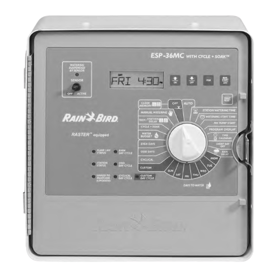
Controller Unit ESP-MC
Introduction
Welcome to Rain Bird! Thank you for purchasing your new, state-of-the-art Rain Bird
controller. For more than six decades, Rain Bird has led the irrigation industry in meet-
ing all of your water management needs by providing the highest quality products and
services available. Your new Rain Bird controller is designed to give you a lifetime of
on-site watering control.
1
Advertisement
Table of Contents

Subscribe to Our Youtube Channel
Related Manuals for Rain Bird ESP-MC


Summary of Contents for Rain Bird ESP-MC
- Page 1 Welcome to Rain Bird! Thank you for purchasing your new, state-of-the-art Rain Bird controller. For more than six decades, Rain Bird has led the irrigation industry in meet- ing all of your water management needs by providing the highest quality products and services available.
-
Page 2: The Esp-Mc Controller
MAXICOM interface board (MIB) for the ESP-MC. Special Features The ESP-MC is available as a wall-mount (WM) model in 8, 12, 16, 24, 32, or 40 sta- tion capability. For information about pedestals, contact your Rain Bird distributor. All ESP-MC models have the following special features: •... -
Page 3: Chapter 1: Installation
Chapter 1: Installation This section of the manual explains how to mount your new ESP-MC controller on the wall and how to connect the wiring. Mounting the Controller Before You Begin Important: Before installing your controller, make sure that the area around you is free from dirt and dust and that your hands and arms are clean. -
Page 4: Typical Wall-Mount Installation
Typical Wall-mount Installation 14” (36 cm) 11-1/4” minimum (28.8 cm) Cabinet is 6-5/8” (17 cm) 11-3/8” (28.2 cm) To Fuse 120 Volt AC Locate for Wiring in Conduit easy access and for comfortable Wall Floor Valve Wiring in Conduit... -
Page 5: Mounting The Controller On The Wall
Chapter 1: Installation (Continued) Removing the Controller’s Faceplate In order to mount the controller, you must first remove the faceplate. To do so: 1. Remove the controller cabinet door from its two hinges by opening the door then holding the bottom of the door and sliding up. 2. -
Page 6: Connecting The Controller
Important: All wiring must be installed and connected in accordance with local codes. Connections to the Field Valves Each valve that is controlled by the ESP-MC must have its own wire that is connected to a numbered station terminal on the controller’s terminal strip. Each station terminal is capable of operating two valves. - Page 7 To connect the valve wires: 1. Feed each valve wire up through the large hole on the bottom of the controller cabi- net. 2. Strip 1/2” (1.3 cm) from the end of the valve wire. Insert the wire into the appropriate station terminal.
-
Page 8: Grounding Connections
Grounding Connections The ESP-MC is equipped with built-in electrical surge protection. For this system to function, the earth ground terminal on the controller must be connected to a ground rod that is driven into the earth. Important: Use a #10 (6 mm) or #8 (10 mm) bare wire to connect the controller to the ground-rod. - Page 9 Main Power Wire Connections: Connections to an Optional Sensor The ESP-MC controller allows you to connect an optional sensor. The ESP-MC works with any open or closed switch sensor such as the Rain Bird Raincheck. Important: The wires you use to connect the controller to the sensor must be ap- proved for underground use.
- Page 10 9 volt battery supplied. Then push the battery into the bat- tery holder. The ESP-MC fully charges the nickel metal hydride, 9 volt battery in about 48 hours and continues to charge the battery whenever the controller is supplied with power.
-
Page 11: Chapter 2: Programming & Operation
Chapter 2: Programming & Operation Using the buttons and dial on the controller's faceplate, you can set up the ESP-MC to operate automatically. You can also run the controller manually without making changes in the programs you have set. This section will guide you through the use of the controller's buttons and dial and will give you step-by-step instructions for setting up the four programs to suit your needs, as well as instructions for operating the controller manually. - Page 12 Buttons and indicators (Continued) EVEN DAY CYCLE This light is on when the controller’s active program is set to water on even days of the month. ODD DAY CYCLE This light is on when the controller’s active program is set to water on odd days of the month.
- Page 13 Programming the Controller This section of the manual contains instructions for programming your ESP-MC con- troller. The controller comes from the factory without a pre-set default program. Before you begin programming, it is a good idea to chart your watering schedule on a piece of paper, taking into account the schedule for all stations and how often you want to repeat the schedule.
-
Page 14: Setting Up A Program
Setting Up a Program There are four program settings available with the ESP-MC: A, B, C, and D. You can set each program to operate according to your specifications. When you set up a pro- gram, you: •... - Page 15 To set a custom cycle: 1. Rotate the dial to CUSTOM. The display shows the program and CUSTOM. The dis- play shows USED if the program is active and using a different cycle mode. If so, you can override the previous setting. 2.
- Page 16 Setting a cyclical cycle: (Continued) 7. Return the dial to AUTO. The controller re- turns to the time of day display and waters on the days you have specified. To set an odd or even cycle: 1. Rotate the dial to ODD DAYS or EVEN DAYS.
- Page 17 3. Use the arrow keys to display the station number you wish to set. 4. Press MAN START/ADV to toggle to the right side of the display. The length of watering time flashes, indicating that it is ready to be set.
- Page 18 4. Return the dial to AUTO. The controller re- turns to the time of day display. Step six: Setting the MV/PUMP start The ESP-MC has two master valve terminals on its circuit board. MV2 (master valve 2) is enabled when any station operates. MV1 (master valve 1) can be enabled or disabled for each individual station.
- Page 19 AUTO. The controller returns to the time of day. Setting Rain Delay The ESP-MC allows you to delay watering for a specified number of days. The Rain Delay setting affects all programs. To set a Rain Delay: RAIN DELAY 1.
- Page 20 Setting Cycle + Soak The Cycle + Soak feature is designed to con- serve water that might puddle in tight soils such as clay, or end up as runoff on slopes. Cycle + Soak lets you break up the total watering time of a station into shorter cycles with a soak time be- tween cycles.
- Page 21 7. If you want to set Cycle and Soak for another station, press MAN START/ ADV again. 8. When you have finished setting Cycle and Soak, return the dial to AUTO. The controller returns to the time of day. Setting the Water Budget The water budget feature allows you to increase or decrease a program’s watering time in incre- ments of 1% without having to reset the timing for...
-
Page 22: Operating The Controller
You may choose to operate it completely automatically or to operate it manually from time to time. When you operate the ESP-MC manually, you do not disturb any of the programmed instructions. Operating Automatically To operate the controller automatically: 1. - Page 23 4. If you want to operate more than one pro- gram, press PGM to select another program and press MAN START/ADV again. The sec- ond program runs when the first is complete. You can stack all four programs in this way. Operating a station or stations manually You can initiate one-time operation of a single station or a combination of stations.
- Page 24 6. Rotate the dial back to AUTO to return to normal programming and operation. Using the Sensor Option The ESP-MC allows you to connect a sensor that can disable watering. When a sensor is con- nected to the ESP-MC and it suspends watering, the sensor light on the front panel illuminates.
- Page 25 Using the Diagnostic Circuit Breaker The ESP-MC is equipped with a circuit overload protection system. This system causes the controller to skip over a station that has an electrical short circuit, rather than blow a fuse which would shut down the entire system.
- Page 26 Default setting The start-up settings for the controller. The default settings cannot be changed. ESP-MC Extra Simple Programming — MAXICOM Compatible series, an 8, 12, 16, 24, 32, or 40 independent station controller that is a stand-alone unit, but is upgradable to a satellite controller linked to MAXICOM.
- Page 27 Soil infiltration rate The rate at which soils accept water. Solenoid A portion of a field valve that receives a 24 VAC electrical current from the controller. Station schedule The watering schedule for one of the stations controlled by the controller. Valve A manual or electrically operated device used to control flow of water in an irrigation system.
-
Page 28: Service Information
In the unlikely event this equipment should malfunction, all repairs should be per- formed by an authorized Rain Bird MAXICOM Authorized Service Center. For information on MAXICOM Authorized Service Centers, contact Rain Bird at: Rain Bird Sales, Inc. Customer Support Center 6640 S.
Need help?
Do you have a question about the ESP-MC and is the answer not in the manual?
Questions and answers