Table of Contents
Troubleshooting

Related Manuals for Unipower ARE-M02406


Summary of Contents for Unipower ARE-M02406
- Page 1 Product Manual Micro ARE–M Series 24V Float Chargers Single-Phase Input UNIPOWER, LLC 3900 Coral Ridge Drive Coral Springs, FL 33065 Phone: +1-954-346-2442 Toll Free: 1-800-440-3504 PM990.1070.24, Issue 12 Web site – http://www.unipowerco.com...
-
Page 2: Important Safety Instructions
UNIPOWER, LLC presents all equipment to the delivering carrier securely packed and ready for transport. Upon acceptance of the equipment from us, the delivering carrier assumes responsibility for its safe delivery to you. Once you... - Page 3 UNIPOWER, LLC at the delivering carrier's expense. Be sure that the equipment is properly packaged for shipment. If repair is necessary, UNIPOWER, LLC will invoice you for the repair so that you may submit the bill to the delivering carrier with your claim form.
- Page 4 Use care in handling and unpacking the charger. Refer to the previous sections as needed. NAMEPLATE A UNIPOWER, LLC product is identified by a nameplate that includes model number, part number, and serial number information, as appropriate. Please include this information in all correspondence with UNIPOWER, LLC A sample nameplate is shown below.
- Page 5 UNIPOWER, LLC Micro ARE-M Series 24V Chargers. Thank you for purchasing a Micro ARE-M Series 24V Charger. We at UNIPOWER, LLC are proud of the quality of our products and welcome any suggestions to further improve our design to fit your needs.
-
Page 6: Table Of Contents
Micro ARE-M Series 24V Chargers, Single Phase Contents Table of Contents 1.0 INTRODUCTION ............................. 1-1 PRODUCT DESCRIPTION ..........................1-1 MODEL DESIGNATION ..........................1-2 1.2.1 Options ..............................1-2 SPECIFICATIONS ............................1-4 1.3.1 Mechanical ............................... 1-4 1.3.2 Electrical ..............................1-5 1.3.3 Front Panel Displays and Controls ......................1-8 1.3.4 Environmental ............................ - Page 7 Micro ARE-M Series 24V Chargers, Single Phase Contents 6.8.3 Replacing the Interface Board ......................6-20 CONTROL AND DISPLAY BOARD ....................6-22 6.9.1 Replacing the Board .......................... 6-22 6.10 KEYPAD ............................... 6-23 7.0 OPTIONS AND ACCESSORIES........................7-1 ............................. 7-1 IGHTNING RRESTER .............................
- Page 8 APACITOR ISCHARGE UTTON FIGURE 6-2 12" C ........................6-8 ABINET SSEMBLY FIGURE 6-3 12" C ; ARE-M02406, 120/208/240 ..............6-9 ABINET CHEMATIC FIGURE 6-4 12" C ; ARE-M02412, 120/208/240 ..............6-10 ABINET CHEMATIC FIGURE 6-5 12" C , ARE-M02425, 120/208/240 ..............6-11...
-
Page 9: Introduction
1.0 INTRODUCTION The purpose of this manual is to provide the reader with the procedures for installing, configuring, operating, and servicing UNIPOWER Micro ARE-M Float Chargers. Chapter 1 Introduction provides a description of the Micro ARE-M series chargers, the model designation list, and detailed specifications. -
Page 10: Model Designation
SIS Control Wiring ......Excludes ribbon cable and power cables High Interrupt DC Breakers ....10K AIC minimum Engraved Nameplates ......Contact UNIPOWER Applications Engineering Blocking Diode ........Prevents charger faults from shortening the battery plant High Interrupt AC Breakers ....10K AIC minimum MOVs .......... -
Page 11: Table 1-1 Model Designation
Micro ARE-M Series 24V Chargers, Single Phase Introduction TABLE 1-1 MODEL DESIGNATION DC VOLTAGE & CURRENT ARE-M02406A (AC Input Voltage: 120V/208V/240V) ARE-M02412A (AC Input Voltage: 120V/208V/240V) ARE-M02425A (AC Input Voltage: 120V/208V/240V) ARE-M02450A (AC Input Voltage: 120V/208V/240V/480V) ARE-M024100A (AC Input Voltage: 120V/208V/240V/480V) AC Input Voltage / Breaker 120V - 60 Hz Standard Capacity AC Breaker 208V - 60 Hz Standard Capacity AC Breaker... -
Page 12: Specifications
Cabinet Dimension and Weight ....See the following table and dimension drawings in Chapter 2 Installation. Cabinet Depth Mounting Shipping Model Height* Width* Size Maximum* Depth** Weight* ARE-M02406 65 (30) 12.25 12" ARE-M02412 75(33) (311) (432) (381) (152) ARE-M02425 102 (46) ARE-M02450 24.5... -
Page 13: Electrical
Introduction 1.3.2 Electrical Model Specific and Related Specifications Refer to the equipment nameplate for the model number of the Micro ARE-M at hand. ARE-M02406 DC Output Voltage and Current ..... 26.4V@ 6A Ripple On Battery ......... NA Off Battery ......... 30 mV rms No. - Page 14 Micro ARE-M Series 24V Chargers, Single Phase Introduction AC Breaker Interrupt Current ....2,000A @ 240V (5,000A @ 125V or with a 125A series fuse) AC Breaker Interrupt High Capacity ..10,000A Heat Dissipation........660 BTU/Hour ARE-M02450 DC Output Voltage and Current ..... 26.4V @ 50A Ripple On Battery .........
- Page 15 Micro ARE-M Series 24V Chargers, Single Phase Introduction General AC Voltage Range ......The AC supply voltage specified in Model Specific and Related Specifications must be within the following ranges: Nominal Voltage Minimum Voltage Maximum Voltage 120 Vac 106 Vac 132 Vac 208 Vac 184 Vac...
-
Page 16: Front Panel Displays And Controls
Micro ARE-M Series 24V Chargers, Single Phase Introduction 1.3.3 Front Panel Displays and Controls Display ..........LCD, 2 lines x 20 characters, with green LED backlight Display Accuracy ....... 1% (voltage, current, or time reading) Control Modes ........Manual float/equalize, user selectable from keypad LED Indication Standard .... -
Page 17: Environmental
Micro ARE-M Series 24V Chargers, Single Phase Introduction 1.3.4 Environmental Charger Cooling........Natural Convection Temperature, Operating ......0°C to +50°C (32°F to +122°F); see Altitude Temperature, Storage ....... –40°C to +85°C (–40°F to +185°F) Storage Duration ........One year at specified storage temperature range Relative Humidity ........ -
Page 18: Product Support
Phone: +1-954-346-2442 Toll Free: 1-800-440-3504 Web site – http://www.unipowerco.com When contacting UNIPOWER, please be prepared to provide: 1. The charger model number, spec number, S build number, and serial number - see the equipment nameplate on the front panel 2. Your company’s name and address 3. -
Page 19: Installation
Installation 2.0 INSTALLATION This chapter describes installing Micro ARE Series 24V Chargers. To contact a UNIPOWER field service technician for assistance, refer to Section 1.5 Product Support. The charger is fully assembled and tested at the factory. Refer to the Front Matter and Section 2.3 Unpacking for receiving and unpacking instructions and for instructions on moving the equipment to the installation site. -
Page 20: Reference Material
Micro ARE-M Series 24V Chargers, Single Phase Installation 8. Connect user-supplied external alarm annunciators. 9. Commission the charger. See Chapter 3. 10. Set LVA, HVA, HVSD, float voltage, equalization, etc. as needed to satisfy installation requirements. Test and verify charger setup and operation. See Chapter 4 Setup and Operation. REFERENCE MATERIAL This section contains lists, tables, and methods that are referenced in subsequent procedures. -
Page 21: Selecting And Sizing Dc Power Cables
Micro ARE-M Series 24V Chargers, Single Phase Installation 2.2.2 Selecting and Sizing DC Power Cables Protective circuits, overall system performance, and safety depend on the proper sizing of DC cables for ampere ranges and acceptable DC voltage drop. Read the electrical installation section before sizing the DC cables. -
Page 22: Torque Specifications
Micro ARE-M Series 24V Chargers, Single Phase Installation TABLE 2-1 COPPER WIRE SIZING CURRENT CARRYING CAPACITY* RHW MAX 75°C (167°F) RHW NET SHIP DIA BARE RHW DIA BEND WEIGHT LENGTHS SIZE AREA OPEN COND OVER INS RADIUS PER 1000 FT PER REEL IN AWG NO. -
Page 23: Mechanical Installation
Micro ARE-M Series 24V Chargers, Single Phase Installation 2.3 MECHANICAL INSTALLATION Install the charger in a location that provides: • A dry, well ventilated, vibration-free environment with temperature and humidity limits as stated in Section 1.3 Specifications • Sufficient access for installation and servicing •... -
Page 24: Figure 2-1 12" Cabinet Dimensions
Micro ARE-M Series 24V Chargers, Single Phase Installation FIGURE 2-1 12" CABINET DIMENSIONS PM990-1070-24, Issue 12... -
Page 25: Figure 2-2 24" Cabinet Dimensions
Micro ARE-M Series 24V Chargers, Single Phase Installation FIGURE 2-2 24" CABINET DIMENSIONS PM990-1070-24, Issue 12... -
Page 26: Electrical Installation
If there are sustained AC voltage fluctuations outside the ranges given in the Specifications section of this manual, contact the Field Service Department of UNIPOWER. A block diagram of a typical charger electrical installation is shown in Figure 2-3. Note that the load is connected to the battery string terminals through a fuse or circuit breaker. -
Page 27: Grounding The Cabinet
Micro ARE-M Series 24V Chargers, Single Phase Installation Terminal Block, TB1 DC(+) Output AC Input, Ground DC(-) Output AC Input, L1 AC Input, L2 or Neutral DC Circuit Breaker AC Circuit Breaker FIGURE 2-5 ELECTRICAL INSTALLATION TERMINALS, 12" AND 24" CABINET MODELS *NOTE: GENERIC;... -
Page 28: Connecting Ac Input Cables
Micro ARE-M Series 24V Chargers, Single Phase Installation breakers are provided in the unit, the upstream protection shall not exceed 4 times the rating of the input breaker and shall not exceed 225A. The available fault current shall not exceed the interrupt rating list in section 1.3.2 for the model being installed. -
Page 29: Connecting An External Dc Load
Micro ARE-M Series 24V Chargers, Single Phase Installation To connect the battery string: 1. Refer to the Specifications section in Chapter 1 for charger output current and recommended cable size. Additional cable selection information is provided in Section 2.2 Reference Material. The 24 inch units require wires rated 75°C or greater. -
Page 30: Connecting Alarm Annunciation
Micro ARE-M Series 24V Chargers, Single Phase Installation 2.4.6 Connecting Alarm Annunciation Connect user-supplied alarm annunciators to terminal block TB1 on the Interface Board. Refer to Section 1.3 Specifications for alarm relay specifications and for recommended wire size. As shown by the detail on this page and Figures 2-6 and 2-7, each relay has three connections: common, normally open, and normally closed. -
Page 31: Figure 2-6 Interface Board
Micro ARE-M Series 24V Chargers, Single Phase Installation Customer Alarm Wiring Removable Plug TB1, Interface Board-Mounted Terminal Blocks (OPTIONAL) TEMPERATURE PROBE (OPTIONAL) CHARGER CONNECTIONS EXTERNAL TEMPERATURE PROBE (4 PIN) CONNECTOR BLUE BLACK CHARGER CONNECTIONS (3 PIN) CONTROL BOARD CONNECTOR (40 PIN) CHARGER CONNECTOR (17 PIN) -
Page 32: Connecting The Battery Temperature Probe (Option)
Micro ARE-M Series 24V Chargers, Single Phase Installation 2.4.7 Connecting the Battery Temperature Probe (Option) When the battery temperature probe option is ordered with the charger, a temperature probe is connected to the charger’s Interface Board and the probe and wires coiled and tied near the Interface Board, behind the front panel. -
Page 33: Commissioning
Micro ARE-M Series 24V Chargers, Single Phase Commissioning 3.0 COMMISSIONING This chapter describes configuring, commissioning, and operating an ARE-Series 24V Charger. A front view of a typical charger is shown in Figure 3-1. All operator controls are on the front of the charger. 2-Line Display DC On/Off... -
Page 34: Commissioning Procedure
Micro ARE-M Series 24V Chargers, Single Phase Commissioning • Battery String Connected to Charger – The string will power the charger controller if there is at least a minimal battery charge. The 2-line display, keypad, and Alarm LED will be active. The setup can be edited at the charger front panel without applying AC power to the charger. - Page 35 Micro ARE-M Series 24V Chargers, Single Phase Commissioning 7. Connect a load of about 10% of charger capacity to the battery terminals through a circuit breaker or fuse. If a battery string is not connected, wire the load directly to the charger DC output terminals. Refer to the Section 2 Installation as necessary.
-
Page 36: Setup And Operation
Micro ARE-M Series 24V Chargers, Single Phase Setup and Operation 4.0 SETUP AND OPERATION This chapter describes setting up and operating a Micro ARE Series Charger using the 2-line display and 4-button keypad on the charger. See Figure 3-1 for the location of the panel, display, and keypad. The figure also shows the locations of the AC and DC circuit breakers mentioned in sections 4.1 &... - Page 37 Micro ARE-M Series 24V Chargers, Single Phase Setup and Operation When changing a parameter value using UP or DN, a single press will increment (UP) or decrement (DN) the value. Pressing and holding either button will cause the value to scroll, allowing large value changes to be made quickly.
-
Page 38: Figure 4-1 Main Menu
Micro ARE-M Series 24V Chargers, Single Phase Setup and Operation The Home screen is part of the Main Menu, which is shown in Figure 4-1. All charger statuses, alarms, and parameters can be accessed from the Main Menu. This menu has five screens: Home, Active Alarms, Charger Status, Operating Mode, and Charger Setup. -
Page 39: Figure 4-2 Charger Status Menu
Micro ARE-M Series 24V Chargers, Single Phase Setup and Operation Main Menu Select Status Screens Charger Status Charger Model/Firmware Rev. From Figure 4-1 Parameter Screens Note: View Setup Float Setpoint Parameter Equalize Setpoint values are LVA Setpoint read-only in Battery Temperature HVA Setpoint this series of HVSD Setpoint... -
Page 40: Figure 4-4 Charger Setup (Configuration) Menu
Micro ARE-M Series 24V Chargers, Single Phase Setup and Operation Main Menu Setup Select Screens Parameter Screens Charger Setup System Setpoints Change Float Voltage From Figure 4-1 Change EQ Voltage Change LVA Voltage Change HVA Voltage Note: Change HVSD Voltage Parameter Change NCA Current values can be... -
Page 41: View Active Alarms
Micro ARE-M Series 24V Chargers, Single Phase Setup and Operation 4.3.1 View Active Alarms All active alarms appear in the Active Alarms screen. Multiple alarms will scroll across the screen. A flashing Alarm LED indicates unacknowledged alarms. An optional control board offers front panel indicators, consisting of High Voltage Alarm, Low Voltage Alarm, No Charger Alarm, AC Fail Alarm on the telecom models and an additional Positive and Negative Alarm indicators are on the utility models. -
Page 42: Change Operating Mode (Manual Equalization)
Micro ARE-M Series 24V Chargers, Single Phase Setup and Operation 4.3.3 Change Operating Mode (Manual Equalization) Use this series of screens to manually enable and terminate equalization. Note: If password protection is enabled, only authorized personnel will be able to change the operating mode. -
Page 43: Change Charger Setup (Configuration)
Micro ARE-M Series 24V Chargers, Single Phase Setup and Operation will be toggled on and off. This test will produce an audible clicking as the relays are switched. The AC fail relay is not toggled. 1. At the Home screen press UP or DN until OPERATING MODE appears. See Figure 4-3. 2. -
Page 44: Table 4-2 Typical Float/Equalize Voltages
Micro ARE-M Series 24V Chargers, Single Phase Setup and Operation 4.3.4.1 System Setpoints, System Alarms, and Summary Alarm The System Setpoints, System Alarms, and Summary Alarm menu selections, shown in Figure 4-4, are used to change set point voltages and currents, enable and disable system and summary alarms, set alarm delays, and adjust other parameter values. - Page 45 Micro ARE-M Series 24V Chargers, Single Phase Setup and Operation Note: Lead-calcium alloy grid batteries do not require regular equalizing. Set the equalization voltage to equal the float voltage. Low Voltage Alarm (LVA) Set the LVA alarm to a voltage that, if charger output voltage falls below this setting, an alarm will be annunciated.
- Page 46 Micro ARE-M Series 24V Chargers, Single Phase Setup and Operation Very Low Voltage Alarm (VLVA) Set the VLVA alarm to a voltage that, if charger output voltage falls below this setting, an alarm will be annunciated. High Battery Temperature Alarm (HBTA) Set the HBTA alarm to a temperature that, if the battery temperature rises above this setting, an alarm will be annunciated.
- Page 47 Micro ARE-M Series 24V Chargers, Single Phase Setup and Operation 8. When all setup parameters have been set, press ESC to return to the higher level menu 9. As needed, repeat the above for each of the three setup select screens in this section. 10.
- Page 48 Micro ARE-M Series 24V Chargers, Single Phase Setup and Operation 6. Press ESC to return to the Temperature Compensation screen. Either press UP or DN to move to another Setup Select Screen or press ESC until the Home screen appears. 4.3.4.3 Auto-Equalize There are two Auto-Equalize modes: AC Fail Equalize and Periodic Equalize.
- Page 49 Micro ARE-M Series 24V Chargers, Single Phase Setup and Operation 3. At the Auto-Equalize setup screen, press SEL. The AC Fail Equalize after screen will appear. 4. Press SEL. The equals sign will flash. Press DN until DISABLED appears. Press SEL. 5.
- Page 50 Any number between 00002 and 65500 can be used as the password. Select a password that is easy to remember but difficult for others to guess. As with any password, secrecy is required for meaningful security. If the password is forgotten, contact UNIPOWER Field Service. A. Enabling and Setting a Password: 1.
- Page 51 4.3.4.7 Factory Calibration Factory Calibration is intended for use by factory personnel and is not field accessible. Contact UNIPOWER Service for additional information. 4.3.4.8 Field Calibrations The only user adjustment on the Interface Board (A1) is load share adjustment R63. No other settings are field adjustable.
- Page 52 Micro ARE-M Series 24V Chargers, Single Phase Setup and Operation Operational Notes Load sharing is not intended to be effective below 10% of rated output. Operation below 10% may result in unequal outputs or loss of output current form one of the units. It is recommended that where paralleled units are being used to float a battery before the system load is installed, only one unit be left operating.
-
Page 53: Circuit Description
FIGURE 5-1 BLOCK DIAGRAM, TYPICAL MICRO ARE-M FLOAT CHARGER To improve the output voltage regulation against changes in load and input frequency, the chargers employ a ferroresonant transformer and UNIPOWER controlled-ferro technique, which controls the level of core saturation. This is accomplished by shunting the resonant circuit with a triac in series with an inductor. The electronic voltage/current control senses the start of the resonant capacitor charge cycle. - Page 54 Micro ARE-M Series 24V Chargers, Single Phase Circuit Description The power rectifier converts the AC voltage from the transformer into a DC voltage. It consists of silicon diodes arranged in a half-wave circuit. The output of the rectifier is filtered and supplied to the battery and the load through the DC circuit breaker.
-
Page 55: Maintenance
The parts list will allow you to identify a needed circuit breaker. Circuit breakers may be ordered through your UNIPOWER representative. For assistance in finding your UNIPOWER representative, contact Customer Service. For technical assistance in making an input voltage setting change, contact Field Service. -
Page 56: Troubleshooting
Micro ARE-M Series 24V Chargers, Single Phase Maintenance 3. Check that all connections are clean and tight. Discoloration of terminals or wires is an indication of loose or corroded connections. 4. Check capacitors (both AC and DC) for leakage, case or seal rupture, etc. All screw connections should be checked and tightened as needed. -
Page 57: Are-M Display Codes
Micro ARE-M Series 24V Chargers, Single Phase Maintenance Always store circuit boards in anti-static bags. 6.3.3 ARE-M Display Codes Code Description STARTING Displays anytime charger resets and starts walking up to the set point voltage DC breaker is open. Takes ≈1/4 - 1/2 amp to clear OPEN BREAKER MAXIMUM OUTPUT The charger’s control is delivering the maximum possible output power. -
Page 58: Table 6-1 Troubleshooting Chart
Micro ARE-M Series 24V Chargers, Single Phase Maintenance TABLE 6-1 TROUBLESHOOTING CHART Symptom Possible Cause(s) Solution(s) A. AC breaker trips 1. Short circuit in AC power circuit. Inspect primary wiring for possible shorts or grounded connections. 2. Input connected for lower voltage. Check position of jumpers. - Page 59 Micro ARE-M Series 24V Chargers, Single Phase Maintenance Symptom Possible Cause(s) Solution(s) F. Excessive output current. No current limit. Current limit control improperly set. Component failure in Control or Interface board. Replace. c. Check connections from shunt to interface board. G.
-
Page 60: Checking Components
CHECKING COMPONENTS This section describes methods that can be employed to determine whether a component has failed. A failed component must be replaced with a UNIPOWER approved part. See Table 6-2 Parts List, for component descriptions and UNIPOWER part numbers. - Page 61 Micro ARE-M Series 24V Chargers, Single Phase Maintenance Capacitors - First, isolate capacitors and then check with an ohmmeter. Proper scale range will vary as to type of meter and capacitor size. Start with highest range and work down. Reverse leads each time. If the capacitor is good, it will show a deflection towards zero resistance initially, then a steady increase toward infinite resistance.
-
Page 62: 12" Cabinet Assembly And Schematics
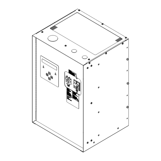
Micro ARE-M Series 24V Chargers, Single Phase Maintenance 12" CABINET ASSEMBLY AND SCHEMATICS Note: See Table 6-2 Parts Lists for reference designators and part numbers. FIGURE 6-2 12" Cabinet Assembly PM990-1070-24, Issue 12... -
Page 63: Figure 6-3 12" Cabinet Schematic; Are-M02406, 120/208/240
Micro ARE-M Series 24V Chargers, Single Phase Maintenance FIGURE 6-3 12" Cabinet Schematic; ARE-M02406, 120/208/240 PM990-1070-24, Issue 12... -
Page 64: Figure 6-4 12" Cabinet Schematic; Are-M02412, 120/208/240
Micro ARE-M Series 24V Chargers, Single Phase Maintenance FIGURE 6-4 12" Cabinet Schematic; ARE-M02412, 120/208/240 PM990-1070-24, Issue 12 6-10... -
Page 65: Figure 6-5 12" Cabinet Schematic, Are-M02425, 120/208/240
Micro ARE-M Series 24V Chargers, Single Phase Maintenance FIGURE 6-5 12" Cabinet Schematic, ARE-M02425, 120/208/240 PM990-1070-24, Issue 12 6-11... -
Page 66: 24" Cabinet Assembly And Schematics
Micro ARE-M Series 24V Chargers, Single Phase Maintenance 24" CABINET ASSEMBLY AND SCHEMATICS Note: See Table 6-2 Parts Lists for reference designators and part numbers. FIGURE 6-6 24" Cabinet Assembly PM990-1070-24, Issue 12 6-12... -
Page 67: Figure 6-7 24" Cabinet Schematic; Are-M02450, 120/208/240
Micro ARE-M Series 24V Chargers, Single Phase Maintenance FIGURE 6-7 24" Cabinet Schematic; ARE-M02450, 120/208/240 PM990-1070-24, Issue 12 6-13... -
Page 68: Figure 6-8 24" Cabinet Schematic; Are-M02450, 480
Micro ARE-M Series 24V Chargers, Single Phase Maintenance FIGURE 6-8 24" Cabinet Schematic; ARE-M02450, 480 PM990-1070-24, Issue 12 6-14... -
Page 69: Figure 6-9 24" Cabinet Schematic; Are-M024100, 120/208/240
Micro ARE-M Series 24V Chargers, Single Phase Maintenance FIGURE 6-9 24" Cabinet Schematic; ARE-M024100, 120/208/240 PM990-1070-24, Issue 12 6-15... -
Page 70: Figure 6-10 24" Cabinet Schematic; Are-M024100, 480
Micro ARE-M Series 24V Chargers, Single Phase Maintenance FIGURE 6-10 24" Cabinet Schematic; ARE-M024100, 480 PM990-1070-24, Issue 12 6-16... -
Page 71: Parts List
Micro ARE-M Series 24V Chargers, Single Phase Maintenance PARTS LIST This section contains the parts list for each standard charger model. TABLE 6-2 12" CABINET REPLACEMENT PARTS LIST; 24 VDC MODELS Model ARE-M02406 ARE-M02412 ARE-M02425 Voltage 120/208/240 120/208/240 120/208/240 Base Unit 102.1041.00A 102.1042.00A... - Page 72 Micro ARE-M Series 24V Chargers, Single Phase Maintenance 12” Cabinet Replacement Parts List; 24VDC Models, Continued… Model ARE-M02450 ARE-M02450 ARE-M024100 ARE-M024100 Voltage 120/208/240 120/208/240 Base Unit 102.1044.00A 102.1071.00A 102.1045.00A 102.1072.00A Designator Description 24" Cabinet 24" Cabinet 24" Cabinet 24" Cabinet A1 (Utility) Interface PCB 306.3078.24...
-
Page 73: Interface Board
Micro ARE-M Series 24V Chargers, Single Phase Maintenance INTERFACE BOARD This section provides Interface Board troubleshooting and replacement information. The Interface Board can be replaced in the field. There are no user-serviceable parts on the board. The board is shown in Figure 6-11. Use caution when servicing or replacing the board since battery voltage is present on the board whenever the battery string is connected to the charger. -
Page 74: Troubleshooting
Micro ARE-M Series 24V Chargers, Single Phase Maintenance 6.8.2 Troubleshooting 1. If the charger is not working properly, there are test points on the Interface Board that can help locate the problem. TP1 is board common and is used for all other test point voltage measurements. TP2, TP3, and TP4 are the DC-DC power supply outputs. -
Page 75: Figure 6-11 Component Locations, Interface Board
Micro ARE-M Series 24V Chargers, Single Phase Maintenance EXTERNAL TEMPERATURE PROBE CONNECTOR CHARGER CONNECTOR (4 PIN) (OPTIONAL) TEMPERATURE PROBE BLUE BLACK CHARGER CONNECTOR (3 PIN) SW1 & SW2 CHARGER CONNECTOR (17 PIN) CONTROL BOARD CONNECTOR (40 PIN) FIGURE 6-11 COMPONENT LOCATIONS, INTERFACE BOARD PM990-1070-24, Issue 12 6-21... -
Page 76: Control And Display Board
Micro ARE-M Series 24V Chargers, Single Phase Maintenance 6.9 CONTROL AND DISPLAY BOARD Figure 6-12 shows the Control and Display Board. There are no user-serviceable parts on the board. Board substitution is recommended when troubleshooting. 2-Line LCD Display On/Off Alarm LED FIGURE 6-12 CONTROL AND DISPLAY BOARD 6.9.1 Replacing the Board... -
Page 77: Keypad
Micro ARE-M Series 24V Chargers, Single Phase Maintenance 6.10 KEYPAD The front panel 4-button keypad can be replaced. Be sure a replacement part is on hand before beginning the following procedure. IMPORTANT: Carefully align the replacement keypad with the 2-line LCD display and LEDs before allowing the keypad to contact the front panel. -
Page 78: Options And Accessories
Micro ARE-M Series 24V Chargers, Single Phase Options and Accessories 7.0 OPTIONS AND ACCESSORIES This chapter contains details about the options and accessories currently available for the charger. Lightning Arrester A surge suppression device connected across the AC service to ground prevents high-energy transients from damaging the equipment. -
Page 79: Blocking Diode
Micro ARE Series 24V Chargers, Single Phase Options and Accessories Blocking Diode A silicon diode inserted into the negative DC output prevents the flow of reverse current from the battery when the equipment is DC-energized preventing additional battery drain. For systems with blocking diodes, the Float and Equalize voltage shoudl be set about 0.7 volts above the desired battery voltage to compensate for the diode voltage drop. -
Page 80: Output Movs
Ethernet network connection using the popular DNP3 protocol. More information about this protocol can be found at http://www.dnp.org. The DNP3 device profile (PM990.1072.00) and installation guide (PM990.1074.00) can be found on UNIPOWER’s web site at http://www.unipowerco.com. High interrupt AC breakers This option gives the charger an enhanced AC line current interrupting rating of at least 10,000 Amps.
Need help?
Do you have a question about the ARE-M02406 and is the answer not in the manual?
Questions and answers