Table of Contents
Troubleshooting

Related Manuals for Unipower ARE–S Series


Summary of Contents for Unipower ARE–S Series
- Page 1 Product Manual ARE–S Series 48V and 130V Float Chargers Single-Phase Input UNIPOWER, LLC 65 Industrial Park Rd Dunlap, TN 37327 Phone: +1-954-346-2442 Toll Free: 1-800-440-3504 PM990.1090.XX, Rev. 10 Web site – www.unipowerco.com...
-
Page 2: Important Safety Instructions
UNIPOWER, LLC presents all equipment to the delivering carrier securely packed and ready for transport. Upon acceptance of the equipment from us, the delivering carrier assumes responsibility for its safe delivery to you. Once you receive the equipment, it is your responsibility to document any damage to the equipment that was sustained during transport to you and to file your claim with the carrier promptly and accurately. - Page 3 UNIPOWER, LLC at the delivering carrier's expense. Be sure that the equipment is properly packaged for shipment. If repair is necessary, UNIPOWER, LLC will invoice you for the repair so that you may submit the bill to the delivering carrier with your claim form.
- Page 4 Use care in handling and unpacking the charger. Refer to the previous sections as needed. NAMEPLATE A UNIPOWER, LLC product is identified by a nameplate that includes model number, part number, and serial number information, as appropriate. Please include this information in all correspondence with UNIPOWER, LLC.
-
Page 6: Table Of Contents
ARE-S Series Chargers, Single Phase Contents Table of Contents 1. INTRODUCTION ................................1-1 PRODUCT DESCRIPTION........................... 1-1 MODEL DESIGNATION ............................1-2 1.2.1 Options ................................1-2 1.3.1 Mechanical ................................1-2 1.3.2 Electrical ................................1-5 1.3.3 Front Panel Displays and Controls ........................1-7 1.3.4 Environmental .............................. - Page 7 ARE-S Series 130V Chargers, Single Phase Contents 4.3.16 ARE-S user-programmable alarm relays functionality ..................4-18 4.3.17 User-programmable Alarm Relays Setup and Operation ................. 4-19 4.3.18 Factory Calibration ............................4-20 4.3.19 Field Calibrations ............................. 4-20 5. CIRCUIT DESCRIPTION ..............................5-1 6. MAINTENANCE ................................6-1 PREVENTIVE ...............................
- Page 8 ARE-S Series Chargers, Single Phase Contents List of Figures FIGURE 2-1 ELECTRICAL INSTALLATION, BLOCK DIAGRAM .................. 2-5 FIGURE 2-2 TYPICAL CHARGER ELECTRICAL ENTRANCE AND BREAKER LOCATIONS ........2-6 FIGURE 2-3 ELECTRICAL INSTALLATION TERMINALS, 12" CABINET MODELS ........... 2-7 FIGURE 2-4 ELECTRICAL INSTALLATION TERMINALS, 17”, 24”, AND 30" CABINET MODELS ......2-7 FIGURE 2-5 INTERFACE BOARD CONNECTIONS ......................
-
Page 9: Introduction
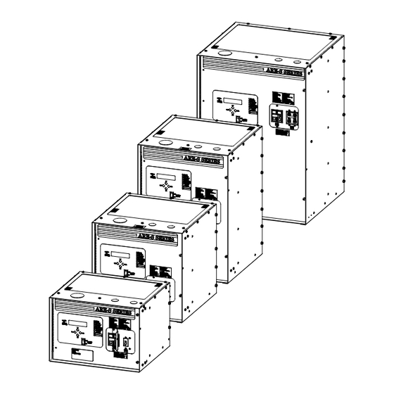
The purpose of this manual is to provide the reader with the procedures for installing, configuring, operating, and servicing UNIPOWER ARE-S Chargers. Both 48V and 130V models are covered by this manual. Chapter 1 Introduction provides a description of the ARE-S series chargers, the model designation list, and detailed specifications. -
Page 10: Model Designation
Drip Shield ........Prevents overhead drops from entering unit Engraved Nameplates ......Contact UNIPOWER Applications Engineering Fungicide Treatment ......Applied to inside of charger, contact UNIPOWER Applications Engineering SPECIFICATIONS This section provides the mechanical, electrical, and environmental specifications. The charger nameplate is located on the front panel. -
Page 11: Table 1-1 48V Model Designation
ARE-S Series Chargers, Single Phase Introduction TABLE 1-1 48V Model Designation DC VOLTAGE & CURRENT ARE-S4806A (AC Input Voltage: 120V/208V/240V) ARE-S4812A (AC Input Voltage: 120V/208V/240V) ARE-S4830A (AC Input Voltage: 120V/208V/240V) ARE-S4850A (AC Input Voltage: 120V/208V/240V) AC Input Voltage / Breaker 120V - 60 Hz Standard Capacity (10kAIC) AC Breaker 208V - 60 Hz Standard Capacity (10kAIC) AC Breaker 240V - 60 Hz Standard Capacity (10kAIC) AC Breaker... -
Page 12: Table 1-2 130V Model Designation
ARE-S Series Chargers, Single Phase Introduction TABLE 1-2 130V Model Designation DC VOLTAGE & CURRENT ARE-S13006A (AC Input Voltage: 120V/208V/240V) ARE-S13012A (AC Input Voltage: 120V/208V/240V/480V) ARE-S13016A (AC Input Voltage: 120V/208V/240V/480V) ARE-S13025A (AC Input Voltage: 120V/208V/240V/480V) ARE-S13035A (AC Input Voltage: 120V/208V/240V/480V) ARE-S13050A (AC Input Voltage: 208V/240V/480V) ARE-S13075A (AC Input Voltage: 240V/480V) AC Input Voltage / Breaker... -
Page 13: Electrical
ARE-S Series Chargers, Single Phase Introduction TABLE 1-3 Cabinet Dimensions by Model Cabinet Depth Mounting Shipping Model Height* Width* Size Maximum* Depth** Weight* ARE-S4806 104 (47) 12.25 ARE-S4812 12" 110 (50) (311) (432) (381) (152) ARE-S13006 103(47) ARE-S4830 168 (76) ARE-S13012 17.5 151 (69) - Page 14 ARE-S Series Chargers, Single Phase Introduction Current Limiting Factory Setting ......110% of full rated load Field Settable ......50-110% of full rated load Continuous Operation ....110% of full rated load maximum Surge Protection ........ Optional lightning arrestor on input terminals Optional MOVs (metal-oxide varistors) on output terminals Current Walk-In (Soft Start) .....
-
Page 15: Front Panel Displays And Controls
ARE-S Series Chargers, Single Phase Introduction TABLE 1-5 Model Specific and Related Specifications Refer to the equipment nameplate for the model number of the ARE-S at hand. Recommended Input Current, Output DC Circuit Model DC Cable Size, Terminal 120/208/240 Current Breaker Capacity ARE-S4806... -
Page 16: Environmental
ARE-S Series Chargers, Single Phase Introduction TABLE 1-6 Settable Parameters, Standard Models Model Float Range Equalize Range HVSD Range ARE-S130 Series 120.0-141.0V Float-147.0V 120-151.8V ARE-S48 Series 48.0V-56.4V Float-58.8V 54.0V-60.2V Alarm Adjustments (password protection available) Low Voltage (LVA) ......1.50-2.20 Vpc; alarm delay 1-300 seconds Very Low Voltage (VLVA) .... -
Page 17: Abbreviations And Acronyms
ARE-S Series Chargers, Single Phase Introduction ABBREVIATIONS AND ACRONYMS Listed here are many of the abbreviations and acronyms that may appear in this manual. Abbreviation, Acronym Or Symbol Meaning plus or positive minus or negative alternating current AC Fail ANSI American National Standards Institute american wire gauge BATT... -
Page 18: Product Support
Phone: +1-954-346-2442 Toll Free: 1-800-440-3504 Web site – www.unipowerco.com When contacting UNIPOWER, please be prepared to provide: 1. The product model number, spec number, S build number, and serial number - see the equipment nameplate on the front panel 2. Your company’s name and address 3. -
Page 19: Installation
Installation 2. INSTALLATION This chapter describes installing ARE-S Series Chargers. To contact a UNIPOWER field service technician for assistance, refer to Section 1.5 Product Support. The charger is fully assembled and tested at the factory. Refer to the Front Matter and Section 2.3 Unpacking for receiving and unpacking instructions and for instructions on moving the equipment to the installation site. -
Page 20: Reference Material
ARE-S Series Chargers, Single Phase Installation 10. Set LVA, HVA, HVSD, float voltage, equalization, etc. as needed to satisfy installation requirements. Test and verify charger setup and operation. See Chapter 4 Setup and Operation. REFERENCE MATERIAL This section contains lists, tables, and methods that are referenced in subsequent procedures. Three subsections comprise the Reference Material section. -
Page 21: Table 2-1 Copper Wire Sizing
ARE-S Series Chargers, Single Phase Installation Assume a maximum output current of 25 amperes, an allowable loop voltage drop of 0.5 volts, and a distance of 50 feet between the charger and the load. I = 25 amperes L = 50 feet V = 0.5 volts 11. -
Page 22: Mechanical Installation
ARE-S Series Chargers, Single Phase Installation 2.2.2.1.1 Torque Specifications Proper Charger performance requires that the hardware employed during installation be tightened securely, but not over tightened. Use a torque wrench to ensure that hardware is tightened to the specification provided in the table 2-2. -
Page 23: Electrical Installation
If there are sustained AC voltage fluctuations outside the ranges given in the Specifications section of this manual, contact the Field Service Department of UNIPOWER. A block diagram of a typical charger electrical installation is shown in Figure 2-4. Note that the load is connected to the battery string terminals through a fuse or circuit breaker. -
Page 24: Figure 2-2 Typical Charger Electrical Entrance And Breaker Locations
ARE-S Series Chargers, Single Phase Installation Chargers are furnished with three holes for top conduit entrances; see Figure 2-2. These holes can be enlarged to accommodate 1-1/2” conduit. FIGURE 2-2 TYPICAL CHARGER ELECTRICAL ENTRANCE AND BREAKER LOCATIONS All charger connection terminals are accessed by opening the hinged front door panel. AC input and DC output power terminals are located on the accessory panel at the right front of the unit. -
Page 25: Figure 2-3 Electrical Installation Terminals, 12" Cabinet Models
ARE-S Series Chargers, Single Phase Installation Terminal Block, TB1 DC(+) Output AC Input, Ground DC(-) Output AC Input, L1 AC Input, L2 or Neutral DC Circuit Breaker AC Circuit Breaker FIGURE 2-3 ELECTRICAL INSTALLATION TERMINALS, 12" CABINET MODELS *GENERIC; MAY VARY PER SYSTEM AC Input L2 DC (+) Output or neutral... -
Page 26: Grounding The Cabinet
A tag in the unit tells the factory voltage setting. If the AC input voltage must be changed, contact UNIPOWER Field service for voltage changeover instructions. Refer to the PN and SD drawings to locate the cabinet assembly and schematic for the model at hand. Each schematic has a table and a connector detail drawing showing the needed connections. -
Page 27: Connecting The Battery String
ARE-S Series Chargers, Single Phase Installation 2.4.4 Connecting the Battery String Routing stiff, heavy gauge battery cables can be difficult. Two people may be needed. Exercise extreme caution to avoid a short circuit across the battery terminals. WARNING AVERTISSEMENT Arcing hazard Risque d'arc Arcing can cause equipment damage, load Un arc électrique peut causer des dommages sur les... -
Page 28: Connecting Alarm Annunciation
ARE-S Series Chargers, Single Phase Installation 13. Carefully check cable polarity and connect the cables. 2.4.6 Connecting Alarm Annunciation Connect user-supplied alarm annunciators to terminal blocks J14 thru J16 on the Interface Board and J1 thru J10 on the optional Extended Alarm Relay board, if applicable. Refer to Section 1.3 Specifications for alarm relay specifications and for recommended wire size. -
Page 29: Figure 2-5 Interface Board Connections
ARE-S Series Chargers, Single Phase Installation Customer Alarm Wiring Removable Plug TB1, Interface Board-Mounted Terminal Blocks FIGURE 2-5 INTERFACE BOARD CONNECTIONS Customer Alarm Wiring Removable Plug TB1, Interface Board-Mounted Terminal Blocks FIGURE 2-6 RELAY BOARD ALARM CONNECTIONS PM990.1090.XX, Rev. 10 2-11... -
Page 30: Connecting The Battery Temperature Probe (Option)
ARE-S Series Chargers, Single Phase Installation 2.4.7 Connecting the Battery Temperature Probe (Option) When the battery temperature probe option is ordered with the charger, a temperature probe is connected to the charger’s Interface Board and the probe and wires coiled and tied near the Interface Board, behind the front panel. To connect the battery temperature probe: 1. -
Page 31: Commissioning
ARE-S Series Chargers, Single Phase Commissioning 3. COMMISSIONING This chapter describes configuring, commissioning, and operating an ARE-S Series unit. A front view of a typical charger is shown in Figure 3-1. All operator controls are on the front of the charger. 2-Line Display 4-Button... -
Page 32: Commissioning Procedure
ARE-S Series Chargers, Single Phase Commissioning Battery String Connected to Charger – The string will power the charger controller if there is at least a • minimal battery charge. The 2-line display, keypad, and Alarm LEDs will be active. The setup can be edited at the charger front panel without applying AC power to the charger. - Page 33 ARE-S Series Chargers, Single Phase Commissioning 7. Connect a load of about 10% of charger capacity to the battery terminals through a circuit breaker or fuse. If a battery string is not connected, wire the load directly to the charger DC output terminals. Refer to the Section 2 Installation as necessary.
-
Page 34: Setup And Operation
ARE-S Series Chargers, Single Phase Setup and Operation 4. SETUP AND OPERATION This chapter describes setting up and operating an ARE-S Series Charger using the 2-line display and 4-button keypad on the charger. See Figure 3-1 for the location of the panel, display, and keypad. The figure also shows the locations of the AC and DC circuit breakers mentioned in sections 4.1 &... -
Page 35: The Home Screen And Menus
ARE-S Series Chargers, Single Phase Setup and Operation When changing a parameter value using UP or DN, a single press will increment (UP) or • decrement (DN) the value. Pressing and holding either button will cause the value to scroll, allowing large value changes to be made quickly. -
Page 36: Figure 4-2 Charger Status Menu
ARE-S Series Chargers, Single Phase Setup and Operation The Active Alarms screen will show all current alarms. If multiple alarms are present, their alarm descriptors will scroll through the screen. Press SEL at the Charger Status screen to view charger operating parameters; see Figure 4-2. Parameter values cannot be changed in this series of screens. -
Page 37: Figure 4-4 Charger Setup (Configuration) Menu
ARE-S Series Chargers, Single Phase Setup and Operation Main Menu Select Status Screens Parameter Screens Charger Setup System Setpoints Change Float Voltage From Figure 4-1 Change EQ Voltage Change LVA Voltage Note: Change HVA Voltage Paramether values are Change HVSD Voltage read-only in this series Change NCA Current of menus. -
Page 38: View Active Alarms
ARE-S Series Chargers, Single Phase Setup and Operation 4.3.3 View Active Alarms All active alarms appear in the Active Alarms screen. Multiple alarms will scroll across the screen. A “red” STATUS LED indicates alarms are present. A “green” STATUS LED indicates no alarms are present. -
Page 39: Alarm Relay/Lamp Test
ARE-S Series Chargers, Single Phase Setup and Operation 4. At the Enter Password screen, press UP until your password is displayed and then press SEL. Go to step 5. 5. At the Begin Equalize screen, press one of the following: Press SEL to select equalize mode. -
Page 40: System Setpoints, System Alarms, And Summary Alarm
ARE-S Series Chargers, Single Phase Setup and Operation TABLE 4-1 Factory Default Setup Parameter Values Parameter 48 Vdc Models 130 Vdc Models Operating Mode (FL/EQ) Float Float Float Setpoint 52.8V 132.0V Equalization (EQ) 56.0V 140.0V Low Voltage Alarm (LVA) 48.0V 125.0V Very Low Voltage Alarm (VLVA) 46.6V... -
Page 41: High Voltage Alarm (Hva)
ARE-S Series Chargers, Single Phase Setup and Operation 4.3.9.3 High Voltage Alarm (HVA) Set the HVA alarm to a voltage that, if charger output voltage goes above this setting, an alarm will be annunciated. 4.3.9.4 Primary (software) High Voltage Shutdown Voltage (HVSD) Set the HVSD alarm to a voltage that, if charger output voltage goes above this setting the charger will shutdown. -
Page 42: Rectifier Fail Alarm (Rectf)
ARE-S Series Chargers, Single Phase Setup and Operation ** Additional equalize charging is not recommended after initial charge equalization. Consult battery manufacturer for particular recommendations. Note: Lead-calcium alloy grid batteries do not require regular equalizing. Set the equalization voltage to equal the float voltage. 4.3.9.8 Rectifier Fail Alarm (RECTF) Rectifier fail indicates the inability of the charger to maintain the desired float setpoint. -
Page 43: Auto-Equalize
ARE-S Series Chargers, Single Phase Setup and Operation 9. Press UP or DN to display the desired mv/Cell/C value. Press SEL to store the new value. 10. Press ESC to return to the Temperature Compensation Coeff. screen. Press DN to go to the number of cells screen. -
Page 44: Load Share
ARE-S Series Chargers, Single Phase Setup and Operation To enable Periodic Equalize, Press SEL. The equals sign will flash. Press UP to display enable • Periodic Equalize and display the Periodic Equalize Periodic Equalize every screen. Go to Step 9. = DISABLED •... -
Page 45: Figure 4-5 Issue 1 Control Board (Not Load Share Compatible)
ARE-S Series Chargers, Single Phase Setup and Operation board without the isolator board. Doing so may cause undesired charger operation or cause failure of the charger and components. The load share repeater board is not required for issue 2 control boards and later. See the following figures for an easy visual check on the control board version. -
Page 46: Figure 4-8 2-Charger Load Share Setup Example
ARE-S Series Chargers, Single Phase Setup and Operation Isolator/Repeater Board Cat5e Cat5e 306.2988.00 (Use with ISS 1A boards only) J3-Next J4-Prev Charger Charger Master Charger Sub Charger Load share Load share Settings: Settings: EOL = Y EOL = Y Address = 1 Address = 2 # of Chgrs = 2 # of Chgrs = 2... -
Page 47: Figure 4-10 Eol (End Of Line) Jumper (Issue 2A Board Shown)
ARE-S Series Chargers, Single Phase Setup and Operation FIGURE 4-10 EOL (END OF LINE) JUMPER (ISSUE 2A BOARD SHOWN) Note: EOL jumper location may vary on other board issues. LOAD SHARE LOAD SHARE LOAD SHARE # of Chgrs = 3 Charger Addr. -
Page 48: Activating Load Share
ARE-S Series Chargers, Single Phase Setup and Operation FIGURE 4-11 LOAD SHARE CONFIGURATION MENU SCREENS To enable Load Share from the front panel: 1. From the Home screen, press UP or DN until CHARGER SETUP appears. Press SEL. 2. From the Load Share screen press SEL. The Load Share Disabled screen will appear. 3. -
Page 49: Password
Any number between 00002 and 65500 can be used as the password. Select a password that is easy to remember but difficult for others to guess. As with any password, secrecy is required for meaningful security. If the password is forgotten, contact UNIPOWER Field Service. PM990.1090.XX, Rev. 10... -
Page 50: Factory Defaults
ARE-S Series Chargers, Single Phase Setup and Operation A. Enabling and Setting a Password: At the Home screen, press UP or DN until the CHARGER SETUP appears. Press SEL. Enter Old Password None (disabled) At the System Setpoints screen, press UP or DN until the Password screen appears. -
Page 51: Are-S User-Programmable Alarm Relays Functionality
ARE-S Series Chargers, Single Phase Setup and Operation TABLE 4-3 Default (Standard) Charger Settings Cells Nominal Float Equalize HVSD VLVA GND Fault HBTA Voltage 52.8 56.0 48.0 46.6 58.0 See Table 1000 ohms 132.0 140.0 120.0 116.4 See Table 1000 ohms Charger Rating Default NCA Setting 0.12 A... -
Page 52: User-Programmable Alarm Relays Setup And Operation
ARE-S Series Chargers, Single Phase Setup and Operation FIGURE 4-14 FRONT PANEL CUSTOM LEDS 4.3.17 User-programmable Alarm Relays Setup and Operation The alarm relays are configured under the CHARGER SETUP menu; the setup of both alarms is identical. Each relay can be assigned a single alarm to be actuated from or a logical OR or logical AND combination of the available alarm conditions. -
Page 53: Factory Calibration
LED. FIGURE 4-15 DIGITAL INPUTS 4.3.18 Factory Calibration Factory Calibration is intended for use by factory personnel and is not field accessible. Contact UNIPOWER Field Service for additional information. 4.3.19 Field Calibrations No calibration settings are field adjustable. All other field adjustments are described previously in this chapter. -
Page 54: Circuit Description
ARE-S Series Chargers, Single Phase Circuit Description 5. CIRCUIT DESCRIPTION Figure 5-1 is a functional block diagram of a ARE-S series float charger. AC input power is applied through the input circuit breaker to the power transformer. The circuit breaker provides over-current and fault protection in case of malfunction or a short circuit in the input side of the equipment. - Page 55 ARE-S Series Chargers, Single Phase Circuit Description The front panel consists of a 2-line digital display, a 4-button keypad, and LEDs. The display and LEDs are mounted directly to the Control and Display Board. Alarm connections for external annunciation of alarms are provided on the Interface Board and an optional Extended Alarm Relay Board.
-
Page 56: Maintenance
ARE-S Series Chargers, Single Phase Maintenance 6. MAINTENANCE This chapter provides preventive maintenance procedures and troubleshooting procedures. Cabinet assembly drawings, schematics, and parts lists for all standard charger models are included in this chapter. Refer to the replacement parts lists in the PN drawing that accompanies you charger when ordering on-hand spare parts and service replacement parts. -
Page 57: Troubleshooting
ARE-S Series Chargers, Single Phase Maintenance TROUBLESHOOTING Table 6-1 is a troubleshooting chart designed to help a qualified technician diagnose the cause of a charger malfunction. While troubleshooting, refer to the cabinet assembly drawing and the schematic diagram for the charger model at hand. -
Page 58: Are-S Lcd Display Codes
ARE-S Series Chargers, Single Phase Maintenance 6.2.3 ARE-S LCD Display Codes The charger operating state will toggle on the 2 line of the LCD display with the active alarms. The active alarms will continue to toggle until any key on the front panel is pressed acknowledging that the alarms have been viewed by a user. Once acknowledged the display will only show the present operating state. - Page 59 ARE-S Series Chargers, Single Phase Maintenance Charger Alarm Codes Description AC Fail – The charger does not detect incoming AC voltage. The utility supply to the charger is unavailable (power outage), the breaker at the customer service panel is off/tripped, the charger’s AC breaker is off/tripped, or an interface board failure has occurred.
-
Page 60: Table 6-1 Troubleshooting Chart
ARE-S Series Chargers, Single Phase Maintenance TABLE 6-1 Troubleshooting Chart Symptom Possible Cause(s) Solution(s) A. AC breaker trips 1. Short circuit in AC power circuit Inspect primary wiring for possible shorts or grounded connections. 2. Input connected for lower voltage. a. - Page 61 ARE-S Series Chargers, Single Phase Maintenance E. DC breaker trips. 1. Battery connection reversed. Check polarity of battery connections. 2. Short circuit in DC power circuit. a. Inspect secondary power wiring and terminals for shorts or grounded connections. b. Check power of SCR (and DC filter capacitors). 4.
- Page 62 ARE-S Series Chargers, Single Phase Maintenance 3. Communications with Master a. Check for bad communications cable charger lost b. Faulty control board. Replace board. c. End of Line (EOL) jumpers not set properly. Refer to load share section of manual. 4.
-
Page 63: Checking Components
CHECKING COMPONENTS This section describes methods that can be employed to determine whether a component has failed. A failed component must be replaced with a UNIPOWER approved part. See PN drawing(s) for parts list for component descriptions and UNIPOWER part numbers. -
Page 64: Interface Board (306.2991.48 Or 306.2991.130)
ARE-S Series Chargers, Single Phase Maintenance INTERFACE BOARD (306.2991.48 OR 306.2991.130) This section provides Interface Board troubleshooting and replacement information. The Interface Board can be replaced in the field. There are no user-serviceable parts on the board. The board is shown in Figure 6-1. Use caution when servicing or replacing the board since battery voltage is present on the board whenever the battery string is connected to the charger or when the charger has AC applied. -
Page 65: Replacing The Interface Board
ARE-S Series Chargers, Single Phase Maintenance TP16 to TP8 should be about the same as TP16 to TP7 (assuming the DC breaker is closed). TP16 to TP9 should be about 0.6V for a 48V charger and 1.28V on a 130V charger if there is no ground short. -
Page 66: Control And Display Board (306.2993.00)
ARE-S Series Chargers, Single Phase Maintenance CONTROL AND DISPLAY BOARD (306.2993.00) Figure 6-2 shows the Control and Display Board. There are no user-serviceable parts on the board. Board substitution is recommended when troubleshooting. Contact field service for control board and interface board firmware compatibility. -
Page 67: Control Power Supply Board (306.2990.48 Or 306.2990.130)
ARE-S Series Chargers, Single Phase Maintenance CONTROL POWER SUPPLY BOARD (306.2990.48 OR 306.2990.130) Figure 6-3 shows the Control Power Supply Board. There are no user-serviceable parts on the board. Board substitution is recommended when troubleshooting. The charger must be turned off when replacing this board. The power supply board is voltage specific. -
Page 68: Scr Trigger Board (306.2989.00)
ARE-S Series Chargers, Single Phase Maintenance SCR TRIGGER BOARD (306.2989.00) Figure 6-4 shows the SCR Trigger Board. There are no user-serviceable parts on the board. Board substitution is recommended when troubleshooting. The charger must be turned off when replacing this board. FIGURE 6-4 SCR TRIGGER BOARD 6.7.1 Replacing the Board... -
Page 69: Extended Relay Board (306.2994.00)
ARE-S Series Chargers, Single Phase Maintenance EXTENDED RELAY BOARD (306.2994.00) Figure 6-5 shows the Extended Relay board. There are no user-serviceable parts on the board. Board substitution is recommended when troubleshooting. Note: Alarms may occur when replacing this board. FIGURE 6-5 EXTENDED RELAY BOARD 6.8.1 Replacing the Board The charger does not have to be turned off to replace the Extended Relay board. -
Page 70: Options And Accessories
ARE-S Series Chargers, Single Phase Options and Accessories 7. OPTIONS AND ACCESSORIES This chapter contains details about the options and accessories currently available for the charger. LIGHTNING ARRESTER A surge suppression device connected across the AC service to ground prevents high energy transients from damaging the equipment. -
Page 71: Blocking Diode
ARE-S Series Chargers, Single Phase Options and Accessories BLOCKING DIODE A silicon diode inserted into the negative DC output prevents the flow of reverse current from the battery when the equipment is DC-energized preventing additional battery drain. Note: Current drain without the blocking diode is typically less than 100 mA 6A, 12A, and 16A rated Systems 25A through 50A rated Systems 75A rated System... -
Page 72: Output Movs
ARE-S Series Chargers, Single Phase Options and Accessories OUTPUT MOVS The output MOVs protect the charger from externally created voltage transients. The MOVs are connected from each output pole of the charger to the cabinet (earth). If an excessive transient enters the unit on the output cables, the MOVs clamp the voltage to an acceptable level.
Need help?
Do you have a question about the ARE–S Series and is the answer not in the manual?
Questions and answers