Table of Contents
Advertisement
Advertisement
Chapters
Table of Contents

Related Manuals for Unipower ARR-M Series


Summary of Contents for Unipower ARR-M Series
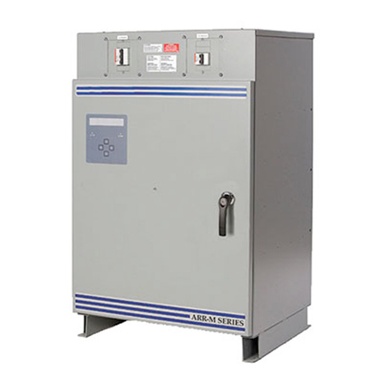
- Page 1 ARR-M Series Product Manual UNIPOWER, LLC 65 Industrial Park Rd PM990.7800.00, Rev. 4 Dunlap, TN 37327 Phone: +1-954-346-2442 Revision History Checked/Approved Toll Free: 1-800-440-3504 PCO# & Date Web site – www.unipowerco.com 45404 W.Deakins 7/10/19...
- Page 2 BATTERY CHARGER USER’S MANUAL ~ i ~...
-
Page 3: Table Of Contents
Table of content PART – 1 : INSTALLATION .............................. 1 INTRODUCTION................................ 2 IMPORTANT SAFETY INSTRUCTIONS .......................... 2 STORAGE / MAINTENANCE DURING STORAGE ...................... 2 PLACEMENT AND INSTALLATION .......................... 2 VENTILATION AND COOLING ............................ 3 ELECTRICAL CONNECTIONS AND WIRING ........................ 4 POWERING UP ................................ 4 SYSTEM POWERING OFF PROCEDURE .......................... 4 PART – 2: THEORY OF OPERATION ............................ 5 ... - Page 4 iii. Low Voltage Equalize (optional) .............................. 2 9 Low Capacity Equalize (optional) .............................. 3 0 Charger Equalize Start (optional) .............................. 3 1 AC Fail Equalize (optional) ................................ 3 2 vii. Refresh Equalize (optional) ................................ 3 3 viii. Remote Equalize (optional) ................................. 3 4 Current Limit Equalize (optional) .............................. 3 5 ...
- Page 5 FIGURE LIST .................................. 86 ACRONYM LIST .................................. 88 LCD MESSAGES LIST ................................ 90 APPENDIXES .................................. 92 ~ iv ~...
-
Page 6: Part - 1 : Installation
PART – 1 : INSTALLATION INSTALLATION MCEnPC23-REV.2.4 Page 1... -
Page 7: Introduction
BATTERY CHARGER USER’S MANUAL PART-1:INSTALLATION 1. INTRODUCTION This user manual contains important technical instructions to be followed by qualified personnel responsible for the installation, start-up, maintenance operations and knowledgeable on batteries and safety requirements/precautions involved. We recommend this manual to be read attentively to ensure safe and reliable operation of this equipment. Should you require any assistance, please call our service department. -
Page 8: Ventilation And Cooling
BATTERY CHARGER USER’S MANUAL PART-1:INSTALLATION Warning Battery application and maintenance: Your battery is a crucial back up for your critical application. Special care and appropriate safety and maintenance procedures must be implemented. Please refer to the battery manufacturer instructions and the applicable battery installation, maintenance, testing and replacement standards for stationary application in order to optimize the life of the battery as well as to determine when the battery should be replaced. -
Page 9: Electrical Connections And Wiring
BATTERY CHARGER USER’S MANUAL PART-1:INSTALLATION 6. ELECTRICAL CONNECTIONS AND WIRING Before connecting the battery charger ensure that: The battery is disconnected (if applicable) The circuit breakers are OFF The relays, fuses and circuit boards are installed The unit is wired in accordance with the instructions (refer to the wiring connections and electrical diagram) The appropriate cable sizes are very important. -
Page 10: Part - 2: Theory Of Operation
PART – 2: THEORY OF OPERATION THEORY OF OPERATION MCEnPC23-REV.2.4 Page 5... -
Page 11: Theory Of Operation
BATTERY CHARGER USER’S MANUAL PART- 2: THEORY OF OPERATION 1. THEORY OF OPERATION The battery charger provides a fully regulated and Isolated DC output from the main AC input. The LCD show continuously the battery charger status: DC Voltage, DC current, alarms …. LCD DISPLAY AND KEYPAD 10.5A 136.2V... -
Page 12: Accessing Menu Via Keypad
BATTERY CHARGER USER’S MANUAL PART- 2: THEORY OF OPERATION 2. ACCESSING MENU VIA KEYPAD All gray buttons in all figures inside this manual mean that this button is pressed and activated. When more than one button is gray, this means that we have a choice to press any button on keypad. WARNING! All values indicated in the following figures are given as examples. -
Page 13: Charging Modes
BATTERY CHARGER USER’S MANUAL PART- 2: THEORY OF OPERATION 3. CHARGING MODES “AC OUT” MODE In the case of a power outage, if the AC breaker is open or if the control board fuse has blown, an AC fail alarm will be generated, warning you that one of the cases has occurred. In this mode, the rectifier waits for the AC input to be reconnected to the charger or the control board. -
Page 14: Equalize Current Limit 2" Mode
BATTERY CHARGER USER’S MANUAL PART- 2: THEORY OF OPERATION Via a preset delay (periodically); Via external signal (optional); Via ModBus RS232 / RS485, or ModBus TCP/IP communication (optional); Via DNP3 RS232 / RS485 communication (optional); If DC Output voltage is within a preset value (Low Volt Equalize: optional); ... -
Page 15: Ac Input Voltage(S) And Current(S) (Optional)
BATTERY CHARGER USER’S MANUAL PART- 2: THEORY OF OPERATION 120.5V 10.2A Equalize Flt MODE Next Exit Float Exit Float Exit Float Equalize Float Exit Figure 9 : Enabling Manually Float or Equalize Mode. 5. AC INPUT VOLTAGE(S) AND CURRENT(S) (OPTIONAL) If this option is ordered, the AC Input Voltage and Current are displayed on the LCD. -
Page 16: Battery Current (Optional)
BATTERY CHARGER USER’S MANUAL PART- 2: THEORY OF OPERATION 6. BATTERY CURRENT (OPTIONAL) The current flowing IN or OUT of the battery will be displayed on LCD if this option is enabled. Negative (-) sign will be displayed in case of battery discharging. 20.1A 136.2V IBatt... -
Page 17: The Menu
BATTERY CHARGER USER’S MANUAL PART- 2: THEORY OF OPERATION Battery Test (optional). Formation test (optional). Language selection. DNP3 and Modbus Communication (optional). Battery charger parameter adjustment and visualization. Pre-programmable 4 messages, to be displayed on LCD (Refer to ModBus manual). ... -
Page 18: Events Format And Reset Procedure
BATTERY CHARGER USER’S MANUAL PART- 2: THEORY OF OPERATION 136.4V 50.1A Charger Output Home Screen Equalize Reset Alarms? This message will appear only if an alarm is active Pr Exit Next Press Next Mode This menu will display only if Next Pr Exit Equalize mode is Enabled... - Page 19 BATTERY CHARGER USER’S MANUAL PART- 2: THEORY OF OPERATION Associated Number Events Float mode Equalize mode Current limit mode Formation reserved Battery continuity test running Battery test OK Battery test fault Test problem Battery is under test Battery high voltage Battery low voltage High voltage shutdown Low voltage disconnect...
- Page 20 BATTERY CHARGER USER’S MANUAL PART- 2: THEORY OF OPERATION The following figure shows the procedure to visualize Events: Level0 Readings? Next Exit Events Next Exit E03/0804/0 10135 Next Exit Press F2 (or B) to visualize next event Press F3 (or C) to visualize previous event E08/0807/0 20138 Next...
- Page 21 BATTERY CHARGER USER’S MANUAL PART- 2: THEORY OF OPERATION Event Format: Event format is described as follow: Month Hour Year Minute E07/ Next Exit tenth Event Figure 14 : Event Format description. Reset Events : The following figure shows the procedure to Reset Events: Level0 Readings? Next...
- Page 22 BATTERY CHARGER USER’S MANUAL PART- 2: THEORY OF OPERATION 7.2.2 Readings By default, the readings are the battery DC voltage and the rectifier output current. The LCD can also show the following additional readings: Line Frequency. Rectifier output voltage. ...
-
Page 23: Relay Test
BATTERY CHARGER USER’S MANUAL PART- 2: THEORY OF OPERATION Acronyms : Refer to acronym list used for the battery charger at the end of this manual. 7.2.3 Relay test During relay test, all relays will be energized (or de-energized if you select the fail safe operation option) for 5 seconds;... -
Page 24: Lcd Power Save
BATTERY CHARGER USER’S MANUAL PART- 2: THEORY OF OPERATION 7.2.5 LCD Power Save If the LCD power save function is selected, the LCD back lighting will turn off after 5 min of inactivity. It will turn back on whenever a button is pressed or any alarm occurs. Level0 Readings? Next... -
Page 25: Run / Stop Battery Capacity Test (Optional)
BATTERY CHARGER USER’S MANUAL PART- 2: THEORY OF OPERATION 7.2.7 Run / Stop Battery Capacity Test (optional) The image below shows how to run or stop manually the battery-capacity-test. Level0 Readings? Next Exit Press Next till Battery Test? Next Exit Battery Test? Stop... -
Page 26: Run / Stop Formation Mode (Optional)
BATTERY CHARGER USER’S MANUAL PART- 2: THEORY OF OPERATION Level0 Readings? Next Exit Press Next till Synchro Next Exit sure? Synchro Figure 22 : Procedure to synchronize Ampere-Hour meter. 7.2.9 Run / Stop Formation Mode (optional) The formation mode is to be exclusively used to prime a battery as per its manufacturer instructions. In this mode, the charger forms the battery at the preset voltage and during the preset time, after which the charger will go back into the float mode. - Page 27 BATTERY CHARGER USER’S MANUAL PART- 2: THEORY OF OPERATION Level0 Readings? Exit Next Press Next till Formation Next Exit Formation Stop Formation Start Formation Stop Available! Figure 23 : Procedure to Run or Stop Formation Mode. Once Formation mode started, the LCD will show one of messages below, depending on Battery formation status 140.2V 137.6V 3.0A...
-
Page 28: Language
BATTERY CHARGER USER’S MANUAL PART- 2: THEORY OF OPERATION 7.2.10 Language Available languages with battery charger are English and French. The following figure shows the procedure to switch between the two languages: Level0 Readings? Next Exit Press Next till Fr Lang. - Page 29 BATTERY CHARGER USER’S MANUAL PART- 2: THEORY OF OPERATION 136.2V 50.0A Reset Alarms? Mode Level0 Readings? Level1 Adjust? Enter Password Exit Figure 26 : Procedure to access Level - 1. If a parameter is modified, the LCD will display the following screen to confirm changes. If the modification is not saved or canceled, the battery charger will keep the old value.
-
Page 30: Control
BATTERY CHARGER USER’S MANUAL PART- 2: THEORY OF OPERATION 7.3.1 Control a. Setting Voltage and Current for Float Mode The Float Voltage and Current are adjusted as follows: Level1 Adjust? Control? Float 136.2V Float 136.2V Exit Next ILim1 100.0A Next Exit Figure 28 : Procedure to adjust Float Voltage and Float Current. MCEnPC23-REV.2.4 Page 25... -
Page 31: Setting Voltage And Current For Equalize Mode
BATTERY CHARGER USER’S MANUAL PART- 2: THEORY OF OPERATION b. Setting voltage and current for Equalize Mode Level1 Adjust? Exit Next Control? Exit Next Press Next till 138.2V Next Exit 138.2V Exit Next Exit Next ILim2 100.0A Exit Next Figure 29 : Procedure to adjust Equalize Voltage and Equalize Current. MCEnPC23-REV.2.4 Page 26... -
Page 32: Equalization Start Parameter Adjustments (Optional)
BATTERY CHARGER USER’S MANUAL PART- 2: THEORY OF OPERATION Equalization Start parameter Adjustments (optional) In this sub menu, we can enable, disable and adjust different mode of starting Equalize. Manual Equalize (optional) If ordered, the charger can be configured for the manual “Equalize” mode. Please refer to your order and the battery manufacturer to confirm the equalize requirement. -
Page 33: Periodical Equalize (Optional)
BATTERY CHARGER USER’S MANUAL PART- 2: THEORY OF OPERATION Periodical Equalize (optional) If Periodical Equalize is enabled then the charger will go into “Equalize” mode every preset period. The period is adjustable between 1 day and 8191 days. The duration is adjustable between 1 and 8191 hours. We can enable or disable and adjust periodical Equalize as follows: Level1 Adjust? -
Page 34: Low Voltage Equalize (Optional)
BATTERY CHARGER USER’S MANUAL PART- 2: THEORY OF OPERATION iii. Low Voltage Equalize (optional) If the Low Voltage Equalize is enabled, then the charger will go into “Equalize” mode whenever the DC output voltage drops under a preset voltage. The duration is adjustable between 1 and 8191 hours. We can enable or disable and adjust low volt Equalize as follows: Level1 Adjust? -
Page 35: Low Capacity Equalize (Optional)
BATTERY CHARGER USER’S MANUAL PART- 2: THEORY OF OPERATION Low Capacity Equalize (optional) If the Low Capacity Equalize is enabled, then the charger will go into “Equalize” mode whenever the capacity battery decreases under a preset capacity. The duration is adjustable between 1 and 8191 hours. We can enable or disable and adjust low capacity Equalize as follows: Level1 Adjust? -
Page 36: Charger Equalize Start (Optional)
BATTERY CHARGER USER’S MANUAL PART- 2: THEORY OF OPERATION Charger Equalize Start (optional) If the charger Equalize Start is enabled, then the charger will go into “Equalize” mode when it starts (first time power up). The duration is adjustable between 1 and 8191 hours. We can enable or disable and adjust charger Equalize Start as follows: Level1 Adjust? -
Page 37: Ac Fail Equalize (Optional)
BATTERY CHARGER USER’S MANUAL PART- 2: THEORY OF OPERATION AC Fail Equalize (optional) If enabled, then the charger will go into “Equalize” mode after an AC mains failure. Equalize cycle will be during a period of time between 1 and 8191 hours. We can enable or disable and adjust AC fail Equalize as follows: Level1 Adjust? Exit... -
Page 38: Refresh Equalize (Optional)
BATTERY CHARGER USER’S MANUAL PART- 2: THEORY OF OPERATION vii. Refresh Equalize (optional) If Refresh Equalize is enabled, then the charger will go into “Equalize” mode for a preset time between 1 and 8191minutes every period between 1 and 8191 hours. Example: The charger will equalize the battery during 5min every 24 hours. -
Page 39: Remote Equalize (Optional)
BATTERY CHARGER USER’S MANUAL PART- 2: THEORY OF OPERATION viii. Remote Equalize (optional) If Remote Equalize is enabled, the charger will go into “Equalize” mode during a preset time between 1 and 8191 hours, if command is initiated by users via web page, or whenever an external normally open contact closes momentarily or permanently. -
Page 40: Current Limit Equalize (Optional)
BATTERY CHARGER USER’S MANUAL PART- 2: THEORY OF OPERATION Current Limit Equalize (optional) If Current Limit Equalize is enabled, the charger will go into “Equalize” mode during a preset time between 1 and 8191 hours, whenever the rectifier goes into the current limit for a period of time between 1 and 8191 seconds. We can enable or disable current limit Equalize as shown on the procedure below: Level1 Adjust? -
Page 41: Equalize Termination (Optional)
BATTERY CHARGER USER’S MANUAL PART- 2: THEORY OF OPERATION d. Equalize Termination (optional) We can stop Equalize mode manually as described on Part-2 / Paragraph-4. However, Equalize mode can be stopped also automatically as described on the following paragraph. Stopping Equalize after a preset delay: Security Time To ensure a security while the battery charger is operating in Equalize mode and in order to protect batteries, a preprogrammed time security can be set. -
Page 42: Voltage Post-Charge Mode (Optional)
BATTERY CHARGER USER’S MANUAL PART- 2: THEORY OF OPERATION Voltage Post-Charge Mode (optional) When the Voltage Post-Charge mode is selected, the charger will revert back from Equalize into the Float mode when the load voltage reaches the Equalize one during a preset time between 1 and 8191 minutes. We can enable or disable Voltage Post-Charge as shown on the procedure below: Level1 Adjust? -
Page 43: Current Post-Charge Mode (Optional)
BATTERY CHARGER USER’S MANUAL PART- 2: THEORY OF OPERATION iii. Current Post-Charge Mode (optional) If this option is enabled, the battery charger will revert back from Equalize to Float mode when Load current reaches a preset value between 5% and 95% of Equalize current limit value, during a preset time between 1 and 8191 minutes. -
Page 44: Temperature Post-Charge Mode (Optional)
BATTERY CHARGER USER’S MANUAL PART- 2: THEORY OF OPERATION Temperature Post-Charge Mode (optional) When the Temperature Post-Charge is selected, the charger will revert back from Equalize into the Float mode when the battery temperature reaches its preset value, during a preset time between 1 and 8191 minutes. We can enable or disable Temperature Post-Charge as shown on the procedure below: Level1 Adjust? -
Page 45: Capacity Post-Charge Mode (Optional)
BATTERY CHARGER USER’S MANUAL PART- 2: THEORY OF OPERATION Capacity Post-Charge Mode (optional) When the Capacity Post-Charge is selected, the charger will revert back from Equalize into the Float mode when the battery Capacity reaches its preset value, during a preset time between 1 and 8191 minutes. We can enable or disable Capacity Post-Charge as shown on the procedure below: Level1 Adjust? -
Page 46: Formation Mode Parameter Adjustments (Optional)
BATTERY CHARGER USER’S MANUAL PART- 2: THEORY OF OPERATION Formation Mode parameter adjustments (optional) We can enable or disable and adjust Formation Mode parameters as follows: Level1 Adjust? Exit Next Control? Exit Next Press Next till VForm 140.3V Next Exit VForm 140.3V Next Exit VForm Exit... -
Page 47: Load Sharing (Optional)
BATTERY CHARGER USER’S MANUAL PART- 2: THEORY OF OPERATION Load Sharing (optional) Two or more chargers may be used in parallel to share the same load and recharge the same battery. This parallel configuration is meant to improve site reliability and ease the routine service during shutdowns and preventive maintenance. - Page 48 BATTERY CHARGER USER’S MANUAL PART- 2: THEORY OF OPERATION Level1 Adjust? Exit Next Control? Exit Next Press Next till Load Sharing Next Exit Load Sharing Exit Figure 46 : Procedure to enable or disable Load Sharing Mode. MCEnPC23-REV.2.4 Page 43...
-
Page 49: Voltage Temperature Compensation (Optional)
BATTERY CHARGER USER’S MANUAL PART- 2: THEORY OF OPERATION g. Voltage Temperature Compensation (optional) g-1. Sensor Installation When the voltage temperature compensation option is ordered with the charger, temperature sensor is wired to the charger’s control card and the twisted wires are coiled and tied inside the enclosure. WARNING BEFORE starting to work on the installation: Check and apply the applicable electrical codes for the installation;... - Page 50 BATTERY CHARGER USER’S MANUAL PART- 2: THEORY OF OPERATION Level1 Adjust? Exit Next Control? Exit Next Press Next till TCompVolt Next Exit TCompVolt Exit Next TCompVolt 5.0mV Exit Next Exit Next Exit Next Figure 47 : Procedure to enable or disable and adjust Temperature Compensation parameters. Example-1: ...
- Page 51 BATTERY CHARGER USER’S MANUAL PART- 2: THEORY OF OPERATION Example-2: Reference Temperature = 20 ºC Nominal voltage per/cell=2.27V Compensation Value : 5mV/ºC/cell Battery Temperature = 10 ºC DC Output Voltage = 132V ...
-
Page 52: Alarms
BATTERY CHARGER USER’S MANUAL PART- 2: THEORY OF OPERATION 7.3.2 Alarms The battery charger offers the possibility to detect and display many alarms, which can be assigned to a specific relay (up to 24 relay). The list below shows all alarms that can be set and adjusted separately: ... -
Page 53: Reset Alarms: Audible And Alarm Messages
BATTERY CHARGER USER’S MANUAL PART- 2: THEORY OF OPERATION a. Reset Alarms: Audible and Alarm Messages Audible alarm and all alarm messages displayed on LCD can be reset as shown on figure below: 10.0A 136.2V Equalize Reset Buzzer? Next Exit Reset Buzzer? Reset Buzzer Reset Buzzer? Next Exit... -
Page 54: Alarm Adjustments And Configuration
BATTERY CHARGER USER’S MANUAL PART- 2: THEORY OF OPERATION b. Alarm adjustments and configuration With a few exceptions, most alarms in the battery charger have the same setup method. This paragraph will cover the common configuration for all available alarms. In order to simplify alarm configuration figures, this section will be represented by a rectangular box indicating: Common Alarm configuration. -
Page 55: Battery High Voltage Alarm
BATTERY CHARGER USER’S MANUAL PART- 2: THEORY OF OPERATION Battery High Voltage Alarm Battery High Voltage alarm is activated if the battery voltage exceeds a preset value during a preset time. The following figure shows in details all steps to follow to adjust Battery High Voltage Alarm, while next figures will be simplified. -
Page 56: Battery Low Voltage Alarm
BATTERY CHARGER USER’S MANUAL PART- 2: THEORY OF OPERATION Battery Low Voltage Alarm The Battery Low Voltage alarm is activated if the battery voltage decreases below a preset value during a preset time. We can enable or disable and adjust Battery Low Voltage alarm as shown on the procedure below: Level1 Adjust? Exit... -
Page 57: Positive Ground Fault Alarm
BATTERY CHARGER USER’S MANUAL PART- 2: THEORY OF OPERATION iii. Positive Ground Fault Alarm If resistance between positive to chassis decreases below a preset value during a preset time, this alarm will be activated. Leakage resistance is given by the following formula: ... -
Page 58: Negative Ground Fault Alarm
BATTERY CHARGER USER’S MANUAL PART- 2: THEORY OF OPERATION Negative Ground Fault Alarm If resistance between negative to chassis decreases below a preset value during a preset time, this alarm will be activated. Leakage resistance is given by the following formula: ... -
Page 59: Ac Fail Alarm
BATTERY CHARGER USER’S MANUAL PART- 2: THEORY OF OPERATION AC Fail Alarm AC Fail alarm is activated if main AC Input fails for longer than 100ms during the preset time. We can enable or disable and adjust AC Fail alarm as shown on the procedure below: Level1 Adjust? Exit... -
Page 60: Rectifier Fail Alarm
BATTERY CHARGER USER’S MANUAL PART- 2: THEORY OF OPERATION Rectifier Fail Alarm Rectifier Fail Alarm is activated if the DC output voltage is decreasing to reach certain preset percentage of Float voltage and the output current is very low and reaching certain percentage of current limit value, during a preset time. -
Page 61: Rectifier High Voltage Alarm
BATTERY CHARGER USER’S MANUAL PART- 2: THEORY OF OPERATION vii. Rectifier High Voltage Alarm * Rectifier High Voltage alarm is activated if the charger output voltage exceeds a preset value during a preset time. We can enable or disable and adjust Rectifier High Voltage Alarm as shown on the procedure below: Level1 Adjust? Exit... -
Page 62: High Voltage Shutdown Alarm
BATTERY CHARGER USER’S MANUAL PART- 2: THEORY OF OPERATION viii. High Voltage Shutdown Alarm * High Voltage Shutdown alarm is activated if the rectifier voltage exceeds a preset value during a preset time. This alarm turns the Rectifier OFF. We can enable or disable and adjust High Voltage Shutdown Alarm as shown on the procedure below: Level1 Adjust? -
Page 63: Rectifier Low Voltage Alarm
BATTERY CHARGER USER’S MANUAL PART- 2: THEORY OF OPERATION Rectifier Low Voltage Alarm * Rectifier Low Voltage alarm is activated if the rectifier voltage decreases below a preset value during a preset time. We can enable or disable and adjust Rectifier Low Voltage Alarm as shown on the procedure below: Level1 Adjust? Exit... - Page 64 BATTERY CHARGER USER’S MANUAL PART- 2: THEORY OF OPERATION End of Discharge Alarm (2 Low Volt Level)* End of Discharge Alarm is activated if the battery voltage decreases below a preset value during a preset time. It can be used as a critical alarm to prevent excessive battery discharge. We can enable or disable and adjust Low Voltage Disconnect Alarm as shown on the procedure below: Level1 Adjust?
-
Page 65: Charger High Temperature Alarm
BATTERY CHARGER USER’S MANUAL PART- 2: THEORY OF OPERATION Charger High Temperature Alarm * Charger High Temperature alarm is activated when the inside temperature exceeds a preset value during a preset time. We can enable or disable and adjust Charger High Temperature Alarm as shown on the procedure below: Level1 Adjust? Exit... -
Page 66: Charger Low Temperature Alarm
BATTERY CHARGER USER’S MANUAL PART- 2: THEORY OF OPERATION xii. Charger Low Temperature Alarm * Charger Low Temperature alarm is activated when the inside temperature decreases below a preset value during a preset time. We can enable or disable and adjust Charger Low Temperature Alarm as shown on the procedure below: Level1 Adjust? -
Page 67: Battery High Temperature Alarm
BATTERY CHARGER USER’S MANUAL PART- 2: THEORY OF OPERATION xiii. Battery High Temperature Alarm ** Battery High Temperature alarm is activated if the battery temperature exceeds the preset value during a preset time. We can also force the battery charger to be shut down automatically if the battery temperature reaches the High temperature preset value, by turning ON Shut Down parameter. -
Page 68: Battery Low Temperature Alarm
BATTERY CHARGER USER’S MANUAL PART- 2: THEORY OF OPERATION xiv. Battery Low Temperature Alarm ** Battery Low Temperature alarm is activated if the battery temperature decreases below the preset value during a preset time. We can enable or disable and adjust this alarm as shown on the procedure below: Level1 Adjust? Exit... -
Page 69: Ac High Voltage Alarm
BATTERY CHARGER USER’S MANUAL PART- 2: THEORY OF OPERATION AC High Voltage Alarm ** AC High Voltage alarm is activated if the AC voltage exceeds the preset value during a preset time. We can enable or disable and adjust this alarm as shown on the procedure below: Level1 Adjust? Exit... -
Page 70: Ac Low Voltage Alarm
BATTERY CHARGER USER’S MANUAL PART- 2: THEORY OF OPERATION xvi. AC Low Voltage Alarm ** AC Low Voltage alarm is activated if the AC voltage decreases below the preset value during a preset time. We can enable or disable and adjust this alarm as shown on the procedure below: Level1 Adjust? Exit... -
Page 71: High Ripple Alarm
BATTERY CHARGER USER’S MANUAL PART- 2: THEORY OF OPERATION xvii. High Ripple Alarm * High Ripple alarm is activated if the DC voltage ripple exceeds the preset value during a preset time. It can be set between 1% and 15% of nominal DC voltage. We can enable or disable and adjust this alarm as shown on the procedure below: Level1 Adjust? -
Page 72: Rectifier Low Current Alarm
BATTERY CHARGER USER’S MANUAL PART- 2: THEORY OF OPERATION xviii. Rectifier Low Current Alarm * Rectifier Low Current alarm is activated if rectifier output current decreases below the preset value during a preset time. We can enable or disable and adjust this alarm as shown on the procedure below: Level1 Adjust? Exit... -
Page 73: Rectifier High Current Alarm
BATTERY CHARGER USER’S MANUAL PART- 2: THEORY OF OPERATION xix. Rectifier High Current Alarm * Rectifier High Current alarm is activated if rectifier output current exceeds the preset value during a preset time. We can enable or disable and adjust this alarm as shown on the procedure below: Level1 Adjust? Exit... -
Page 74: Battery Low Current Alarm
BATTERY CHARGER USER’S MANUAL PART- 2: THEORY OF OPERATION Battery Low Current Alarm ** Battery Low Current alarm is activated if the current provided from battery to load decreases below the preset value during a preset time. We can enable or disable and adjust this alarm as shown on the procedure below: Level1 Adjust? Exit... -
Page 75: Battery High Current Alarm
BATTERY CHARGER USER’S MANUAL PART- 2: THEORY OF OPERATION xxi. Battery High Current Alarm ** Battery High Current alarm is activated if the current provided from battery to load exceeds the preset value during a preset time. We can enable or disable and adjust this alarm as shown on the procedure below: Level1 Adjust? Exit... -
Page 76: Battery High Capacity Alarm
BATTERY CHARGER USER’S MANUAL PART- 2: THEORY OF OPERATION xxii. Battery High Capacity Alarm ** Battery High Capacity alarm is activated if the battery capacity exceeds a preset value during a preset time. We can enable or disable and adjust this alarm as shown on the procedure below: Level1 Adjust? Exit... -
Page 77: Battery Low Capacity Alarm
BATTERY CHARGER USER’S MANUAL PART- 2: THEORY OF OPERATION xxiii. Battery Low Capacity Alarm ** Battery Low Capacity alarm is activated if the battery capacity decreases below a preset value during a preset time. We can enable or disable and adjust this alarm as shown on the procedure below: Level1 Adjust? Exit... -
Page 78: Equalize Alarm
BATTERY CHARGER USER’S MANUAL PART- 2: THEORY OF OPERATION xxiv. Equalize Alarm * Equalize alarm is activated when the charger goes in “Equalize” mode. We can enable or disable and adjust this alarm as shown on the procedure below: Level1 Adjust? Exit Next... -
Page 79: Pm Alarm
BATTERY CHARGER USER’S MANUAL PART- 2: THEORY OF OPERATION xxvi. PM Alarm ** PM alarm is activated when the communication between control board and measuring board (PM) fails. We can enable or disable and adjust this alarm as shown on the procedure below: Level1 Adjust? Exit... -
Page 80: Unbalanced Battery Alarm
BATTERY CHARGER USER’S MANUAL PART- 2: THEORY OF OPERATION xxviii. Unbalanced Battery Alarm ** Unbalanced Battery alarm is activated if one or more battery cells are defective. VCell is the voltage unbalancing (Error) allowed for one cell/ block before this alarm will be active. If the maximum allowable voltage exceeds the preset value for VCell, during a preset time, than this alarm will be activated. -
Page 81: Temperature Probe Alarm
BATTERY CHARGER USER’S MANUAL PART- 2: THEORY OF OPERATION xxix. Temperature Probe Alarm ** This alarm is activated if a short circuit occurs in the temperature probe, provided (optional) with the battery charger. If the circuit inside the probe is open, the temperature considered by the system will be 20ºC. We can enable or disable and adjust this alarm as shown on the procedure below: Level1 Adjust? -
Page 82: Battery Discharge Alarm
BATTERY CHARGER USER’S MANUAL PART- 2: THEORY OF OPERATION xxx. Battery Discharge Alarm ** This alarm is activated when the battery start to provide current to the load. In this case, the value of battery current shown on LCD display (if enabled) will be negative. We can enable or disable and adjust this alarm as shown on the procedure below: Level1 Adjust? -
Page 83: Common Relay And Audible Alarm Configuration
BATTERY CHARGER USER’S MANUAL PART- 2: THEORY OF OPERATION xxxi. Common Relay and Audible Alarm configuration ** Common Relay (if applicable) will be activated when any alarm, that is configured to enable the common relay occur. We can set common relay parameters as shown on the procedure below: Level1 Adjust? Exit... -
Page 84: System Clock
BATTERY CHARGER USER’S MANUAL PART- 2: THEORY OF OPERATION Level1 Adjust? Exit Next Press Next till Alarms? Exit Next Press Next till Buzzer Next Exit Buzzer Exit Figure 81 : Procedure to enable or disable Audible Alarm 7.3.3 System Clock ** The latest 250 events are saved in the memory. - Page 85 BATTERY CHARGER USER’S MANUAL PART- 2: THEORY OF OPERATION Level1 Adjust? Exit Next Press Next till Alarms? Exit Next Press Next till Clock Setting Next Exit Minute Next Exit Hour Exit Next Exit Next Month Exit Next Year ...
-
Page 86: Current Temperature Compensation « Output Current Derating » (Optional)
BATTERY CHARGER USER’S MANUAL PART- 2: THEORY OF OPERATION 8. CURRENT TEMPERATURE COMPENSATION « OUTPUT CURRENT DERATING » (OPTIONAL) Current temperature compensation function can be enabled or disabled in Level 2. When enabled, in order to protect all power components, the rectifier output current will be de-rated by a preset % (ex. 1%/°C/A) if the inside temperature exceeds a preset value (ex. -
Page 87: Troubleshooting
BATTERY CHARGER USER’S MANUAL PART- 2: THEORY OF OPERATION TROUBLESHOOTING Should any problem occur with your charger/rectifier, please, read the following. Warning! Insure that qualified electricians perform all electrical work or properly trained persons, under direct supervision of a qualified electrician, service this equipment. The battery and AC supply must be disconnected before replacing any component. - Page 88 BATTERY CHARGER USER’S MANUAL PART- 2: THEORY OF OPERATION Fault Possible root cause Recommendation 1. Open AC Breaker; Verify that AC breaker is closed ("ON"). Check for AC voltage on both sides of the breaker; 2. AC Input failure; Verify that the AC supply is of correct voltage and frequency; 3.
- Page 89 BATTERY CHARGER USER’S MANUAL PART- 2: THEORY OF OPERATION Fault Possible root cause Recommendation 1. Float and (or) Equalize Current Refer to the adjustment procedures to reset; limits improperly set; High Output Current 2. Shunt signal problem; Check shunt signal connection to control board (Refer to schematic); 3.
-
Page 90: Regular Preventive Maintenance
BATTERY CHARGER USER’S MANUAL PART- 2: THEORY OF OPERATION REGULAR PREVENTIVE MAINTENANCE Regular maintenance is required to ensure reliable operation of your system. Action Frequency Measure and record voltage across each battery monthly cell and across the entire battery Verify and record the level of electrolyte in monthly each battery cell. - Page 91 FIGURE LIST Figure 1 : Battery charger home screen. ........................ 6 Figure 2 : Home screen example after turning ON the battery charger. ............... 7 Figure 3 : LCD Display after pressing any button. ...................... 7 Figure 4 : AC OUT Mode Display. ........................... 8 Figure 5 : Float Mode Display. ............................ 8 Figure 6 : Float Current Limit Mode Display. ......................... 8 Figure 7 : Equalize Mode Display. .......................... 9 Figure 8 : Equalize Current Limit Mode Display. ...................... 9 Figure 9 : Enabling Manually Float or Equalize Mode. .................... 1 0 Figure 10 : AC Input Voltage and Current Readings. .................... ...
- Page 92 Figure 48 : Reset Audible and Message Alarms Procedure. .................. 4 8 Figure 49 : Common Alarm Configuration. ........................ 4 9 Figure 50 : Battery High Volt Alarm adjustments procedure. .................. 5 0 Figure 51 : Battery Low Volt Alarm adjustments procedure. .................. 5 1 Figure 52 : Positive Ground Fault Alarm adjustments procedure. ................ 5 2 Figure 53 : Negative Ground Fault Alarm adjustments procedure. ................ 5 3 Figure 54 : AC Fail Alarm adjustments procedure. ...................... 5 4 Figure 55 : Rectifier Fail Alarm adjustments procedure. ..................... 5 5 Figure 56 : Rectifier High Voltage Alarm adjustments procedure. ................ 5 6 Figure 57 : High Voltage Shutdown Alarm adjustments procedure. ................ 5 7 Figure 58 : Rectifier Low Voltage Alarm adjustments procedure. ................ 5 8 Figure 59 : End of Discharge Alarm adjustments procedure. .................. 5 9 Figure 60 : Charger High Temperature Alarm adjustments procedure. .............. ...
- Page 93 ACRONYM LIST Flt : Float Mode; Eq : Equalize Mode; Next : Access to Next menu and sub-menu; Pr : Access to Previous menu and sub-menu; Ok : Confirm access to active menu; Exit : Exit active menu; ...
- Page 94 ILow : Rectifier Low Current Alarm level; IHigh: Rectifier High Current Alarm level; ILBat : Battery Low Voltage alarm level; IHBat : Battery High Current Alarm level; HCap : Battery High Capacity Alarm level; LCap : Battery Low Capacity Alarm level; ...
- Page 95 LCD MESSAGES LIST Soft Start : Battery Charger progressive Start; Float : Battery charger in Float mode; Equalize: Battery charger in Equalize mode; Formation : Battery charger in Formation mode; Current Limit1 : Battery charger in Float Current Limit mode; ...
- Page 96 ELECTRICAL / ELECTRONIC PRODUCTS WARRANTY The Manufacturer Warrants to the original user that its rectifying equipment, load banks, DC-DC converters, chargers and UPS systems are free from defects in factory workmanship and materials, such warranty being conditional upon the product having been installed, commissioned, operated and maintained by qualified personnel and according to manufacturer instructions.
- Page 97 APPENDIXES Appendix-1 : Level-2 (Advanced Level); Appendix-2 : Battery Capacity Test; Appendix-3 : Communication; Appendix-4 : Ampere-Hour meter; Appendix-5 : Digital Inputs; Appendix-6 : Web Page; Appendix-7 : Signal Transducer; Bill Of Material; ...
- Page 98 Communication User Manual Appendix 3 27/01/2015 Page 1 of 39 Rev. 13...
- Page 99 Table of contents 1. CONFIGURATION ................................3 1.1 COMMUNICATION PROTOCOL ..........................3 1.2 RS-232 CONNECTION .............................. 4 1.3 RS-485 CONNECTION .............................. 4 1.4 ETHERNET TCP/IP CONNECTION .......................... 6 1.4.1 Network precautions: before you start ......................... 6 ...
-
Page 100: Configuration
1. CONFIGURATION The Primax PCOM Communication Card operates in the following modes: Slave Modbus RS-232/485 Slave Modbus TCP/IP Slave DNP3 (available only in the R232/485). The RS-232/485 operates with 8 bits, 1 start and 1 stop bit. The speed of the transmission is configured on the PCOM board, and selected by switch SW2 (see table 2). -
Page 101: Connection
1.2 RS-232 CONNECTION The RS-232 standard allows only a single point-to-point connection. The cable needed for the RS-232 communication is a standard one with DB9 male and female connectors. The DB9 male is connected at the PCOM side and the DB9 female is connected at the customer DTE. - Page 102 Position of SW2 Communication speed ( baud) 1200 2400 9600 19200 38400 56000 Table 2 speed of communication according to the position of the switch Position of SW3 Slave address Table3: address of communication according to the position of the SW3 switch Page 5 of 39 Rev.
-
Page 103: Ethernet Tcp/Ip Connection
1.4 ETHERNET TCP/IP CONNECTION 1.4.1 Network precautions: before you start The Primax PCOM board, provided in your kit is designed to connect to a network over Ethernet. As with any system, however, some precautions are in order before you connect. Whenever new hardware or software is added to a network, it is always advisable to create a separate test network that is isolated from your LAN. -
Page 104: Connecting Directly To A Host System
This configuration is the basic method of networking the PCOM board. This assumes there is a stable Ethernet network using TCP/IP for communications and that at least one DHCP server is present on the network. To set up the board for direct networking (Figure 4), connect the straight-through Ethernet cable to the board at Ethernet connector “ETHERNET”, then to the Ethernet network. - Page 105 TCP/IP RS485 Slave address RS232/RS48 ETHERNET CONFIG BAUD RATE TD(A) TD(B) RD(B) RD(A) CAN2 CAN1 Figure 5. CONNECTING THE PCOM BOARD TO A NETWORK Page 8 of 39 Rev. 13...
-
Page 106: Configuring The Pcom Board
1.4.6 Configuring the PCOM board Once the PCOM board is properly connected, it needs to be configured to operate on the network or with the host system that it is connected to. As already mentioned, the board is factory-configured for DHCP operation; it should automatically acquire an IP address on DHCP-enabled networks and be available for immediate use. -
Page 107: Display Ip Address
7. Select option “3” at the prompt, enter the board’s new IP address based on the configuration you are using: If the board is connected to the local host system through a crossover cable: Use your host system’s IP address, incremented by one, in the final position. -
Page 108: Modbus Rtu
2. MODBUS RTU 2.1 RAM MEMORY MAP The following map shows the structure RAM of the PCOM card. (R) mean «readable » and (W) mean « writable ». The function available is: Holding register (03), input register (04), write register (06), and preset multiple register (16). - Page 109 Post charge current delay note(4) Post charge current Percentage note(3) Equalize safety time (Eq T security) note(3) note(6) DC output voltage temperature compensation note(3) DC output current temperature compensation (TCompAmp) Current temperature threshold (Tref) °C note(3) Charger mode enabling note(21) password note(4) Alarms status...
- Page 110 Delay to initiate Low DC current alarm (time) note(3) Delay to initiate High ripple alarm alarm (time) note(3) Reserved Delay to initiate Cell failure alarm alarm (time) note(3) Rectifier high volts alarm relay/ Battery high volts alarm note(5) relay Rectifier low volts relay/ Battery low volts alarm relay note(5) High volts shutdown relay/ End of Discharge relay note(5)
-
Page 111: Charger Common Parameters Set Up
Message24 note(4) Message25 note(4) Message26 note(4) Message27 note(4) Message30 note(4) Message31 note(4) Message32 note(4) Message33 note(4) Message34 note(4) Message35 note(4) Message36 note(4) Message37 note(4) Message40 note(4) Message41 note(4) Message42 note(4) Message43 note(4) Message44 note(4) Message45 note(4) Message46 note(4) Message47 note(4) Table 4: RAM map 2.2 CHARGER COMMON PARAMETERS SET UP 2.2.1 General... -
Page 112: Battery Test
2.3.3 Battery test To start a battery test send (1000 in binary) to bit 3, 2, 1 and 0 respectively into the register (26 hex), (Refer to Note 21). 2.3.4 Alarm reset To reset all alarms, send (1 in binary) into the register (5AL hex), (Refer to Note 3). 2.3.5 Messages The charge LCD can display 4 different customer defined messages. -
Page 113: Other Settings
Table 6: ASCII message 2.3.5.3 Signal and message association To link message #2 to signal #3, send (0010 in binary) to bit 7,6,5 and 4 respectively into the register (58H hex), (Refer to Note 5). 2.4 OTHER SETTINGS Please contact the manufacturer for further instructions. 3. - Page 114 DNP V3.00 DEVICE PROFILE DOCUMENT Vendor Name: Primax Technologies Inc. 133 Guthrie, Dorval (Quebec) Canada H9P2P1 Highest DNP Level Supported: Device Function: For Requests: Level 2 Master For Responses: Level 2 Slave Notable objects, functions, and/or qualifiers supported in addition to the Highest DNP Levels Supported (the complete list is described in the attached table): Maximum Data Link Frame Size (octets): Maximum Application Fragment Size (octets):...
-
Page 115: Implementation Table
Function codes supported Default Counter Object/Variation: Counters Roll Over at: No Counters Reported No Counters Reported Configurable Configurable (attach explanation) Default Object: 20 and 21 16 Bits 32 Bits Default Variation: Other Value: _____ Point-by-point list attached Point-by-point list attached Sends Multi-Fragment Responses: Sequential File Transfer Support: Append File Mode... -
Page 116: Point List
request default variation) 32-Bit Analog Input (read)22 00, 01 129 (response) 00, 01 (start-stop) with status 16-Bit Analog Input 1 (read) 00, 01 129 (response 00, 01 (start-stop) with status 32-Bit Analog Input 1 (read) 00, 01 129 (response) 00, 01 (start-stop) without Flag 16-Bit Analog Input 1 (read) - Page 117 Object 01 variation 0 (Binary input all variation) Default: Object 01 variation 01 (Binary input) Request Response (slave must parse) (master must parse) Codes Codes Qual (hex) Codes Codes Qual (hex) function function 1 read 00,01,06 129-read 00,01 Signification Status Unused High volt battery alarm Non active...
- Page 118 Object 10 variation 00 (Binary output all variation) Default: Object 10 variation 01 (Binary output without status) Request Response (slave must parse) (master must parse) Codes Codes Qual (hex) Codes Codes Qual (hex) function function 1 read 00,01,06 129-read 00,01 Point Signification Status...
- Page 119 High Control board & inside high temperature alarm Message latch authorization High Control board & inside high temperature alarm Common alarm authorization Reserved Low control board & inside high temperature alarm Authorization (ON/OFF) Low control board & inside high temperature alarm Relays latch authorization Low control board &...
- Page 120 Frequency fault alarm Relays latch authorization Frequency fault alarm Message latch authorization Frequency fault alarm Common alarm authorization Frequency fault alarm Shut Down authorization Reserved Reserved Reserved Battery test failure alarm Common alarm authorization Reserved High DC current battery alarm Authorization (ON/OFF) High DC current battery alarm Relays latch authorization...
- Page 121 Object 30 variation 00 (Analog input all variation) Default: Object 30 variation 04 (16-Bit analog input without status) Request Response (slave must parse) (master must parse) Codes Codes Qual (hex) Codes Codes Qual (hex) function function 1 read 00,01,06 129-read 00,01 Signification Unit...
- Page 122 Object 40 variation 0 (Analog output all variation) Default: Object 40 variation 02 (16-Bit analog output with status) Request Response (slave must parse) (master must parse) Codes function Codes Qual (hex) Codes function Codes Qual (hex) 1 read 00,01,06 129-read 00,01 Point Signification...
- Page 123 Delay to initiate Rectifier high volts alarm (time) Seconds note(22) Delay to initiate Battery high volts alarm (time) Seconds note(22) Delay to initiate Rectifier low volts alarm (time) Seconds note(22) Delay to initiate Battery low volts alarm (time) Seconds note(22) Delay to initiate High volts shutdown alarm (time) Seconds note(22)
- Page 124 Object 20 variation 00 (Binary counter all variation) Default: Object 20 variation 06 (16-Bit binary counter without status) Request Response (slave must parse) (master must parse) Codes Codes Qual (hex) Codes Codes Qual (hex) function function 1 read 00,01,06 129-read 00,01 Point Unit...
- Page 125 1F H Remote equalize time out note(3) Current limit equalize time out note(3) Current limit equalize delay note(3) Equalize termination (On/Off) note(10) Post Charge Voltage Delay note(4) Reserved Post charge current Delay note(4) Reserved Post charge current Percentage note(3) Equalize safety time (Eq T security) note(3) DC output voltage temperature compensation note(6)
- Page 126 Delay to initiate Control board & inside high temperature note(3) alarm (time) Delay to initiate Battery high temperature alarm (time) note(3) Delay to initiate Battery low temperature alarm (time) note(3) Delay to initiate AC high volts alarm (time) note(3) Delay to initiate AC low volts alarm (time) note(3) Delay to initiate High DC current alarm (time) note(3)
- Page 127 Message17 note(4) Message20 note(4) Message21 note(4) Message22 note(4) Message23 note(4) Message24 note(4) Message25 note(4) Message26 note(4) Message27 note(4) Message30 note(4) Message31 note(4) Message32 note(4) Message33 note(4) Message34 note(4) Message35 note(4) Message36 note(4) Message37 note(4) Message40 note(4) Message41 note(4) Message42 note(4) Message43 note(4) Message44...
-
Page 128: Charger Common Parameters Set Up
3.5 CHARGER COMMON PARAMETERS SET UP 3.5.1 GENERAL Select (function 3), Operate (function 4), Direct operation (function 5), Direct operation no acknowledge, with Object 41 variation 01 or 02, allows to modify the charger operating parameters. In this paragraph, we present the most common charger settings. For more information, please contact the factory. All points are coded in 16 bits. -
Page 129: Common Notes For Modbus And Dnp3
4. COMMON NOTES FOR MODBUS AND DNP3 Note 0 Variable is coded in 1 byte. As requested by the user, the decoding is in hexadecimal or BCD code. Note 1 Variable is coded in 2 bytes including the decimal part Example: O/P voltage = 651.3V corresponds to 6513 in decimal. - Page 130 Temperature compensation AC current display AC voltage display LCD sleep mode Language Battery current display Formation Battery test Please do not modify this register without consulting the factory. Note 8 Charger state – address: (15L hex) Current limit Equalize Float Battery test Formation voltage Formation current...
- Page 131 Note 10 Equalize termination– address: (20L hex) post equalize 1 post equalize 2 Note 11 Alarm state- address: (28 hex) Battery high volts Rectifier high volts High volts shutdown Battery low volts Rectifier low volts Low volts disconnect Negative ground fault Positive ground fault Rectifier fail Internal high temperature...
- Page 132 Common alarm This register indicates the charger alarm status: The alarm is active when the bit =1 Note 13 Alarm authorization (ON/OFF) - address: (2A hex). Battery high volts Rectifier high volts High volts shutdown Battery low volts Rectifier low volts Low volts disconnect Negative ground fault Positive ground fault...
- Page 133 Battery high volts Rectifier high volts High volts shutdown Battery low volts Rectifier low volts Low volts disconnect Negative ground fault Positive ground fault Rectifier fail Internal high temperature Internal low temperature Battery high temperature Battery low temperature AC high volt AC low volt This register is used to enable or disable any of the above alarms.
- Page 134 Rectifier low volts Low volts disconnect Negative ground fault Positive ground fault Rectifier fail Internal high temperature Internal low temperature Battery high temperature Battery low temperature AC high volt AC low volt This register is used to enable and disable the above alarm message latching. Note 18 Alarm latch message authorization address: (2F hex) Battery cell failure...
- Page 135 AC low volt This register is used to configure the alarm relay in fail-safe (de-energized when alarm occurs) or non fail-safe (energized when alarm occurs) Note 20 Fail-safe or non-fail safe alarm relays operation address: (31 hex) Battery cell failure AC fail High ripple High DC current...
-
Page 136: The 40-20Ma Output
5. THE 40-20MA OUTPUT The PCOM board has two 4-20mA outputs, which are the images of voltage and current output rectifier. Figure 10, provides the wiring connection for the two outputs. 20mA/5V 20mA/5V RS485 RS232/RS48 OUT2 OUT1 ETHERNET TD(B) TD(A) RD(B) RD(A) CAN2...
Need help?
Do you have a question about the ARR-M Series and is the answer not in the manual?
Questions and answers