Advertisement
Quick Links
Advertisement

Related Manuals for Bell'O WAVs99144


Summary of Contents for Bell'O WAVs99144
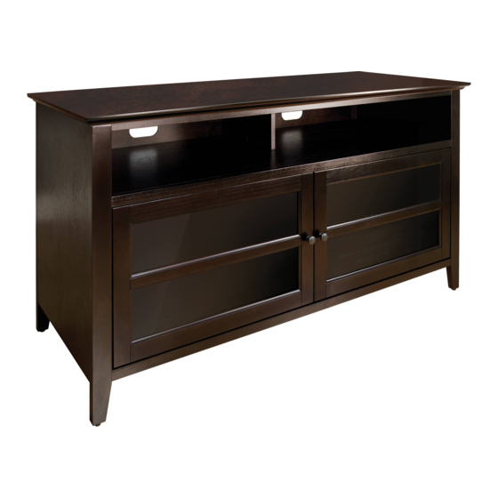
- Page 1 WAVs99144 WooD AuDIo/vIDeo CABIneT Assembly InstructIons...
- Page 2 fOR yOUR SAfETy, PLEASE fOLLOw ThESE PRECAUTIONS: ! Do not plAce Items on the shelVes WhIch exceeD the mAxImum WeIGht lImIts of 125 lbs. for top shelf, AnD 35 lbs. for eAch InterIor shelf. ! ALWAys reMove THe Tv AnD oTHer eQuIPMenT FroM THe FurnITure PrIor To MovInG THe AsseMBLeD unIT.
-
Page 3: Table Of Contents
Parts List Quantity Quantity Part Part Acm7 Acm1 Acm8 Acm2 Acm9 Acm3 Acm10 Acm4 Acm11 Acm5 Acm12 Acm6 Acm13... - Page 4 Parts List Quantity Part Acm14 Acm15 24 mm Acm16 Acm17 Acm18 Acm19...
- Page 5 assEMBLY iNstrUCtiONs n ote: 2 PeoPLe Are reCoMMenDeD To AsseMBLe THIs FurnITure. To AvoID DAMAGe DurInG AsseMBLy, IT sHouLD Be AsseMBLeD on A soFT surFACe. fig. 1 Acm17 Acm3 Acm9 Acm13 1. on a soft, flat surface, AttAch the Center Divider Panel (ACM9) to the Bottom Panel (ACM3) using two Wood Dowels (ACM17) as shown above.
-
Page 6: Acm2
fig. 2 fig. 2A Acm17 Acm2 Acm9 Acm17 fig. 2b 3. AttAch the Middle Interior shelf (ACM2) to the Center Divider Panel (ACM9) using two Wood Dowels (ACM17) as shown above. secure the Middle Interior shelf to the Divider Panel by flipping the two Locking Mechanisms in the Divider Panel as shown in Figs 2A and 2B. -
Page 7: Acm7
fig. 3 Acm7 Acm17 Acm2 Acm3 fig. 3b fig. 3A 4. AttAch the right side Panel (ACM7) as shown above. use four Wood Dowels (ACM17) as shown. 5. secure the side Panel (ACM7) by flipping the Locking Mechanisms on the underside of the Bottom shelf (ACM3), and the Locking Mechanisms on the underside of the Middle Interior shelf (ACM2) as shown in Figs 3A and 3B. - Page 8 fig. 4 Acm5 Acm3 Acm2 6. turn the cabinet upright with the help of an assistant. Carefully slIDe the Lower Back Panel (ACM5) into the grooves in the Bottom Panel (ACM3) and the Middle Interior shelf (ACM2). Make sure the Lower Back Panel is completely and properly in place before continuing.
- Page 9 fig. 5 Acm6 Acm17 Acm17 fig. 5A Acm3 fig. 5b 7. AttAch the Left side Panel (ACM6) as shown above. use four Wood Dowels (ACM17) as shown. 8. secure the side Panel (ACM6) by flipping the four Locking Mechanisms on the underside of the Bottom shelf (ACM3), and the four Locking Mechanisms on the underside of the Middle Interior shelf (ACM2) as shown in Figs 5A and 5B.
-
Page 10: Acm8
fig. 6 Acm8 Acm2 Acm17 fig. 6A fig. 6b 9. AttAch the Top shelf support Divider (ACM8) to the Middle Interior shelf (ACM2) using two Wood Dowels (ACM17) as shown. secure the support Divider to the Interior shelf by flipping the Locking Mechanism as shown in Figs 6A and 6B. - Page 11 fig. 7 Acm7 Acm4 Acm6 10. slIDe the upper Back Panel (ACM4) down into the grooves in the Left and right side Panels (ACM6, ACM7) as shown. NOTE (!): Make sure you position the Upper Back Panel with the Cable Management holes DOwN.
- Page 12 fig. 8 Acm17 Acm1 fig. 8A Acm8 Acm17 Acm7 Acm6 fig. 8b 11. With the help of an assistant, carefully plAce the Top shelf (ACM1) onto the cabinet assembly. Insert four Wood Dowels (ACM17) into the pre-drilled holes in the top edges of the Left and right side Panels (ACM6, ACM7), and two more Wood Dowels into the Top shelf support Divider (ACM8) as shown.
- Page 13 fig. 9 Acm4 Acm18 fig. 9A Acm5 13. secure the upper and Lower Back Panels (ACM4, ACM5) to the cabinet assembly using six short Thumbscrews (ACM18) as shown above. tIGhten each short Thumbscrew completely by hand (be careful not to overtighten!), then reMove the Grip-Tip portion of each Thumbscrew as shown in Fig 9A.
-
Page 14: Acm10
fig. 10 Acm16 Acm10 Acm10... -
Page 15: Acm11
fig. 11 Acm12 Acm11 Acm15 Acm14 Acm14... - Page 16 Acm2 fig. 12 Acm7 Acm12 Acm3 Acm6 Acm2 Acm11 fig. 12A Acm3 17. InstAll each Door (ACM11, ACM12) to the cabinet assembly. First, Insert the ToP Pin of the Door into the hole in the underside of the Middle Interior shelf (ACM2), then push the BoTToM Pin upward and sWInG the bottom portion of the Door into place as shown in Fig 12A. As you releAse the Bottom Pin, you should hear it click into place in the hole in the Bottom shelf (ACM3).
Need help?
Do you have a question about the WAVs99144 and is the answer not in the manual?
Questions and answers