Advertisement
The Series 605 Magnehelic
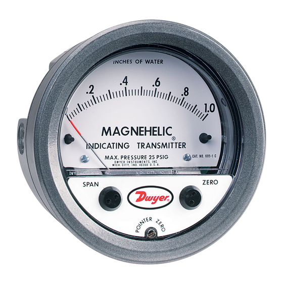
provides local indication on a large, easily read analog scale while also
converting that pressure into a standard two-wire, 4-20 mA signal for
ranges from 0-0.5 to 0-50˝ w.c. Positive, negative or differential air and
compatible gas pressure can be measured with accuracies as low as
±.5% of full scale. The basic mechanical components of the Series 605
Magnehelic
®
indicating transmitter are similar to those used in the pop-
ular, time-proven Magnehelic
STANDARD ACCESSORIES
Mounting ring
Snap ring
(4) 6-32 x 1-1/4 screws (panel mtg.)
(3) 6-32 x 5/16 screws (surface mtg.)
(2) Tubing to 1/8˝ NPT adapters
(2) 1/8˝ NPT plugs
Adjustment key
Range
Maximum
in w.c.
Pressure
Model
25 psi (1.7 bar)
605-00N
.05-0-.20
25 psi (1.7 bar)
605-11
.25-0-.25
25 psi (1.7 bar)
605-0
0-.50
25 psi (1.7 bar)
0-1.0
605-1
2 psi (13.79 kPa)
605-2
0-2.0
2 psi (13.79 kPa)
605-3
0-3.0
2 psi (13.79 kPa)
605-6
0-6.0
2 psi (13.79 kPa)
605-10
0-10
DWYER INSTRUMENTS, INC.
P.O. BOX 373 • MICHIGAN CITY, IN 46361, U.S.A.
Series 605 Magnehelic
Specifications - Installation and Operating Instructions
(3) #6-32 x 3/16 [4.76]
DP HOLES EQUALLY SPACED
ON A Ø4-1/8 [104.78] B.C.
FOR PANEL MOUNTING
Patent No. 4,890,497
®
Indicating Transmitter simultaneously
®
differential pressure gage.
Electrical
Mechanical
Accuracy +/-%
Accuracy +/-%
2
4
2
3
2
3
2
2
0.5
2
0.5
2
0.5
2
0.5
2
®
Differential Pressure Indicating Transmitter
1/8 FEMALE
23/32
NPT HIGH
[18.26]
PRESSURE
1
CONNECTION
[25.40]
1-3/4
30°
[44.45]
1/2 [12.70]
1-1/8
1/8 FEMALE NPT
[28.58]
LOW PRESSURE
11/16
CONNECTION
[17.46]
SPECIFICATIONS
GAGE SPECIFICATIONS
Service: Air and non-combustible, compatible gases.
Wetted Materials: Consult factory.
Accuracy: See chart.
Stability: ±1% F.S./yr.
Pressure Limits: See chart.
Temperature Limits: 20 to 120°F (-6.67 to 48.9°C).
Process Connections: 1/8˝ female NPT.
Size: 4˝ (101.6 mm) dial face, 5˝ (127 mm) O.D. x 2-11/16˝ (68.3 mm).
Weight: 1 lb, 12.6 oz (811 g).
Agency Approvals: CE.
TRANSMITTER SPECIFICATIONS
Accuracy: See chart (includes linearity, hysteresis, repeatability).
Temperature Limits: 20 to 120°F (-6.67 to 48.9°C).
Compensated Temperature Range: 32 to 120°F (0 to 48.9°C).
Thermal Effect: ±0.025% F.S./°F (0.045% F.S./°C).
Power Requirements: 10-35 VDC (2-wire).
Output Signal: 4 to 20 mA.
Zero and Span Adjustments: Protected potentiometers.
Loop Resistance: DC; 0-1250 ohms maximum.
Current Consumption: DC; 38 mA maximum.
Electrical Connections: Screw terminal block.
Mounting Orientation: Diaphragm in vertical position. Consult factory for
other position orientations.
Range
Maximum
in w.c.
Pressure
Model
20 psi (1.4 bar)
605-20
0-20.0
605-30
0-30
20 psi (1.4 bar)
20 psi (1.4 bar)
605-50
0-50
Range in Pa
605-60PA
0-60
25 psi (1.7 bar)
25 psi (1.7 bar)
605-125PA
0-125
605-250PA
0-250
25 psi (1.7 bar)
605-500PA
0-500
2 psi (13.79 kPa)
Phone: 219/879-8000 www.dwyer-inst.com
Fax: 219/872-9057
Bulletin E-68
(4) 6-32 HOLES
EQUALLY SPACED ON
2-1/16
A 5-1/8 [130.18] B.C.
[52.39]
2
FOR FLUSH MOUNTING
[50.80]
Ø4-47/64
1-1/4
[ 120.25]
[31.75]
Ø5
[127.00]
5/8 [15.88]
Ø4 [101.60]
PANEL MAX
2-1/2
FACE
3/16
[63.50]
5-1/2 [139.70]
[4.76]
O.D. MOUNTING
RING
Electrical
Mechanical
Accuracy +/-%
Accuracy +/-%
0.5
2
0.5
2
0.5
2
2
4
2
3
2
2
0.5
2
e-mail: info@dwyer-inst.com
Advertisement
Table of Contents

Subscribe to Our Youtube Channel
Related Manuals for Dwyer Instruments 605-00N


Summary of Contents for Dwyer Instruments 605-00N
- Page 1 2 psi (13.79 kPa) 605-6 0-6.0 605-250PA 0-250 25 psi (1.7 bar) 2 psi (13.79 kPa) 605-10 0-10 605-500PA 0-500 2 psi (13.79 kPa) DWYER INSTRUMENTS, INC. Phone: 219/879-8000 www.dwyer-inst.com P.O. BOX 373 • MICHIGAN CITY, IN 46361, U.S.A. Fax: 219/872-9057 e-mail: info@dwyer-inst.com...
- Page 2 4. MOUNTING: The Series 605 Transmitter may be either panel INSTALLATION mounted or surface mounted. 1. LOCATION: Select a location where the temperature of the unit will be between 20°F and 120°F. Distance from the receiver is limited SNAP RING GROOVE only by total loop resistance.
- Page 3 ELECTRICAL CONNECTIONS 1400 1300 MAXIMUM VALUE (1250) CAUTION: DO NOT EXCEED SPECIFIED SUPPLY VOLTAGE RAT- RL MAX = V - 10.0V 1200 INGS. PERMANENT DAMAGE NOT COVERED BY WARRANTY WILL 20 mA DC 1100 RESULT. THIS UNIT IS NOT DESIGNED FOR AC VOLTAGE OPERA- TION.
- Page 4 The minimum current requirement at a given voltage can be calculated by multiplying the number of units x 20 mA. In the example shown this would be 4 x 20 or 80 mA minimum. ©Copyright 2010 Dwyer Instruments, Inc. Printed in U.S.A. 2/10 FR# 01-440559-00 Rev. 4 DWYER INSTRUMENTS, INC.
Need help?
Do you have a question about the 605-00N and is the answer not in the manual?
Questions and answers