Table of Contents
Advertisement
Quick Links
PCE Americas Inc.
PCE Instruments UK Ltd.
711 Commerce Way
Units 12/13
Suite 8
Southpoint Business Park
Jupiter
Ensign way
FL-33458
Hampshire / Southampton
USA
United Kingdom, SO31 4RF
From outside US: +1
From outside UK: +44
Tel: (561) 320-9162
Tel: (0) 2380 98703 0
Fax: (561) 320-9176
Fax: (0) 2380 98703 9
info@pce-americas.com
info@pce-instruments.com
www.pce-instruments.com/english
www.pce-instruments.com
Manual
Roughness Tester PCE-RT 2200
Version 1.0
Date of creation: 12.05.2016
Date of last change: 02.12.2016
Advertisement
Table of Contents

Related Manuals for PCE Instruments PCE-RT 2200


Summary of Contents for PCE Instruments PCE-RT 2200
- Page 1 From outside UK: +44 Tel: (561) 320-9162 Tel: (0) 2380 98703 0 Fax: (561) 320-9176 Fax: (0) 2380 98703 9 info@pce-americas.com info@pce-instruments.com www.pce-instruments.com/english www.pce-instruments.com Manual Roughness Tester PCE-RT 2200 Version 1.0 Date of creation: 12.05.2016 Date of last change: 02.12.2016...
-
Page 2: Table Of Contents
Root mean square roughness Rq ....................19 7.2.3 Mean Roughness depth Rz ......................20 7.2.4 Total peak-to-valley height Rt ...................... 20 7.2.5 Choosing the sampling length ...................... 20 Disposal ......................... 21 Contact ........................21 PCE Instruments UK ........................ 21 PCE Americas .......................... 21... -
Page 3: Safety Notes
Please read this manual carefully and completely before you use the device for the first time. The device may only be used by qualified personnel and repaired by PCE Instruments personnel. There is no warranty of damages or injuries caused by non-observance of the manual. -
Page 4: Specifications
Humidity: < 90 RH Dimensions 141 x 55 x 40 mm Weight 400 g Delivery contents 1 x roughness tester PCE-RT 2200 (incl. battery) 1 x sensor 1 x sensor protection 1 x adjustable support 1 x screw driver 1 x calibration standard... -
Page 5: Optional Accessories
Manual Optional accessories PCE-RP-100 Spare sensor PCE-RP-110 Sensor for curved surfaces (curvature radius > 3mm) PCE-RP-120 Sensor for holes (> Ø 2 mm) PCE-RP-131 Sensor for grooves (width: min. 3 mm; depth: max. 10 mm) PCE-RTS 520 Test stand PCE-RTS 620 Test stand System description Device... -
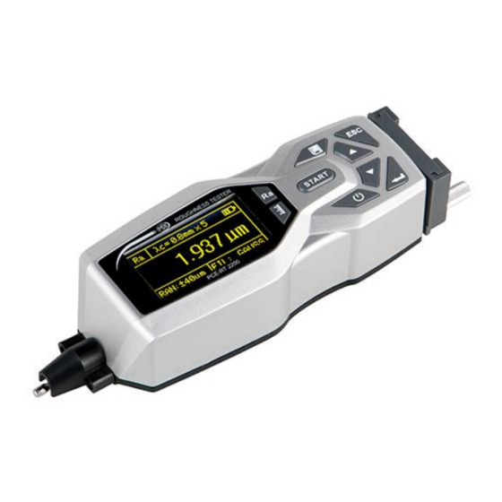
Page 6: Display And Function Keys
Sensor Connection Stylus Main body Skid Protective tube Display and function keys Display Measuring length Range Sampling length Filter Multiplier Measuring unit Battery status... -
Page 7: Optional Accessories
Manual Function keys Button Name Function Press and hold for 2 seconds to turn the device “Power” button on/off. “Stylus position” button Press to open stylus position display. “Start” button Press to start a measurement. “Parameter selection” button Press to display more measuring parameters. “Save/print”... - Page 8 Manual Sensor for grooves (PCE-RP-131) The sensor PCE-RP-131 is suited for measuring surfaces in grooves with a minimum width of 3 mm and a maximum depth of 10 mm. We recommend using the sensor in combination with a PCE-RTS 620 test stand.
-
Page 9: Getting Started
Manual Getting started Charging the battery When the battery voltage is low, a low battery indication appears on the display . In this case, please recharge the battery as soon as possible. The battery is charged via the USB interface of the device. -
Page 10: Operation
Manual Mounting the adjustable support Screw on the adjustable support as seen on the picture below. Adjustable support Screws Operation Taking a measurement Switch the Power switch into the “On” position and press and hold the “Power” button for 2 seconds to turn on the device. - Page 11 Manual Stylus Position Press the “Stylus position” button to go to the stylus position screen. The stylus position is ideal when the arrow indicates “0”. Use the adjustable support to adjust the stylus position. Press the “Stylus position” button again to return to the main screen. Starting a measurement To start a measurement, press the “Start”...
-
Page 12: Further Functions
Manual Further functions 5.2.1 Saving of measured data To save the measured data, simply press the “Save/print” button in the main screen after a measurement. -
Page 13: Printing Of Measured Data
Manual 5.2.2 Printing of measured data If a printer is connected to the device, you can also print out the readings. To do so, press the “Parameter selection” button and the “Save/print” button afterwards. The data from the last measurement is printed out. -
Page 14: View Saved Data
Manual 5.2.3 View saved data To view the saved data, press the “Enter/menu” button on the main screen to open the menu. Then to select option “2. Recorder” and press the “Enter/menu” button use the arrow buttons again to confirm. Next, select option “1. -
Page 15: Settings
Manual Settings Press the “Enter/menu” button to open the menu. 5.3.1 Measurement settings to select option “1. Parameter” and press the “Enter/menu” button Use the arrow buttons to confirm. Now you get to the measurement settings. To change a parameter, select it and press the “Enter/menu” button to change the displayed option. -
Page 16: Print Settings
Manual 5.3.3 Print settings to select option “4. Print” and press the “Enter/menu” button Use the arrow buttons confirm. Now you get to the print settings. Here you can select, which parameters shall be printed out. To do so, select the particular parameters by and press the „Enter/menu“... -
Page 17: Calibration
Manual Calibration We recommend calibrating the device before each use, especially if it has not been used in a long time. To do so, use the provided calibration standard. Take a measurement on the calibration standard (see chapter 5.1). If the reading deviates from the properties of the calibration standard by more than the accuracy of the device (±... -
Page 18: Additional Information
Manual Additional Information Filter information Filtered profile: The unfiltered primary profile is filtered. The roughness profile (filtered profile) is separated from the waviness profile. D-P (direct profile): Adopt centreline from least square algorithm. RC filter: analogue 2 RC filter with phase difference PC-RC filter: RC filter with phase correction Gauss filter:... -
Page 19: Measuring Parameters
Manual PC-RC filter Pre- Measuring Approach Post- length travel path travel Traversing length Origin Measuring parameters 7.2.1 Arithmetical mean deviation of the roughness profile Ra Ra is the arithmetic mean of the absolute values of profile deviation from the centreline within the measuring length. -
Page 20: Mean Roughness Depth Rz
Manual 7.2.3 Mean Roughness depth Rz Rz is the sum of the height Zp of the highest profile peak from the centreline and depth Zv of the deepest profile valley from the centreline within the measuring length. 7.2.4 Total peak-to-valley height Rt Rt is the sum of the height of the highest peak Zp and the depth of the deepest valley Zv over the measuring length. -
Page 21: Disposal
In order to comply with the EU directive 2012/19/EU we take our devices back. We either re-use them or give them to a recycling company which disposes of the devices in line with law. If you have any questions, please contact PCE Instruments. Contact If you have any questions about our range of products or measuring instruments please contact PCE Instruments.
Need help?
Do you have a question about the PCE-RT 2200 and is the answer not in the manual?
Questions and answers