Table of Contents

Related Manuals for GE Multilin 345

Summary of Contents for GE Multilin 345
- Page 1 Grid Solutions Transformer Protection System Transformer protection and control Instruction manual 345 revision: 2.3x Manual P/N: 1601-9098-AF GE publication code: GEK-113568P E83849 LISTED *1601-9098-AF* IND.CONT. EQ. 52TL...
- Page 2 The contents of this manual are the property of GE Multilin Inc. This documentation is furnished on license and may not be reproduced in whole or in part without the permission of GE Multilin. The content of this manual is for informational use only and is subject to change without notice.
- Page 3 GENERAL SAFETY PRECAUTIONS - 345 Note • Failure to observe and follow the instructions provided in the equipment manual(s) could cause irreversible damage to the equipment and could lead to property damage, personal injury and/or death. • Before attempting to use the equipment, it is important that all danger and caution indicators are reviewed.
- Page 4 Safety words and definitions The following symbols used in this document indicate the following conditions Indicates a hazardous situation which, if not avoided, will result in death or serious Note injury. Indicates a hazardous situation which, if not avoided, could result in death or serious Note injury.
-
Page 5: Table Of Contents
Table of Contents 1. INTRODUCTION Overview ..........................1 - 1 Description of the 345 Transformer Protection System......1 - 2 345 order codes......................1 - 7 Specifications........................1 - 9 Password security........................1 - 9 Protection..........................1 - 9 Metering............................1 - 11 Data capture ..........................1 - 12... - Page 6 Transformer Differential and Restraint Currents ..........4 - 7 Transformer Thermal Capacity ..................4 - 8 Current Demand 1(2)......................4 - 8 Clear current demand 1 (2)....................4 - 9 A3 Records.........................4 - 10 Event records......................... 4 - 10 TOC-2 345 TRANSFORMER PROTECTION SYSTEM – INSTRUCTION MANUAL...
- Page 7 Thermal Overload (49)......................6 - 52 Time overcurrent curves....................6 - 56 Phase timed overcurrent (51P)..................6 - 60 Phase instantaneous overcurrent (50P)..............6 - 63 Ground timed overcurrent (51G/SG)................6 - 65 Ground instantaneous overcurrent (50G/SG) ............6 - 68 345 TRANSFORMER PROTECTION SYSTEM – INSTRUCTION MANUAL TOC-3...
- Page 8 Out-of-service maintenance ..................7 - 19 Unscheduled maintenance (system interruption)..........7 - 19 A. APPENDIX Warranty ..........................A - 1 Repairs ..........................A - 2 Change Notes........................A - 3 Manual Revision history....................A - 3 TOC-4 345 TRANSFORMER PROTECTION SYSTEM – INSTRUCTION MANUAL...
-
Page 9: Introduction
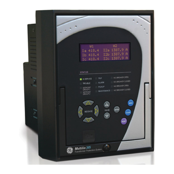
Chapter 1: Introduction Introduction Overview The 345 is a microprocessor-based relay for primary and backup protection of small to medium size distribution transformers. The relay provides advanced algorithms for automatic magnitude and phase compensation for more than twenty types of two-... -
Page 10: Description Of The 345 Transformer Protection System
DESCRIPTION OF THE 345 TRANSFORMER PROTECTION SYSTEM CHAPTER 1: INTRODUCTION Description of the 345 Transformer Protection System Relay functions are controlled by two processors: a Freescale MPC5554 32-bit microprocessor measures all analog signals and digital inputs and controls all output relays;... -
Page 11: Transformer Protection System – Instruction Manual
CHAPTER 1: INTRODUCTION DESCRIPTION OF THE 345 TRANSFORMER PROTECTION SYSTEM Figure 1-1: Functional block diagram Winding 1 Winding 2 50BF 50BF 51_2 51_2 50_2 50_2 Calculate Calculate Restraint Current Differential Currents 50/87 Calculate BLOCK Harmonics 2nd and 5th Metering Transient Recorder... - Page 12 DESCRIPTION OF THE 345 TRANSFORMER PROTECTION SYSTEM CHAPTER 1: INTRODUCTION Table 1-1: ANSI device numbers and functions ANSI Code 61850 Logical Node Description PTTR1 Thermal Overload rtdGGIO6 Temperature Monitoring 50/87 insPDIF1 Instantaneous Differential 50_2 ngseqPIOC1, Negative Sequence Instantaneous Overcurrent ngseqPIOC2...
- Page 13 Virtual Inputs (32) Virtual Outputs (32) The 345 relay has two identical setpoint groups, with the same set of protection elements. By default setpoint group 1 will be active. Setpoint group 2 can be activated by programming the conditions under S4 Control/Change Setpoint Group menu.
- Page 14 DESCRIPTION OF THE 345 TRANSFORMER PROTECTION SYSTEM CHAPTER 1: INTRODUCTION ACTUAL VALUES ACTUAL VALUES A1 STATUS COMMANDS QUICK SETUP A2 METERING SETPOINTS A3 RECORDS MAINTENANCE A4 TARGET MESSAGES 897756A3.cdr QUICK SETUP RELAY STATUS SETPOINTS S1 RELAY SETUP NOMINAL FREQUENCY S2 SYSTEM SETUP...
-
Page 15: 345 Order Codes
CHAPTER 1: INTRODUCTION 345 ORDER CODES 345 order codes The information to specify a 345 relay is provided in the following Order Code figure. Figure 1-3: Order Codes – * Interface 345 Transformer Protection Relay English without programmable LEDs User... - Page 16 CHAPTER 1: INTRODUCTION Empty chassis The 345 protection relay chassis used with a drawout relay is available separately, for use as a partial replacement or in test environments. Many features are supported by the cards and ports within the chassis, as is reflected in the chassis order code.
-
Page 17: Specifications
Curve Multiplier:........... 0.05 to 50.00 in steps of 0.01 Reset Time: ............Instantaneous, Linear Curve Timing Accuracy: ........±3% of expected inverse time or 1 cycle, whichever is greater, from pickup to operate Level Accuracy:............ per CT input 345 TRANSFORMER PROTECTION SYSTEM – INSTRUCTION MANUAL 1–9... - Page 18 Level Accuracy: ........... per current inputs TRANSFORMER INSTANTANEOUS DIFFERENTIAL PROTECTION (50/87) Pickup Level: ............3.00 to 20.00xCT in steps of 0.01xCT Dropout Level:............95% of Pickup Operate Time: ............<30 ms Level Accuracy: ........... per current inputs 1–10 345 TRANSFORMER PROTECTION SYSTEM – INSTRUCTION MANUAL...
-
Page 19: Metering
CT withstand: ............1 second at 100 A (1 A option) 1 second at 400 A (5 A or universal CT option) 2 seconds at 40 × rated current continuous at 3 × rated current 345 TRANSFORMER PROTECTION SYSTEM – INSTRUCTION MANUAL 1–11... -
Page 20: Data Capture
Supported operations: ........AND, OR, NOR, NAND, XOR, XNOR, Pickup / Dropout timers Pickup timer: ............0 to 60000 ms in steps of 1 ms Dropout timer:............0 to 60000 ms in steps of 1 ms 1–12 345 TRANSFORMER PROTECTION SYSTEM – INSTRUCTION MANUAL... - Page 21 Low Temperature Pickup: .......-40°C to 20°C in steps of 1°C Time Delay:............1 to 60 min in steps of 1 min Temperature Dropout:........Configurable 90 to 98% of pickup Temperature Accuracy: ........±10°C Timing Accuracy:..........±1 second 345 TRANSFORMER PROTECTION SYSTEM – INSTRUCTION MANUAL 1–13...
-
Page 22: Monitoring
Range:..............-50 to +250 Accuracy: ............... ±3 Lead Resistance: ..........25 Ohm max per lead RTD Trouble Alarm: ..........<-50 or >250 RTD Inputs Available: ........12 maximum with the RMIO option connected 1–14 345 TRANSFORMER PROTECTION SYSTEM – INSTRUCTION MANUAL... -
Page 23: Outputs
125 to 250 VDC Range: ..............60 to 300 VAC (50 and 60 Hz) 84 to 250 VDC Ride-through time: ..........35 ms LOW RANGE POWER SUPPLY Nominal:..............24 to 48 VDC Range: ..............20 to 60 VDC 345 TRANSFORMER PROTECTION SYSTEM – INSTRUCTION MANUAL 1–15... -
Page 24: Communications
Maximum input power:........-11.8 dBm Typical distance: ..........2 km (1.25 miles) Duplex:..............half/full Product type: ............Class 1 Laser product Standard specification:........Compliant with USB 2.0 Data transfer rate: ..........115 kbps 1–16 345 TRANSFORMER PROTECTION SYSTEM – INSTRUCTION MANUAL... -
Page 25: Testing And Certification
(80 MHz-1 GHz with 1 KHz sine and 80% AM modulation) IEEE / ANSI C37.90.3 8KV CD/ 15KV AD UL 508 e83849 NKCR Safety UL C22.2-14 e83849 NKCR7 UL 1053 e83849 NKCR 345 TRANSFORMER PROTECTION SYSTEM – INSTRUCTION MANUAL 1–17... -
Page 26: Physical
NON-DRAWOUT UNIT Weight (net): ............2.9 kg (6.4 lbs) Weight (gross): ............. 4.0 kg (8.6 lbs) DRAWOUT UNIT Weight (net): ............3.9 kg (8.6 lbs) Weight (gross): ............. 5.0 kg (11.0 lbs) 1–18 345 TRANSFORMER PROTECTION SYSTEM – INSTRUCTION MANUAL... -
Page 27: Environmental
Operating up to 95% (non condensing) @ 55 C (As per IEC60068-2-30 Variant 2, 6 days) Altitude: 2000 m (max) Pollution Degree: Overvoltage Category: Ingress Protection: IP54 Front, IP20 cover (optional) Noise: 0 dB 345 TRANSFORMER PROTECTION SYSTEM – INSTRUCTION MANUAL 1–19... - Page 28 SPECIFICATIONS CHAPTER 1: INTRODUCTION 1–20 345 TRANSFORMER PROTECTION SYSTEM – INSTRUCTION MANUAL...
-
Page 29: Installation
Dimensions The dimensions of the 345 are on the following pages. Additional dimensions for mounting and panel cutouts are shown in the following sections. 345 TRANSFORMER PROTECTION SYSTEM – INSTRUCTION MANUAL... - Page 30 MECHANICAL INSTALLATION CHAPTER 2: INSTALLATION Figure 2-1: 345 dimensions - Drawout unit 1 0 7 2–2 345 TRANSFORMER PROTECTION SYSTEM – INSTRUCTION MANUAL...
-
Page 31: Product Identification
(202.7mm) (173.2mm) 6.23" (158.2mm) Product identification The product identification label is located on the side panel of the 345 . This label indicates the product model, serial number, and date of manufacture. Figure 2-3: 345 Product label Technical Support: Multilin... -
Page 32: Mounting
Figure 2-4: Standard panel mounting - Drawout 8 - 32X3/8IN P/HD PHIL BLK GE PART # 1408-0306; (QTY:8) TIGHTENING TORQUE: 15 IN LB 2–4 345 TRANSFORMER PROTECTION SYSTEM – INSTRUCTION MANUAL... - Page 33 Figure 2-5: Standard Panel mounting - Non-drawout 8-32 x 3/8" P/HD PHIL BLK GE P/N 1408-0306 (QTY:8) Tightening Torque: 15 in-lb (1.7 Nm) Panel with Cutout NDO unit Figure 2-6: Depth Reducing collar (optional) 345 TRANSFORMER PROTECTION SYSTEM – INSTRUCTION MANUAL 2–5...
- Page 34 If added security is required, bend the retaining "V"tabs outward, to about 90°. These tabs are located on the sides of the case and appear as shown above. The relay can now be inserted and can be panel wired. 2–6 345 TRANSFORMER PROTECTION SYSTEM – INSTRUCTION MANUAL...
- Page 35 Figure 2-9: RMIO - DIN rail mounting - Base & Expansion units SNAP-IN THE DIN CLIPS (QTY: 4) FOR DIN RAIL MOUNTING 0.30” (7,6 mm) 1.38” (35,1 mm) DIN 3 RAIL 853726A1.CDR 345 TRANSFORMER PROTECTION SYSTEM – INSTRUCTION MANUAL 2–7...
- Page 36 [58.04 mm] EXPANSION UNIT OUTLINE #6-32 THREADED HOLE 1.500” QTY: 2 [38.10 mm] #6-32X1/2 FT FLAT HEAD PHIL ZINC 853755A1.cdr QTY: 2; (SUPPLIED); GE PART # 1406-0117 TIGHTENING TORQUE: 10 lb. in. 2–8 345 TRANSFORMER PROTECTION SYSTEM – INSTRUCTION MANUAL...
-
Page 37: Drawout Unit Withdrawal And Insertion
PUSH THE HANDLE DOWN AND TIGHTEN KEEP THE HANDLE IN ITS ROTATED THE SCREW UNTIL THE HANDLE IS PARALLEL POSITION UNTIL THE DRAW-OUT UNIT WITH THE FRONT PANEL SURFACE IS INSERTED COMPLETELY 345 TRANSFORMER PROTECTION SYSTEM – INSTRUCTION MANUAL 2–9... -
Page 38: Ip20 Cover (Optional)
Before attaching the cover, remove the old labels from the device (see item#2 and item#3) and replace them with the new labels from the retrofit kit. Attach the cover as described in the previous section. 2–10 345 TRANSFORMER PROTECTION SYSTEM – INSTRUCTION MANUAL... -
Page 39: Electrical Installation
CHAPTER 2: INSTALLATION ELECTRICAL INSTALLATION Electrical installation This section describes the electrical installation of the 345 system, including typical wiring diagrams and terminal identification. 345 TRANSFORMER PROTECTION SYSTEM – INSTRUCTION MANUAL 2–11... -
Page 40: Typical Wiring Diagrams
TYPE B 5 AUXILIARY 4 WIRE USB Rear Panel 6 AUXILIARY COMMUNICATIONS ETHERNET RJ45 mTRJ IRIG-B RS485 10/100 BASE-T100 BASE-FX 7 CRITICAL 4 WIRE ETHERNET FAILURE OPTIONAL F5 F4 F3 RELAY GROUND 897744.CDR 2–12 345 TRANSFORMER PROTECTION SYSTEM – INSTRUCTION MANUAL... - Page 41 TYPE B 5 AUXILIARY 4 WIRE USB Rear Panel 6 AUXILIARY COMMUNICATIONS ETHERNET RJ45 mTRJ RS485 IRIG-B 10/100 BASE-T100 BASE-FX 7 CRITICAL 4 WIRE ETHERNET FAILURE OPTIONAL RELAY C5 C4 C3 GROUND 897745.CDR 345 TRANSFORMER PROTECTION SYSTEM – INSTRUCTION MANUAL 2–13...
-
Page 42: 345 Terminal Identification
This is to ensure the adjacent lower terminal block does not interfere with the lug body. NOTE Figure 2-16: Orient the lugs correctly... SCREW WASHER LOWER TERMINAL TERMINAL BLOCK DIVIDER Figure 2-17: CORRECT INSTALLATION METHOD 2–14 345 TRANSFORMER PROTECTION SYSTEM – INSTRUCTION MANUAL... - Page 43 CHAPTER 2: INSTALLATION ELECTRICAL INSTALLATION Figure 2-18: INCORRECT INSTALLATION METHOD (lower lug reversed) 345 TRANSFORMER PROTECTION SYSTEM – INSTRUCTION MANUAL 2–15...
- Page 44 ■ AUX 6 N/O W2 PHASE C CT INPUT COM CRIT FAIL N/C W2 PHASE C CT ■ CRIT FAIL COM W2 GND CT CHASSIS GND CRIT FAIL N/O W2 GND CT 2–16 345 TRANSFORMER PROTECTION SYSTEM – INSTRUCTION MANUAL...
-
Page 45: Wire Range
Suggested wiring screw tightening torque, tighten to 12 in-lb (1.35 N-m). • The uncovered communications cable shield connected to the common terminal should not exceed 1” (2.5 cm) for proper EMC shielding of the communications cable. 345 TRANSFORMER PROTECTION SYSTEM – INSTRUCTION MANUAL 2–17... -
Page 46: Rmio Module Installation
Figure 2-21: RMIO unit showing 2 IO_G modules Figure 2-22: RMIO terminal identification with 4 IO_G modules IO_G IO_G IO_G IO_G Common 896750.cdr 2–18 345 TRANSFORMER PROTECTION SYSTEM – INSTRUCTION MANUAL... -
Page 47: Phase Sequence And Transformer Polarity
SCADA/PLC/COMPUTER ONLY OR THE MM300 ONLY (*) TERMINATING IMPEDANCE AT EACH END (typically 120 ohms and 1 nF) F5, F7, and F8 refer to terminals shown on the above 345 Terminal Identification diagrams. NOTE: NOTE Phase sequence and transformer polarity For correct operation of the relay features, the user must follow the instrument transformer polarities, shown in the Typical Wiring Diagram. -
Page 48: Ground And Sensitive Ground Ct Inputs
GROUND CURRENT INPUT GROUND CURRENT INPUT WITH ZERO SEQUENCE CT WITH RESIDUAL CONNECTION 897730A1.CDR For Winding 2 ground CT, use relay terminals D12-E12 in the same wiring configuration as shown above for Winding 1. 2–20 345 TRANSFORMER PROTECTION SYSTEM – INSTRUCTION MANUAL... -
Page 49: Zero Sequence Ct Installation
96 strands of number 34 AWG should be used. Belden catalog number 8660 is suitable. Isolate power prior to servicing. CAUTION: An external switch, circuit breaker, or other protective device must be connected near to NOTE: the equipment. NOTE 345 TRANSFORMER PROTECTION SYSTEM – INSTRUCTION MANUAL 2–21... -
Page 50: Contact Inputs
Terminal C11. The maximum external source voltage for this arrangement is 300 V DC. Figure 2-27: Wet contact connections Wet Contact Connection RELAY Contact Input 1 V DC Power Supply Contact Input Common C11 LOGICIN.CDR 2–22 345 TRANSFORMER PROTECTION SYSTEM – INSTRUCTION MANUAL... -
Page 51: Trip1 And Trip2 Output Relays
ELECTRICAL INSTALLATION Trip1 and Trip2 output relays The 345 relay is equipped with seven electromechanical relays: two special relays designed for Winding 1 Breaker trip and Winding 2 Breaker trip, four general purpose relays (Auxiliary Relays 3 to 6), and a Critical Failure relay. The special purpose relays have fixed operating characteristics and the general purpose relays can be configured by the user. - Page 52 Figure 2-29: Relay #1 Trip and Relay #2 Trip circuits with voltage monitoring DC + DC + Output Relay 1 (TRIP) Output Relay 2 (TRIP) External External jumper jumper contact contact Trip Trip Coil Coil 897786.cdr DC - DC - 2–24 345 TRANSFORMER PROTECTION SYSTEM – INSTRUCTION MANUAL...
-
Page 53: Serial Communications
CAUTION: that the common terminals of each RS485 port are tied together and grounded only once, at the master or at the 345 . Failure to do so may result in intermittent or failed communications. The source computer/PLC/SCADA system should have similar transient protection devices installed, either internally or externally. -
Page 54: Irig-B
DC level shift or amplitude modulated (AM) form. The type of form is auto-detected by the 345 relay. Third party equipment is available for generating the IRIG-B signal; this equipment may use a GPS satellite system to obtain the time reference so that devices at different geographic locations can also be synchronized. -
Page 55: Interfaces
• Interfacing via the EnerVista 3 Series Setup software. This section provides an overview of the interfacing methods available with the 345 using the relay control panels and EnerVista 3 Series Setup software. For additional details on interface parameters (for example, settings, actual values, etc.), refer to the individual chapters. -
Page 56: Interfaces Front Control Panel Interface
W1 BREAKER OPEN TROUBLE ALARM W1 BREAKER CLOSED SETPOINT PICKUP W2 BREAKER OPEN GROUP 1 SETPOINT MAINTENANCE W2 BREAKER CLOSED GROUP 2 △ ▲ MENU ◁ ▷ ENTER ▼ ESCAPE ▽ RESET 897351A1.cdr 3–2 345 TRANSFORMER PROTECTION SYSTEM – INSTRUCTION MANUAL... -
Page 57: Description
CHAPTER 3: INTERFACES FRONT CONTROL PANEL INTERFACE Figure 3-2: 345 Feeder Protection System Front Panel - Programmable LEDs GE Multilin 345 Transformer Protection System IN SERVICE TROUBLE TRIP ALARM MENU ENTER ESCAPE RESET 897841A1.cdr Description The relay front panel provides an interface with a liquid crystal display, LED status indicators, control keys, and a USB program port. -
Page 58: Display
Any trip, alarm, or pickup is displayed immediately, automatically overriding the default message. Working with the The 345 display messages are organized into a Main Menu, pages, and sub-pages. There Keypad are four main menus labeled Actual Values, Quick Setup, Setpoints, and Maintenance. -
Page 59: Led Status Indicators - Front Panel With Non-Programmable Leds
1 will be active. The protection elements from group 2 will be inactive. The settings for each protection element can be edited and displayed regardless of the active group. 345 TRANSFORMER PROTECTION SYSTEM – INSTRUCTION MANUAL 3–5... - Page 60 W2 BREAKER CLOSED: Red/Green/Orange/Off – programmable color, default Green This LED is lit when the winding 2 breaker is detected closed. Refer to M7 Testing for information on testing LED status indicators. NOTE: NOTE 3–6 345 TRANSFORMER PROTECTION SYSTEM – INSTRUCTION MANUAL...
-
Page 61: Led Status Indicators - Front Panel With Programmable Leds
LED 7: Red/Orange/Green/Off - programmable source signal, type, and color • LED 8: Red/Orange/Green/Off - programmable source signal, type, and color Refer to M7 Testing for information on testing LED status indicators. NOTE: NOTE 345 TRANSFORMER PROTECTION SYSTEM – INSTRUCTION MANUAL 3–7... -
Page 62: Relay Messages
State: Operate This line from the display shows the state of the element: Pickup, Operated, Alarm. Phase: A The last line from the display shows the phase that picked up or operated. 3–8 345 TRANSFORMER PROTECTION SYSTEM – INSTRUCTION MANUAL... -
Page 63: Self-Test Errors
ALERT : error between Instantaneously Ethernet connection. Ethernet Link 345 and Network. Check health of the Fail network. Check status of external routers and switches. Check that IP settings are not 0.0.0.0 345 TRANSFORMER PROTECTION SYSTEM – INSTRUCTION MANUAL 3–9... - Page 64 INSTALLATION INSTALLATION setting to programmed state. setting is altered. "Programmed". * Failure is logged after the detection of 5 consecutive failures - that is after 25 seconds 3–10 345 TRANSFORMER PROTECTION SYSTEM – INSTRUCTION MANUAL...
-
Page 65: Flash Messages
This flash message is displayed in response to executing a command: ON, OFF, YES, NO, etc. INVALID PASSWORD This flash message appears upon an attempt to enter an incorrect password, as part of password security. 345 TRANSFORMER PROTECTION SYSTEM – INSTRUCTION MANUAL 3–11... -
Page 66: Software Setup
Although settings can be entered manually using the control panel keys, a PC can be used to download setpoints through the communications port. The EnerVista 3 Series Setup software is available from GE Multilin to make this as convenient as possible. With EnerVista 3 Series Setup running, it is possible to: •... -
Page 67: Hardware And Software Requirements
The EnerVista 3 Series Setup software can run without a 345 connected to the computer. In this case, settings may be saved to a file for future use. If a 345 is connected to a PC and communications are enabled, the 345 can be programmed from the setting screens. In addition, measured values, status and trip messages can be displayed with the actual value screens. - Page 68 USB driver will be loaded into the computer, and the installation program will automatically create icons and add EnerVista 3 Series Setup software to the Windows start menu. The 345 device will be added to the list of installed IEDs in the EnerVista Launchpad window, as shown below. 3–14...
- Page 69 If you are going to communicate from your computer to the 345 Relay using the USB port: 10. Plug the USB cable into the USB port on the 345 Relay then into the USB port on your computer. 11. Launch EnerVista 3 Series Setup from LaunchPad.
-
Page 70: Upgrading The Software
(for USB communications) or to the RS485 terminals on the back of the device (for RS485 communications). This example demonstrates an USB connection. For RS485 communications, the GE Multilin F485 converter will be required. Refer to the F485 manual for additional details. To configure the relay for Ethernet communications, see Configuring Ethernet Communications below. -
Page 71: Using The Quick Connect Feature
CHAPTER 3: INTERFACES SOFTWARE SETUP Click the Read Order Code button to connect to the 345 device and upload the order code. Click OK when the relay order code has been received. The new device will be added to the Site List window (or Online window) located in the top left corner of the main EnerVista 3 Series Setup window. - Page 72 As indicated by the window, the "Quick Connect" feature can quickly connect the EnerVista 3 Series Setup software to a 345 front port if the USB is selected in the interface drop-down list. Select "SR3 Relay" and press the Connect button. Ethernet can also be used as the interface for Quick Connect as shown above.
-
Page 73: Configuring Ethernet Communications
Enter the IP address, slave address, and Modbus port values assigned to the 345 relay (from the S1 RELAY SETUP > COMMUNICATIONS > ETHERNET menu). Click the Read Order Code button to connect to the 345 and upload the order code. If a communications error occurs, ensure that the Ethernet communication values correspond to the relay setting values. -
Page 74: Connecting To The Relay
The Front Panel settings can now be edited, printed, or changed. Other setpoint and command windows can be displayed and edited in a similar manner. "Actual Values" windows are also available for display. These windows can be arranged, and resized at will. 3–20 345 TRANSFORMER PROTECTION SYSTEM – INSTRUCTION MANUAL... -
Page 75: Working With Setpoints And Setpoint Files
In the Setpoint > System Setup > Transformer dialog box, click on Save to save the values into the 345 . Click YES to accept any changes and exit the window. Click Restore to retain previous values. Click Default to restore Default values. -
Page 76: Setting Programmable Leds
In the Setpoint > S1 Relay Setup > Front Panel dialog box, click Save to save the values into the 345 . Click YES to accept any changes. Click Restore to retain previous values. Click Default to restore Default values (all LEDs Off and colors Orange). -
Page 77: File Support
Control • Inputs/Outputs Factory default values are supplied and can be restored after any changes. The EnerVista 3 Series Setup displays relay setpoints with the same hierarchy as the front panel display. 345 TRANSFORMER PROTECTION SYSTEM – INSTRUCTION MANUAL 3–23... -
Page 78: Downloading And Saving Setpoint Files
SOFTWARE SETUP CHAPTER 3: INTERFACES Downloading and Back up a copy of the in-service settings for each commissioned 345 unit, so as to revert saving setpoint files to the commissioned settings after inadvertent, unauthorized, or temporary setting changes are made, after the settings default due to firmware upgrade, or when the unit has to be replaced. -
Page 79: Creating A New Setpoint File
Select the file name and path to store the file, or select any displayed file name to replace an existing file. All 345 setpoint files should have the extension ‘SR3’ (for example, ‘feeder1.SR3’). Click OK to complete the process. Once this step is completed, the new file, with a complete path, will be added to the EnerVista 3 Series Setup software environment. -
Page 80: Printing Setpoints And Actual Values
1.20, change the setpoint file revision to “1.4x”. Discontinued order codes may be included to maintain back-compatibility of setpoint files. NOTE: For current order codes, refer to the GE Multilin website at http:// www.gegridsolutions.com/multilin. -
Page 81: Printing Actual Values From A Connected Device
Establish communications with the desired 345 device. From the main window, select the Online > Print Device Information menu item The Print/Export Options dialog box will appear. Select Actual Values in the upper section and select either Include All Features (for a complete list) or Include Only Enabled Features (for a list of only those features which are currently used) in the filtering section and click OK. -
Page 82: Loading Setpoints From A File
Uninstalling files and The unit can be decommissioned by turning off the power to the unit and disconnecting the wires to it. Files can be cleared after uninstalling the EnerVista software or 345 device, clearing data for example to comply with data security regulations. On the computer, settings files can be identified by the .sr3 extension. -
Page 83: Upgrading Relay Firmware
Message,” indicating that it is in upload mode. While the file is being loaded into the 345 , a status box appears showing how much of the new firmware file has been transferred and the upgrade status. The entire transfer process takes approximately 10 minutes. - Page 84 SOFTWARE SETUP CHAPTER 3: INTERFACES The EnerVista 3 Series Setup software will notify the user when the 345 has finished loading the file. Carefully read any displayed messages and click OK to return the main screen. Cycling power to the relay is recommended after a firmware upgrade.
-
Page 85: Advanced Enervista 3 Series Setup Features
• Click on Trigger Waveform to trigger a waveform capture. Waveform file numbering starts with the number zero in the 345 , so that the maximum trigger number will always be one less than the total number of triggers available. - Page 86 • From the window main menu bar, press the Preference button to open the COMTRADE Setup page, in order to change the graph attributes. 3–32 345 TRANSFORMER PROTECTION SYSTEM – INSTRUCTION MANUAL...
- Page 87 The Waveform Capture window will reappear based on the selected graph attributes. To view a vector graph of the quantities contained in the waveform capture, press the Vector Display button to display the following window: 345 TRANSFORMER PROTECTION SYSTEM – INSTRUCTION MANUAL 3–33...
-
Page 88: Protection Summary
• view the enable/disable status of Control Elements • navigate to the respected Protection Element screen on a button click. An example of the Protection Summary screen follows: 3–34 345 TRANSFORMER PROTECTION SYSTEM – INSTRUCTION MANUAL... - Page 89 CHAPTER 3: INTERFACES SOFTWARE SETUP 345 TRANSFORMER PROTECTION SYSTEM – INSTRUCTION MANUAL 3–35...
-
Page 90: Password Security
CHAPTER 3: INTERFACES Password security Password security is an optional feature of the 345 which can be setup using the EnerVista 3 Series Setup software. The password system has been designed to facilitate a hierarchy for centralized management. This is accomplished through a Master level access password which can be used for resetting lower level access passwords and higher level privileged operations. - Page 91 The access level turns off after a period of 5 minutes of inactivity, if control power is cycled, or if the user enters an incorrect password. 345 TRANSFORMER PROTECTION SYSTEM – INSTRUCTION MANUAL 3–37...
- Page 92 SOFTWARE SETUP CHAPTER 3: INTERFACES 3–38 345 TRANSFORMER PROTECTION SYSTEM – INSTRUCTION MANUAL...
-
Page 93: Actual Values
C. INPUTS SUMMARY EVENT RECORDS OUT RELAYS SUMMARY TRANSIENT RECORDS LOGIC ELEM SUMMARY FAULT REPORTS GOOSE STATUS GOOSE HDR. STATUS CLEAR EVENT REC CLEAR TRANST REC CLEAR THERM CAP CLEAR FAULT REPORT 345 TRANSFORMER PROTECTION SYSTEM – INSTRUCTION MANUAL 4–1... -
Page 94: A1 Status
Message displays the state of the contact input. The message “ON” indicates that the contact input is energized, and message “OFF” indicates a de-energized contact. Output relays PATH: ACTUAL VALUES > A1 STATUS > OUTPUT RELAYS 4–2 345 TRANSFORMER PROTECTION SYSTEM – INSTRUCTION MANUAL... -
Page 95: Logic Elements
Range: Off, On Remote outputs The state of all active remote outputs is displayed here. PATH: ACTUAL VALUES > A1 STATUS > REMOTE OUTPUTS REMOTE OUTPUTS 1 to 32 Range: Off, On 345 TRANSFORMER PROTECTION SYSTEM – INSTRUCTION MANUAL 4–3... -
Page 96: Contact Inputs Summary
Output relay #7 is the Critical Failure relay, used to indicate the correct functioning of the NOTE: 345 relay. This output relay shows the status "ON" when the 345 relay is powered up and set to "Ready" and no self-test alarms are active, under SETPOINTS >... -
Page 97: Goose Status
Parse Error: that the CID file in the SCL/notvalidated directory could not be validated. Passed to Validated: a CID file was successfully validated and moved to the SCL/ validated directory. Empty: there is no CID file in the SCL/notvalidated directory. 345 TRANSFORMER PROTECTION SYSTEM – INSTRUCTION MANUAL 4–5... -
Page 98: A2 Metering
ACTUAL VALUES > A2 METERING > WINDING 2 CURRENT W2 PH A CURRENT 0.0 A 0 Range: 1 to 6000 A, 0 to 359 W2 PH B CURRENT 0.0 A 0 Range: 1 to 6000 A, 0 to 359 4–6 345 TRANSFORMER PROTECTION SYSTEM – INSTRUCTION MANUAL... -
Page 99: Transformer Differential And Restraint Currents
PH B RESTR CURRENT 0.00 x CT 0 DIFF 2 HARM PH B 0.0 % f0 DIFF 5 HARM PH B 0.0 % f0 PH C DIFF CURRENT 0.00 x CT 0 345 TRANSFORMER PROTECTION SYSTEM – INSTRUCTION MANUAL 4–7... -
Page 100: Transformer Thermal Capacity
MAX CUR DEMAND 1 PH B Range: 0.0 to 30000.0 A CUR DEMAND 1 PH C Range: 0.0 to 30000.0 A MAX CUR DEMAND 1 PH C Range: 0.0 to 30000.0 A 4–8 345 TRANSFORMER PROTECTION SYSTEM – INSTRUCTION MANUAL... -
Page 101: Clear Current Demand 1 (2)
ACTUAL VALUES > A2 METERING > CLEAR CURR DEMAND 1 (2) CLEAR CURR DEMAND 1 (2) Range: No, Yes When set to "YES," pressing the ENTER key will clear all current demand 1 or current demand 2 data. 345 TRANSFORMER PROTECTION SYSTEM – INSTRUCTION MANUAL 4–9... -
Page 102: A3 Records
CHAPTER 4: ACTUAL VALUES A3 Records The 345 has an event recorder which runs continuously. All event records are stored in memory such that information is maintained for up to 3 days even after losing relay control power. The events are displayed from newest to oldest event. Each event has a... - Page 103 Each event is saved with event number, date and time, and contains information such as per-phase current, ground current or sensitive ground current, neutral current, negative sequence current, ground differential current, per-phase differential and restraint currents. 345 TRANSFORMER PROTECTION SYSTEM – INSTRUCTION MANUAL 4–11...
-
Page 104: Transient Records
Communications Guide. Note that the format codes differ for each relay model. Transient records PATH: ACTUAL VALUES > A3 RECORDS > TRANSIENT RECORDS FORCE TRIGGER? Range: No, Yes TOTAL RECORDS Range: N/A AVAILABLE RECORDS Range: N/A LAST CLEARED Feb 08 2009 Range: N/A 4–12 345 TRANSFORMER PROTECTION SYSTEM – INSTRUCTION MANUAL... -
Page 105: Fault Report
W2 PH C CURRENT 0.0 A 0 W2 NTRL CURRENT 0.0 A 0 W2 GND CURRENT 0.0 A 0 PH A DIFF CURRENT 0.00 x CT 0 PH A RESTR CURRENT 0.00 x CT 0 345 TRANSFORMER PROTECTION SYSTEM – INSTRUCTION MANUAL 4–13... -
Page 106: Learned Data
ACTUAL VALUES > A3 RECORDS > CLEAR EVENT REC CLEAR Range: No, Yes When set to "Yes," pressing the ENTER key will clear all event records. Clear transient record PATH: ACTUAL VALUES > A3 RECORDS > CLEAR TRANST REC 4–14 345 TRANSFORMER PROTECTION SYSTEM – INSTRUCTION MANUAL... -
Page 107: Clear Thermal Capacity Record
When set to "Yes," pressing the ENTER key will clear all thermal capacity records. Clear fault report PATH: ACTUAL VALUES > A3 RECORDS > CLEAR FAULT REPORT CLEAR Range: No, Yes When set to "Yes," pressing the ENTER key will clear all fault reports. 345 TRANSFORMER PROTECTION SYSTEM – INSTRUCTION MANUAL 4–15... -
Page 108: A4 Target Messages
A4 TARGET MESSAGES Ph IOC1 Trip STATE: PKP After the 200 ms time delay expires, the display shows the following message only: A4 TARGET MESSAGES Ph IOC1 Trip STATE: OP Example 2: 4–16 345 TRANSFORMER PROTECTION SYSTEM – INSTRUCTION MANUAL... - Page 109 • PH IOC1 PICKUP = 1.00 x CT • PH IOC1 DELAY = 0.20 s When current greater than the IOC1 pickup level is applied, the 345 display shows the following target message: A4 TARGET MESSAGES Ph IOC1 Alarm STATE: PKP...
- Page 110 A4 TARGET MESSAGES CHAPTER 4: ACTUAL VALUES 4–18 345 TRANSFORMER PROTECTION SYSTEM – INSTRUCTION MANUAL...
-
Page 111: Quick Setup - Front Control Panel
Quick setup - Front control panel The “Quick Setup” utility is part of the 345 relay main menu, and can be used for quick and easy programming. Power system parameters, and settings for some simple over-current elements can be easily set. - Page 112 Range: 0.01 to 250.00 kV in steps of 0.01 kV Default: 4.16 kV W2 GROUNDING Range: Not Within Zone, Within Zone Default: Not Within Zone XFMR PERCENT DIFF Range: Disabled, Trip, Latched Alarm, Alarm Default: Disabled ↘ 5–2 345 TRANSFORMER PROTECTION SYSTEM – INSTRUCTION MANUAL...
- Page 113 Range: Do Not Operate, Operate Default: Do not operate RLY2 TRIP W2 BKR Range: Do Not Operate, Operate Default: Do not operate GND TOC1 FUNCTION Range: Disabled, Trip, Latched Alarm, Alarm Default: Disabled ↘ 345 TRANSFORMER PROTECTION SYSTEM – INSTRUCTION MANUAL 5–3...
- Page 114 Range: Disabled, Trip, Latched Alarm, Alarm Default: Disabled ↘ GND CT INPUT Range: CT(W1), CT(W2) Default: CT(W1) GND IOC1 PICKUP Range: 0.05 to 20.00 x CT in steps of 0.01 x CT Default: 1.00 x CT 5–4 345 TRANSFORMER PROTECTION SYSTEM – INSTRUCTION MANUAL...
- Page 115 The settings changed using the Quick Setup menu, are available for review and NOTE: modification by navigating through S1 RELAY SETUP, S2 SYSTEM SETUP and S3 PROTECTION in the SETPOINTS main menu. NOTE 345 TRANSFORMER PROTECTION SYSTEM – INSTRUCTION MANUAL 5–5...
- Page 116 QUICK SETUP SETTINGS CHAPTER 5: QUICK SETUP - FRONT CONTROL PANEL 5–6 345 TRANSFORMER PROTECTION SYSTEM – INSTRUCTION MANUAL...
-
Page 117: Setpoints Setpoints Main Menu
Setpoints Setpoints Main Menu The 345 has a considerable number of programmable setpoints, all of which make the relay extremely flexible. These setpoints have been grouped into a variety of pages and subpages as shown below. Each setpoints menu has a section that describes in detail the setpoints found on that menu. -
Page 118: Setpoint Entry Methods
The ALARM LED will flash upon operation. The Alarm condition and Alarm LED will stay “ON” after the operating condition clears, until the reset command is initiated. 6–2 345 TRANSFORMER PROTECTION SYSTEM – INSTRUCTION MANUAL... -
Page 119: Logic Diagrams
LED Indicators: Shown as the following schematic symbol, □. The exact wording of • the front panel label identifies the indicator. • Logic: Described with basic logic gates (AND, OR, XOR, NAND, NOR). The inverter (logical NOT), is shown as a circle: ○. 345 TRANSFORMER PROTECTION SYSTEM – INSTRUCTION MANUAL 6–3... -
Page 120: Setting Text Abbreviations
Hz: Hertz • MAX: maximum • MIN: minimum • SEC, s: seconds • UV: undervoltage • OV: overvoltage • VT: voltage transformer • Ctrl: control • Hr & hr: hour • O/L: overload 6–4 345 TRANSFORMER PROTECTION SYSTEM – INSTRUCTION MANUAL... -
Page 121: S1 Relay Setup
898764A4.cdr Clock The 345 relay has an internal real time clock that performs time stamping via IRIG-B for various features such as the event and transient recorders. This time stamping is available with the IRIG-B signal connected to the relay terminals and set to “Enabled”. When an IRIG- B device is connected to the relay terminals, the relay detects the DC shift or the Amplitude Modulated signal automatically. - Page 122 Weekday defining the end of the Daylight Saving time. The clock has a super-capacitor back-up, so that time, date, and events will be kept for up to 3 days in cases of loss of relay control power. 6–6 345 TRANSFORMER PROTECTION SYSTEM – INSTRUCTION MANUAL...
-
Page 123: Password Security
When “Disabled” is selected for this setting, SNTP time synchronization is disabled. SNTP PORT: Range: 0 to 65535 Default: 0 This setting configures the port that 345 .is using. SNTP SERVER IP ADR: Range: Standard IP Address format Default: 000.000.000.000 This setting must be set to the SNTP/NTP server IP address. -
Page 124: Access Passwords
The remote user has the Overwrite Local Passwords setpoint set to NO • The local user knows the current local password. For more details on the Password Security feature, refer to Chapter 3. 6–8 345 TRANSFORMER PROTECTION SYSTEM – INSTRUCTION MANUAL... - Page 125 Disabled by default. Changing the value of "PSWD FOR RESET KEY" requires the Master Password. If the Master Password has already been provided by the current user, further password confirmation is not required for this setpoint (the 5 minutes of inactivity rule does not apply). 345 TRANSFORMER PROTECTION SYSTEM – INSTRUCTION MANUAL 6–9...
-
Page 126: Communications
897766A2.cdr RS485 interface The 345 is equipped with one serial RS485 communication port. The RS485 port has settings for baud rate and parity. It is important that these parameters agree with the settings used on the computer or other equipment that is connected to these ports. This port may be connected to a computer running the EnerVista 3 Series Setup software. -
Page 127: Modbus
NOTE Modbus The Modicon Modbus protocol is supported by the 345 . Modbus is available via the RS485 serial link (Modbus RTU). The 345 always acts as a slave device, meaning that it never initiates communications; it only listens and responds to requests issued by a master device. -
Page 128: Iec 60870-5-103 Serial Communication
Please refer to the 3 Series Communications Guide for details on how to set up the DNP protocol. For a complete list of Binary inputs, see Format Code FC134B in the 3 Series Communications Guide. Note that the format codes differ for each relay model. 6–12 345 TRANSFORMER PROTECTION SYSTEM – INSTRUCTION MANUAL... -
Page 129: Series Iec 61850 Goose Details
(one level of nesting) and all the standard data types. GOOSE settings changes will take effect only after the 345 is re-booted. One setting is available to Enable/Disable both Transmission and Reception. It is possible to change this setting from the Front Panel of the relay. -
Page 130: Event Recorder
When set to “Enabled”, the event recorder will record the event, when a contact input changes its state. LOGIC ELEMENT Range: Disabled, Enabled Default: Enabled When set to “Enabled”, the event recorder records the events, which occur upon state change of any programmed remote input. 6–14 345 TRANSFORMER PROTECTION SYSTEM – INSTRUCTION MANUAL... -
Page 131: Transient Recorder
This setting indicates the location of the trigger with respect to the selected length of record. For example at 20% selected trigger position, the length of each record will be split on 20% pre-trigger data, and 80% post-trigger data. 345 TRANSFORMER PROTECTION SYSTEM – INSTRUCTION MANUAL 6–15... -
Page 132: Fault Report
A record will be triggered if the status of the selected input changes to “On”. Fault report The 345 relay has a Fault Report which captures measured analog signals at the time of the trip. The Fault Report stores only the last recorded values in relay's non-volatile memory. -
Page 133: Front Panel With Non-Programmable Leds
LCD screen. Any activity (keypress, alarm, trip, or target message) will restore screen messages. W1 BKR OPEN COLOR Range: Off, Red, Green, Orange Default: Green Allows the user to select the color of the LED indicator under Breaker Open conditions. 345 TRANSFORMER PROTECTION SYSTEM – INSTRUCTION MANUAL 6–17... -
Page 134: Front Panel With Programmable Leds
These messages override any normal messages. The duration of a flash message on the display can be changed to accommodate different reading rates. 6–18 345 TRANSFORMER PROTECTION SYSTEM – INSTRUCTION MANUAL... - Page 135 (resets). The LED can be turned off by either pressing the RESET pushbutton, or by executing a reset command via communications. When the LED TYPE is Self-reset, the LED resets after the logic operand value drops down (resets). 345 TRANSFORMER PROTECTION SYSTEM – INSTRUCTION MANUAL 6–19...
-
Page 136: Installation
RELAY STATUS Range: Not Ready, Ready Default: Not Ready Allows the user to activate/deactivate the relay. The relay is not operational when set to "Not Ready." 6–20 345 TRANSFORMER PROTECTION SYSTEM – INSTRUCTION MANUAL... -
Page 137: S2 System Setup
Default: 1 A Configurable 1 A or 5 A secondary (must be specified with order code P0G0). Enter the rated phase CT secondary current of the three-phase current transformers associated with Winding 2. 345 TRANSFORMER PROTECTION SYSTEM – INSTRUCTION MANUAL 6–21... -
Page 138: Power System
“External (with CTs)” option is selected. W1 NOM VOLTAGE Range: 0.01 to 250.00 KV in steps of 0.01 Default: 13.80 KV Enter the nominal phase-to phase-voltage rating of Winding 1 of the transformer. 6–22 345 TRANSFORMER PROTECTION SYSTEM – INSTRUCTION MANUAL... -
Page 139: Transformer Setup Phase & Magnitude Compensations
CTs from the Delta winding in Wye connection. The magnitude of this adjustment is accomplished using interposing CTs, or tapped relay windings. This, however, is not required when the 345 relay is installed. 345 TRANSFORMER PROTECTION SYSTEM – INSTRUCTION MANUAL... - Page 140 S2 SYSTEM SETUP CHAPTER 6: SETPOINTS The 345 relay simplifies the process by performing the magnitude and phase shift compensations automatically (internally). Upon receiving entered settings for the protected transformer and winding CT ratings, the relay automatically calculates and applies the correct magnitude of scaling to the winding currents, as well as the correct phase shift, in order to prepare the currents for summation.
- Page 141 Thus, for any load, the Winding 2 CT secondary current is higher (per unit) than the Winding 1 CT secondary current. The mismatch factor is 1658.6 / 1500 = 1.1057. The 345 relay calculates the magnitude correction factor for Winding 2 as follows: Eq. 2 The 345 calculates and automatically corrects the CT mismatch to a maximum mismatch factor of 16.
- Page 142 Note that the delta winding currents leads the wye winding currents by 30°, (which is a type Yd11 in IEC nomenclature and a type Y/d330 in GE Multilin nomenclature) which is in disagreement with the transformer nameplate. This is because the physical connections and hence the equations used to calculate current for the delta winding have not changed.
- Page 143 WINDING 1 (WYE) WINDING 2 (DELTA) The 345 performs this phase angle correction internally based on the following setpoint. S2 SYSTEM SETUP > TRANSFORMER > TRANSFORMER TYPE to “Y/d30°”. The 345 supports all standard two-winding transformer types. Each transformer type from...
- Page 144 The phase compensation angle Φ? is the angle by which a winding current is shifted comp to refer it to the phase reference winding, and is calculated by the 345 for each winding as follows: Eq. 7 where Rotation = “ABC”...
- Page 145 0° DELTA (gnd 2/3) 0° 0° 330° lag D/d60° DELTA (gnd 1/2) 60° lag D/d120° DELTA (gnd 1/2) 120° lag DELTA (gnd 2/3) 0° DELTA (gnd 2/3) 0° 60° lag 120° lag 345 TRANSFORMER PROTECTION SYSTEM – INSTRUCTION MANUAL 6–29...
- Page 146 30° lag ZIG-ZAG (gnd 2/3) 0° 30° lag Y/z150° WYE (gnd 1/2) 150° lag Y/z210° WYE (gnd 1/2) 210° lag ZIG-ZAG (gnd 2/3) 0° ZIG-ZAG (gnd 2/3) 0° 150° lag 210° lag 6–30 345 TRANSFORMER PROTECTION SYSTEM – INSTRUCTION MANUAL...
- Page 147 Φ comp where: [w] = uncompensated winding ‘w’ phase A current p[w] = phase and zero sequence compensated winding ‘w’ phase A current. 345 TRANSFORMER PROTECTION SYSTEM – INSTRUCTION MANUAL 6–31...
- Page 148 S2 SYSTEM SETUP CHAPTER 6: SETPOINTS Table 6-2: Φ GROUNDING[W] = "NOT WITHIN ZONE" GROUNDING[W] = "WITHIN ZONE" COMP 0° 30° lag 60° lag 90° lag 120° lag 150° lag 180° lag 210° lag 6–32 345 TRANSFORMER PROTECTION SYSTEM – INSTRUCTION MANUAL...
- Page 149 Complete magnitude, phase angle, and zero sequence compensation is as follows: Winding 1 compensated currents: Winding 2 compensated currents: where: - magnitude, phase and zero sequence compensated winding w phase currents - magnitude compensation factor for winding 2 (see previous sections) 345 TRANSFORMER PROTECTION SYSTEM – INSTRUCTION MANUAL 6–33...
- Page 150 The complete compensated winding 1 and winding 2 currents would be as follows: DIFFERENTIAL AND RESTRAINT CURRENT CALCULATIONS Differential currents are calculated as follows: Restraint currents are calculated as follows: where, are the phase differential currents, and 6–34 345 TRANSFORMER PROTECTION SYSTEM – INSTRUCTION MANUAL...
-
Page 151: Winding Breakers
Per the example, the per-phase differential and restraint currents would be as follows: Winding breakers The status of the Winding 1 breaker is monitored by the 345 relay using the status of either one or two contact inputs, 52a (CI#1) and 52b (CI#2), wired to the Winding 1 breaker auxiliary contacts 52a and 52b, and the status of the Winding 2 breaker 52a (CI#3) and 52b (CI#4) wired to Winding 2 breaker aux contacts 52a and 52b respectively (see below). - Page 152 NOTE The 345 can detect the breaker status by using only one contact: either 52a or 52b. However, one should be aware that in such cases, it would be impossible to distinguish between a breaker open state and breaker racked out state, unless another contact from the breaker is wired to the relay.To clarify this ambiguity, the BKR CONNECTED function...
-
Page 153: S3 Protection
Tripping the winding breakers in the 345 relay is performed by energizing Output Relay 1 (RLY1 W1 BKR TRIP) and Output Relay 2 (RLY2 W2 BKR TRIP). Most of the 345 protection, control, and monitoring elements can be configured to trip one of the two winding breakers, or both breakers together. - Page 154 When the function setpoint is changed to Trip, additional setpoints can be configured as shown. Setting Phase TOC1 Relay 1 Trip W1 Breaker to Operate results in output relay 1 (W1 breaker) tripping when the Phase TOC1 element operates. Figure 6-16: Breaker tripping logic diagram 6–38 345 TRANSFORMER PROTECTION SYSTEM – INSTRUCTION MANUAL...
- Page 155 RLY2 TRIP W2 BKR TRIP W2 BREAKER From Element 1 menu Operate = 1 To Output Relay 2 “RLY 2 W2 BKR TRIP” RLY2 TRIP W2 BKR From Element N menu 897862A1.cdr Operate = 1 345 TRANSFORMER PROTECTION SYSTEM – INSTRUCTION MANUAL 6–39...
-
Page 156: Transformer Percent Differential (87T)
CHAPTER 6: SETPOINTS Transformer percent differential (87T) The 345 provides one percent differential element per setpoint group. The settings menu of the percent differential element defines a dual slope, dual breakpoint differential/restraint characteristic. The calculation of differential and restraint currents are as shown on the figure below. - Page 157 5. Breakpoint 1 should be set below the current that would cause CT saturation due to DC components and/or residual magnetism. Very often the Breakpoint 1 setting is based on the transformer Winding 1 nominal current (100% transformer 345 TRANSFORMER PROTECTION SYSTEM – INSTRUCTION MANUAL 6–41...
- Page 158 Default: 2nd Harm Block This setting enables or disables the inrush inhibit function. None of the settings for inrush inhibit are active when the function is set to “Disabled”. Figure 6-19: Transformer Inrush inhibiting 6–42 345 TRANSFORMER PROTECTION SYSTEM – INSTRUCTION MANUAL...
- Page 159 When the 5th harmonic level exceeds the specified OVEREX INHT LEVEL setting (5th harmonic ratio) the differential element is blocked. The overexcitation inhibit works on a per-phase basis. OUTPUT RELAY X For details see Common setpoints. 345 TRANSFORMER PROTECTION SYSTEM – INSTRUCTION MANUAL 6–43...
- Page 160 S3 PROTECTION CHAPTER 6: SETPOINTS BLOCK 1/2/3 For details see Common setpoints. Figure 6-20: Percent Differential Protection logic diagram 6–44 345 TRANSFORMER PROTECTION SYSTEM – INSTRUCTION MANUAL...
-
Page 161: Transformer Instantaneous Differential (50/87)
S3 PROTECTION Transformer instantaneous differential (50/87) The 345 relay provides one Instantaneous Differential element per setpoint group. Instantaneous Differential protection is not biased protection and operates in a fashion similar to instantaneous overcurrent protection. Inputs to this protection are computed on the basis of the relay per-phase differential currents. - Page 162 S3 PROTECTION CHAPTER 6: SETPOINTS Figure 6-21: Instantaneous Differential Protection logic diagram 6–46 345 TRANSFORMER PROTECTION SYSTEM – INSTRUCTION MANUAL...
-
Page 163: Restricted Ground Fault (87G Or Rgf)
= distance of fault from neutral The SR345 implementation of the restricted ground fault protection is a low impedance current differential scheme. The 345 calculates the magnitude of the ground differential current as a difference between the vectors of the computed residual current, and the measured ground current (i.e. - Page 164 CTs used. The figure below shows the typical wiring between the winding CTs and the 345 CT terminals to assure the correct performance of the protection. The restricted earth fault protection is also available for delta windings with in-zone grounding transformer, or for Delta corner grounded windings.
- Page 165 RGF slope setting. The rated load for 4.16kV Wye winding is: = 5MVA/(4.16kV*√3) = 693 A rated 345 TRANSFORMER PROTECTION SYSTEM – INSTRUCTION MANUAL 6–49...
- Page 166 @ 30% load the slope setting would be: (36 / 208 A)*100 = 17% The ground current supervision feature and/or the RGF pickup time delay can be used if CT saturation due to heavy external faults, is a concern. 6–50 345 TRANSFORMER PROTECTION SYSTEM – INSTRUCTION MANUAL...
- Page 167 CHAPTER 6: SETPOINTS S3 PROTECTION Figure 6-24: Restricted Ground Fault Protection logic diagram 345 TRANSFORMER PROTECTION SYSTEM – INSTRUCTION MANUAL 6–51...
-
Page 168: Thermal Overload (49)
= 1 = Thermal capacitystate set to 100% τ = Heating and cooling time constant, usually provided by the manufacturer. = Ratio of the actual phase current and the pickup setting. phase pickup Cold Curve 6–52 345 TRANSFORMER PROTECTION SYSTEM – INSTRUCTION MANUAL... - Page 169 THERMAL OVLD ALARM Range: 70.0 to 110.0% in steps of 0.1% Default: 80.0% This setting sets the alarm level for the accumulated thermal capacity above which the element generates an alarm. 345 TRANSFORMER PROTECTION SYSTEM – INSTRUCTION MANUAL 6–53...
- Page 170 For details see Common setpoints. BLOCK 1/2/3 For details see Common setpoints. The thermal capacity is displayed on the relay even if the Thermal Overload Function is NOTE: set to “Disabled”. NOTE 6–54 345 TRANSFORMER PROTECTION SYSTEM – INSTRUCTION MANUAL...
- Page 171 CHAPTER 6: SETPOINTS S3 PROTECTION Figure 6-25: Thermal Overload protection logic diagram 345 TRANSFORMER PROTECTION SYSTEM – INSTRUCTION MANUAL 6–55...
-
Page 172: Time Overcurrent Curves
CHAPTER 6: SETPOINTS Time overcurrent curves The 345 relay has two setpoint groups. When ordering the relay the user can select each group to have two phase time overcurrent 51P(2), two ground time overcurrent 51G(2), two neutral time overcurrent 51N(2), and two negative sequence time overcurrent 51_2(2) elements. - Page 173 0.246 0.226 8.568 3.531 1.508 1.025 0.814 0.689 0.604 0.541 0.492 0.452 17.137 7.062 3.016 2.051 1.627 1.378 1.208 1.082 0.983 0.904 25.705 10.594 4.524 3.076 2.441 2.067 1.812 1.622 1.475 1.356 345 TRANSFORMER PROTECTION SYSTEM – INSTRUCTION MANUAL 6–57...
- Page 174 10.800 5.400 2.700 1.800 1.350 1.080 0.900 0.771 0.675 0.600 0.60 16.200 8.100 4.050 2.700 2.025 1.620 1.350 1.157 1.013 0.900 0.80 21.600 10.800 5.400 3.600 2.700 2.160 1.800 1.543 1.350 1.200 6–58 345 TRANSFORMER PROTECTION SYSTEM – INSTRUCTION MANUAL...
- Page 175 27.183 11.987 4.846 2.844 1.966 1.487 1.191 0.991 0.848 0.741 10.0 33.979 14.983 6.058 3.555 2.457 1.859 1.488 1.239 1.060 0.926 IAC Very Inverse 1.451 0.656 0.269 0.172 0.133 0.113 0.101 0.093 0.087 0.083 345 TRANSFORMER PROTECTION SYSTEM – INSTRUCTION MANUAL 6–59...
-
Page 176: Phase Timed Overcurrent (51P)
Range: Disabled, Latched Alarm, Alarm, Trip Default: Disabled For details see Common setpoints. The output relays #1 “R1 TRIP” (and #2 “R2 TRIP”) will operate when the Trip setting is selected, and the Phase TOC operates. 6–60 345 TRANSFORMER PROTECTION SYSTEM – INSTRUCTION MANUAL... - Page 177 Operate value selected. The output relays are operational only if the OC function is selected as Trip. OUTPUT RELAY X For details see Common setpoints. BLOCK 1/2/3 For details see Common setpoints. 345 TRANSFORMER PROTECTION SYSTEM – INSTRUCTION MANUAL 6–61...
- Page 178 S3 PROTECTION CHAPTER 6: SETPOINTS Figure 6-26: Phase time overcurrent protection logic diagram 6–62 345 TRANSFORMER PROTECTION SYSTEM – INSTRUCTION MANUAL...
-
Page 179: Phase Instantaneous Overcurrent (50P)
S3 PROTECTION Phase instantaneous overcurrent (50P) The 345 relay has two identical instantaneous overcurrent protections - Phase IOC1, and Phase IOC2 per protection group. Each of them consists of three separate instantaneous overcurrent relays; one per phase, with identical settings. . - Page 180 S3 PROTECTION CHAPTER 6: SETPOINTS 6–64 345 TRANSFORMER PROTECTION SYSTEM – INSTRUCTION MANUAL...
-
Page 181: Ground Timed Overcurrent (51G/Sg)
0.001xCT, and a default value of 1.000 x CT. GND TOC1(2) CURVE Range: ANSI Extremely/Very/Moderately/Normally Inverse, Definite Time IEC Curve A/B/C and Short Inverse IAC Default: Extremely Inverse This setting sets the shape of the selected overcurrent inverse curve. 345 TRANSFORMER PROTECTION SYSTEM – INSTRUCTION MANUAL 6–65... - Page 182 Operate value selected. The output relays are operational only if the OC function is selected as Trip. OUTPUT RELAY X For details see Common setpoints. BLOCK 1/2/3 For details see Common setpoints. 6–66 345 TRANSFORMER PROTECTION SYSTEM – INSTRUCTION MANUAL...
- Page 183 CHAPTER 6: SETPOINTS S3 PROTECTION Figure 6-28: Ground/Sensitive Ground Timed Overcurrent Protection logic diagram 345 TRANSFORMER PROTECTION SYSTEM – INSTRUCTION MANUAL 6–67...
-
Page 184: Ground Instantaneous Overcurrent (50G/Sg)
The menu for the two trip output relays - RLY1 TRIP W1 BKR and RLY2 TRIP W2 BKR - is available only if the Trip setting is selected as a function for the Ground IOC element. One or both trip output relays can be selected to operate under the operating condition. 6–68 345 TRANSFORMER PROTECTION SYSTEM – INSTRUCTION MANUAL... - Page 185 Operate value selected. The output relays are operational only if the OC function is selected as Trip. OUTPUT RELAY X For details see Common setpoints. BLOCK 1/2/3 For details see Common setpoints. 345 TRANSFORMER PROTECTION SYSTEM – INSTRUCTION MANUAL 6–69...
- Page 186 S3 PROTECTION CHAPTER 6: SETPOINTS Figure 6-29: Ground/Sensitive Ground Instantaneous Overcurrent Protection logic diagram 6–70 345 TRANSFORMER PROTECTION SYSTEM – INSTRUCTION MANUAL...
-
Page 187: Neutral Timed Overcurrent (51N)
For example if an ANSI Extremely Inverse curve is selected with TDM = 2, and the fault current was 5 times bigger than the PKP level, operation of the element will not occur before 2.59s have elapsed from pickup. 345 TRANSFORMER PROTECTION SYSTEM – INSTRUCTION MANUAL 6–71... - Page 188 Operate value selected. The output relays are operational only if the OC function is selected as Trip. OUTPUT RELAY X For details see Common setpoints. BLOCK 1/2/3 For details see Common setpoints. 6–72 345 TRANSFORMER PROTECTION SYSTEM – INSTRUCTION MANUAL...
- Page 189 CHAPTER 6: SETPOINTS S3 PROTECTION Figure 6-30: Neutral Timed Overcurrent Protection logic diagram 345 TRANSFORMER PROTECTION SYSTEM – INSTRUCTION MANUAL 6–73...
-
Page 190: Neutral Instantaneous Overcurrent (50N)
Alarm or Latched Alarm is selected as an OC function, regardless of the Operate/Do Not NOTE Operate value selected. The output relays are operational only if the OC function is selected as Trip. OUTPUT RELAY X For details see Common setpoints. 6–74 345 TRANSFORMER PROTECTION SYSTEM – INSTRUCTION MANUAL... - Page 191 CHAPTER 6: SETPOINTS S3 PROTECTION BLOCK 1/2/3 For details see Common setpoints. Figure 6-31: Neutral Instantaneous Overcurrent Protection logic diagram 345 TRANSFORMER PROTECTION SYSTEM – INSTRUCTION MANUAL 6–75...
-
Page 192: Negative Sequence Timed Overcurrent (51_2)
NEG SEQ TOC1(2) CURVE Range: - ANSI Extremely/Very/Moderately/Normally Inverse- Definite Time- IEC Curve A/ B/C and Short Inverse- IAC Extremely/Very/Inverse/Short Default: Ext Inverse This setting defines the shape of the selected overcurrent inverse curve. 6–76 345 TRANSFORMER PROTECTION SYSTEM – INSTRUCTION MANUAL... - Page 193 Operate value selected. The output relays are operational only if the OC function is selected as Trip. OUTPUT RELAY X For details see Common setpoints. BLOCK 1/2/3 For details see Common setpoints. 345 TRANSFORMER PROTECTION SYSTEM – INSTRUCTION MANUAL 6–77...
- Page 194 S3 PROTECTION CHAPTER 6: SETPOINTS Figure 6-32: Negative Sequence Timed Overcurrent logic diagram 6–78 345 TRANSFORMER PROTECTION SYSTEM – INSTRUCTION MANUAL...
-
Page 195: Negative Sequence Instantaneous Overcurrent (50_2)
CHAPTER 6: SETPOINTS S3 PROTECTION Negative sequence instantaneous overcurrent (50_2) The 345 relay has one Negative Sequence Overcurrent element per protection group. The negative sequence over-current protection responds to negative sequence current, where it is calculated as . The negative sequence over-current elements are uniquely suited to detect phase-phase faults and are not sensitive to balanced loads. - Page 196 S3 PROTECTION CHAPTER 6: SETPOINTS Figure 6-33: Negative sequence instantaneous overcurrent protection logic diagram 6–80 345 TRANSFORMER PROTECTION SYSTEM – INSTRUCTION MANUAL...
-
Page 197: S4 Controls
897767A2. cdr Change setpoint group The 345 relay has two identical setpoint groups- Group 1 and Group 2 for all protection elements. Switching between these two groups is available automatically by assigning an input (contact, virtual, remote, logic element), or via communications. -
Page 198: Virtual Inputs
“On” command. Refer to the logic diagram in the section for more S5 INPUTS/OUTPUTS > VIRTUAL INPUTS details. 6–82 345 TRANSFORMER PROTECTION SYSTEM – INSTRUCTION MANUAL... -
Page 199: Logic Elements
S4 CONTROLS Logic elements The 345 relay has 16 Logic Elements available to build simple logic using the state of any programmed contact, virtual, or remote input, or from the output operand of a protection, or control element. Changing the state of any of the assigned inputs used as trigger sources, will change the state of the Logic Element, unless a blocking input is present. - Page 200 In any other cases, with both under-voltage elements dropped out, Overcurrent trip will not be initiated. Each Logic Element can include output from another logic element. Example: Programing an overall breaker alarm using Logic Elements 6–84 345 TRANSFORMER PROTECTION SYSTEM – INSTRUCTION MANUAL...
- Page 201 2 seconds after the operation of any of the trigger sources when no block is applied. The same logic using Logic Element 2 can be built for Breaker #2. 345 TRANSFORMER PROTECTION SYSTEM – INSTRUCTION MANUAL 6–85...
- Page 202 S4 CONTROLS CHAPTER 6: SETPOINTS Figure 6-37: Logic Element logic diagram 6–86 345 TRANSFORMER PROTECTION SYSTEM – INSTRUCTION MANUAL...
- Page 203 Defines the status of breaker 2 in the power system. BKR2 Connected means breaker 2 is racked in the system Setpoint Group2 On Setpoint Group 2 is active Open Breaker Defines a command to open the breaker 345 TRANSFORMER PROTECTION SYSTEM – INSTRUCTION MANUAL 6–87...
- Page 204 Gnd IOC1 Block Gnd IOC1 Trip DPO Gnd IOC2 Trip DPO Gnd IOC2 Alarm DPO Gnd IOC1 Alarm PKP Gnd IOC2 Alarm PKP Gnd IOC2 Block Gnd IOC1 Alarm OP Gnd IOC2 Alarm OP 6–88 345 TRANSFORMER PROTECTION SYSTEM – INSTRUCTION MANUAL...
- Page 205 Ph Diff C Trip PKP Ph Dif B Alarm OP Ph Diff A Trip OP Ph Diff C Trip OP Ph Dif B Alarm DPO Ph Diff A Trip DPO Ph Diff C Trip DPO 345 TRANSFORMER PROTECTION SYSTEM – INSTRUCTION MANUAL 6–89...
- Page 206 RTD 1..12 Trip OP RTD Trouble Alr OP Hot RTD OP RTD1..12 BLK RTD 1..12 Alarm PKP Hot RTD DPO RTD 1..12 Alarm OP Self-Test Error Self-Test Rly 7 On Self Test Alarm OP 6–90 345 TRANSFORMER PROTECTION SYSTEM – INSTRUCTION MANUAL...
- Page 207 Therm PhA Trip DPO Therm PhC Trip DPO Trip Counter BKRTrpCntrAlrm OP W2BKRTrpCntrAlrm OP Trip Coil Monitoring R1 CoilMonAlrm PKP R2 CoilMonAlrm PKP R1 CoilMonAlrm DPO R1 CoilMonAlrm OP R2 CoilMonAlrm OP R2 CoilMonAlrm DPO 345 TRANSFORMER PROTECTION SYSTEM – INSTRUCTION MANUAL 6–91...
-
Page 208: Winding Breaker Failure
Trip, and the CT INPUT set to CT(W2). When the 345 relay allows the configuration of only one breaker failure function, this function is always associated with the Winding 1 breaker, and will be triggered upon operation of any protection element with a FUNCTION setting set to Trip, and the CT INPUT set to CT(W1). - Page 209 CHAPTER 6: SETPOINTS S4 CONTROLS Figure 6-38: Breaker Failure logic diagram 345 TRANSFORMER PROTECTION SYSTEM – INSTRUCTION MANUAL 6–93...
-
Page 210: Lockout (86)
To use the Lockout feature from a 345 relay, first program a Logic Element using the "Lockout OP" operand. The Logic Element shall be then set to drive an output relay with an NC contact connected in series with an outside output relay normally used for closing the breaker. - Page 211 Off = 0 BLOCK 3: Off = 0 SETPOINT PB “RESET” RESET FROM PB RESET Disabled = 0 Enabled LOGIC OPERAND LOCKOUT RESET SETPOINT RESET LOCKOUT 898852A1.cdr SETPOINT BLOCK RESET LOCKT ANY TRIP 345 TRANSFORMER PROTECTION SYSTEM – INSTRUCTION MANUAL 6–95...
-
Page 212: S5 Inputs/Outputs
898768A2.cdr Contact inputs The 345 relay is equipped with ten (10) contact inputs, which can be used to provide a variety of functions such as for circuit breaker control, external trips, blocking of protection elements, etc. All contact inputs are wet type contacts (refer to the 345 typical wiring diagram) that require an external DC voltage source. -
Page 213: Output Relays
Winding 2 breaker auxiliary contacts 52a and 52b. Output relays The 345 relay is equipped with seven electromechanical relays: two special relays designed for Winding 1 Breaker trip and Winding 2 Breaker trip, four general purpose relays (Auxiliary Relays 3 to 6), and a Critical Failure relay. The special purpose relays have fixed operating characteristics and the general purpose relays can be configured by the user. -
Page 214: Output Relay 1 - W1 Breaker "Trip"
This setting defines a block to the Close Output relay. When the selected input is asserted, the Close Output relay will be blocked. The block function can be useful for breaker maintenance purposes. 6–98 345 TRANSFORMER PROTECTION SYSTEM – INSTRUCTION MANUAL... - Page 215 CHAPTER 6: SETPOINTS S5 INPUTS/OUTPUTS Figure 6-41: Relay 1 "TRIP" and Relay #2 "TRIP" logic diagram 345 TRANSFORMER PROTECTION SYSTEM – INSTRUCTION MANUAL 6–99...
-
Page 216: Auxiliary Output Relays 3 To 6
S5 INPUTS/OUTPUTS CHAPTER 6: SETPOINTS Auxiliary Output The 345 relay is equipped with four auxiliary output relays numbered from 3 to 6. All these Relays 3 to 6 relays are available for selection for operation of protection, control, or maintenance features. -
Page 217: Virtual Inputs
“On” until reset command “Off” is initiated. See also the Virtual Inputs section under S4 CONTROLS, on how to trigger a virtual input NOTE: signal state. NOTE 345 TRANSFORMER PROTECTION SYSTEM – INSTRUCTION MANUAL 6–101... -
Page 218: Remote Inputs
Setup software. Refer to the 3 Series Communications Guide for details. Remote outputs Remote Inputs are available for programming under the EnerVista 3 Series Setup software. Refer to the 3 Series Communications Guide for details. 6–102 345 TRANSFORMER PROTECTION SYSTEM – INSTRUCTION MANUAL... -
Page 219: S6 Monitoring
00:00:00 (i.e. 12 am). The 1440 minutes per day is divided into the number of blocks as set by the programmed time interval. Each new value of Demand becomes available at the end of each time interval. 345 TRANSFORMER PROTECTION SYSTEM – INSTRUCTION MANUAL 6–103... -
Page 220: Current Demand
Range: 10 to 10000 A in steps of 1 A Default: 1000 A This setpoint sets the Current Demand Pickup level. OUTPUT RELAY X For details see Common setpoints. BLOCK For details see Common setpoints. 6–104 345 TRANSFORMER PROTECTION SYSTEM – INSTRUCTION MANUAL... -
Page 221: Rtd Temperature Monitoring (49T)
CHAPTER 6: SETPOINTS S6 MONITORING Figure 6-46: Current Demand logic diagram RTD temperature monitoring (49T) The 345 supports up to 12 RTD inputs from Remote Module Inputs/Outputs (RMIO). 345 TRANSFORMER PROTECTION SYSTEM – INSTRUCTION MANUAL 6–105... - Page 222 As an option, a CANBUS-based RMIO module can be installed on the 345, which can monitor up to 12 RTDs. The RTD protection setpoints can be seen only if the 345 has the RMIO module installed and validated. If, for some reason, communication with the RMIO module is lost or interrupted, the 345 will issue an RMIO MISMATCH self-test error indicating the failure.
- Page 223 Sets the redundant RTD that must also exceed this RTD’s trip temperature for a trip to occur. OUTPUT RELAY X For details see Common setpoints. BLOCK 1 to 3 For details see Common setpoints. 345 TRANSFORMER PROTECTION SYSTEM – INSTRUCTION MANUAL 6–107...
- Page 224 S6 MONITORING CHAPTER 6: SETPOINTS Figure 6-47: RTD Protection logic diagram 6–108 345 TRANSFORMER PROTECTION SYSTEM – INSTRUCTION MANUAL...
- Page 225 88.22 –20 –4 92.16 –10 96.09 100.00 103.90 107.79 111.67 115.54 119.39 123.24 127.07 130.89 134.70 138.50 142.29 146.06 149.82 153.58 157.32 161.04 164.76 168.47 172.46 175.84 179.51 183.17 186.82 190.45 194.08 345 TRANSFORMER PROTECTION SYSTEM – INSTRUCTION MANUAL 6–109...
- Page 226 S6 MONITORING CHAPTER 6: SETPOINTS Figure 6-48: RTD Trouble Alarm logic diagram 6–110 345 TRANSFORMER PROTECTION SYSTEM – INSTRUCTION MANUAL...
-
Page 227: Maintenance
Information about the relay and the breaker can be obtained through the features included in the Maintenance page. Figure 7-1: Main maintenance menu MAINTENANCE M1 RELAY INFO M3 BKR MAINTENANCE M4 BKR MONITOR M5 RELAY MAINTENANCE M6 FACTORY SERVICE M7 TESTING 898761A2.cdr 345 TRANSFORMER PROTECTION SYSTEM – INSTRUCTION MANUAL 7–1... - Page 228 This screen shows the relay communication firmware build time. COMM BOOT REVISION 1.30 This screen shows the relay communication boot code revision. COMM BOOT DATE Apr 7 2015 This screen shows the relay communication boot code date. 7–2 345 TRANSFORMER PROTECTION SYSTEM – INSTRUCTION MANUAL...
- Page 229 M1 RELAY INFORMATION COMM BOOT TIME 16:22:41 This screen shows the relay communication boot code time. SERIAL NUMBER ML0T09000001 Each 345 relay has a unique Serial Number. ETHERNET MAC ADR 00.A0.F4.08.A0.E9 Each 345 relay has a unique Mac Address. FPGA VERSION 1.00 345 TRANSFORMER PROTECTION SYSTEM –...
-
Page 230: M3 Breaker Maintenance
(see the table) across breaker auxiliary contact 52a in the trip circuit. With such connections, the trickle current will be maintained by the resistor when the breaker is open. For these applications the setting for “BYPASS BKR STATUS” should be set to ENABLED. 7–4 345 TRANSFORMER PROTECTION SYSTEM – INSTRUCTION MANUAL... - Page 231 Default: 5 s This setting defines the RLY1(2) Coil Monitor Delay, before targets appear on the display, “ALARM” and “MAINTENANCE” LEDs light up on the front panel, and selected output relays operate. 345 TRANSFORMER PROTECTION SYSTEM – INSTRUCTION MANUAL 7–5...
- Page 232 When “BYPASS BKR STATE” is set to Disabled, monitoring of the RLY1(2) coil will be blocked when the breaker is open. OUTPUT RELAY X Range: Do not operate, Operate Default: Do not operate For details see Common setpoints. 7–6 345 TRANSFORMER PROTECTION SYSTEM – INSTRUCTION MANUAL...
- Page 233 CHAPTER 7: MAINTENANCE M3 BREAKER MAINTENANCE Figure 7-5: Trip coil monitoring logic diagram 345 TRANSFORMER PROTECTION SYSTEM – INSTRUCTION MANUAL 7–7...
-
Page 234: Breaker Trip Counter
OUTPUT RELAY X Range: Do not operate, Operate Default: Do not operate For details see Common setpoints. 7–8 345 TRANSFORMER PROTECTION SYSTEM – INSTRUCTION MANUAL... - Page 235 CHAPTER 7: MAINTENANCE M3 BREAKER MAINTENANCE Figure 7-6: W1 (W2) BKR trip counter logic diagram 345 TRANSFORMER PROTECTION SYSTEM – INSTRUCTION MANUAL 7–9...
-
Page 236: Breaker Health
CHAPTER 7: MAINTENANCE Breaker health The 345 relay provides breaker health information by monitoring and analyzing the tripping time, closing time and the spring charging time. The breaker health status depends on many factors, such as number of permissible operations, magnitude of breaking current, mechanical wear, and contact wear. - Page 237 The element will be blocked when the selected operand is asserted. For example, the breaker failure operand can be used to block this element. OUTPUT RELAY X For details see Common setpoints. Figure 7-7: Breaker health logic diagram 345 TRANSFORMER PROTECTION SYSTEM – INSTRUCTION MANUAL 7–11...
- Page 238 BREAKER HEALTH CHARGE TIME PICKUP : SPRING CHARGE INPUT BKR Chrge Time Alm Off=0 t_charge t_charge ≥ P K P SETPOINTS BREAKER HEALTH INCOMP . CHARGE TIME t_ICT BKR Charge Fail 897843A1.cdr 7–12 345 TRANSFORMER PROTECTION SYSTEM – INSTRUCTION MANUAL...
-
Page 239: Reset Counters
Charge Time Counter" - will be recorded RESET ALL Range: No, Yes Default: No Entering a "Yes" command will clear all counters, and an event - "Resets All Counters" - will be recorded 345 TRANSFORMER PROTECTION SYSTEM – INSTRUCTION MANUAL 7–13... -
Page 240: M4 Breaker Monitor
"Unhealthy" for the corresponding coil. Further information on the breaker is provided under BKR TRIP COUNTER, where the 345 stores the number of trips. The counter can be reset under M3 RESET COUNTERS > RST BKR TRIP COUNT set to "Yes". PATH: MAINTENANCE >... -
Page 241: M5 Relay Maintenance
This timer starts when either the high or low level thresholds have exceeded their respective levels. OUTPUT RELAY X Range: Do Not Operate, Operate Default: Do Not Operate For details see Common setpoints. 345 TRANSFORMER PROTECTION SYSTEM – INSTRUCTION MANUAL 7–15... - Page 242 M5 RELAY MAINTENANCE CHAPTER 7: MAINTENANCE Figure 7-8: Ambient Temperature Alarm logic diagram 7–16 345 TRANSFORMER PROTECTION SYSTEM – INSTRUCTION MANUAL...
-
Page 243: M7 Testing
When the Force LEDs setpoint is set to Enabled, the relay Maintenance LED starts flashing (faceplate option E), the In-service LED turns off, and the Critical Failure Relay is de-energized, indicating the relay is in test mode. LED 1(12) Range: Off, On Default: Off 345 TRANSFORMER PROTECTION SYSTEM – INSTRUCTION MANUAL 7–17... -
Page 244: Force Output Relays
CHAPTER 7: MAINTENANCE Force output relays For testing purposes, the 345 relay provides the ability to override the normal function of the output contacts. This is done by forcing each of them to ON or OFF. The following path is available using the keypad. For instructions on how to use the keypad, please refer to Chapter 3 - Working with the Keypad. -
Page 245: General Maintenance
General maintenance The 345 requires minimal maintenance. As a microprocessor-based relay, its characteristics do not change over time. The expected service life of a 345 is 20 years when the environment and electrical conditions are within stated specifications. While the 345 performs continual self-tests, it is recommended that maintenance be scheduled with other system maintenance. - Page 246 GENERAL MAINTENANCE CHAPTER 7: MAINTENANCE 7–20 345 TRANSFORMER PROTECTION SYSTEM – INSTRUCTION MANUAL...
-
Page 247: Appendix
10 years. For warranty details including any limitations and disclaimers, see our Terms and Conditions at https://www.gegridsolutions.com/multilin/warranty.htm For products shipped before 1 October 2013, the standard 24-month warranty applies. 345 TRANSFORMER PROTECTION SYSTEM – INSTRUCTION MANUAL A - 1... -
Page 248: Repairs
Fax a copy of the shipping information to the GE Grid Solutions service department. Use the detailed return procedure outlined at https://www.gegridsolutions.com/multilin/support/ret_proc.htm The current warranty and return information are outlined at https://www.gegridsolutions.com/multilin/warranty.htm A - 2 345 TRANSFORMER PROTECTION SYSTEM – INSTRUCTION MANUAL... -
Page 249: Change Notes
Programmable LEDs setpoint added to configure LEDs as self-reset or latched Event Recorder Lockout setpoint descriptions updated Password and Security setpoint added and description updated Trip Counter logic diagram updated 345 TRANSFORMER PROTECTION SYSTEM – INSTRUCTION MANUAL A - 3... - Page 250 Updated Line Diagram and Table 1-1 Protection Elements Chapter 6 Breaker Tripping section adding under S3 Protection Chapter 7 Breaker Health section adding under M3 Breaker Maintenance General Minor Corrections A - 4 345 TRANSFORMER PROTECTION SYSTEM – INSTRUCTION MANUAL...
- Page 251 Updated Phased TOC protection: PH TOC1 (2) PKP range Updated Ground TOC protection range values Updated Neutral TOC protection: NTRL TOC1 (2) PKP range Chapter 7 Added General maintenance Appendix Added Repairs Minor corrections throughout manual. 345 TRANSFORMER PROTECTION SYSTEM – INSTRUCTION MANUAL A - 5...
- Page 252 CHANGE NOTES Table 6: Major Updates to SR345-AB Page Number CHANGES Changed manual revision number to AB and 345 revision number to 1.5x Chapter 1 Added note to specifications Chapter 1 Changed Time Delay Accuracy to Curve Timing Accuracy Chapter 3...
- Page 253 Increase number of Logic Elements to 16 General Minor Corrections General Add support for additional safety/protection elements Table 13: Major Updates for SR345-A3 and A4 Page Number CHANGES Minor changes 345 TRANSFORMER PROTECTION SYSTEM – INSTRUCTION MANUAL A - 7...
- Page 254 CHANGE NOTES A - 8 345 TRANSFORMER PROTECTION SYSTEM – INSTRUCTION MANUAL...
Need help?
Do you have a question about the 345 and is the answer not in the manual?
Questions and answers