Sign In
Upload
Manuals
Brands
GE Multilin Manuals
Other
345
GE Multilin 345 Manuals
Manuals and User Guides for GE Multilin 345. We have
1
GE Multilin 345 manual available for free PDF download: Instruction Manual
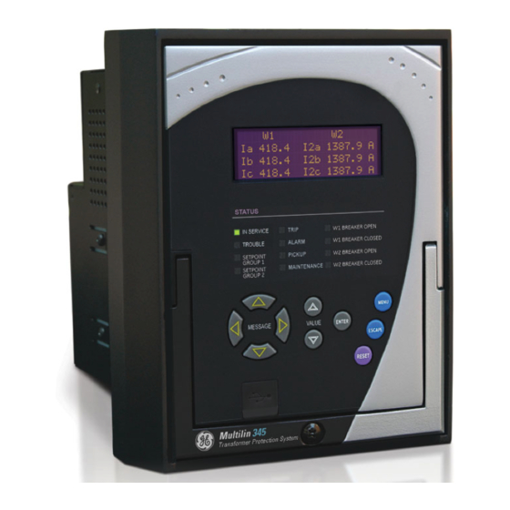
GE Multilin 345 Instruction Manual (254 pages)
Transformer Protection System
Brand:
GE Multilin
| Category:
Other
| Size: 6 MB
Table of Contents
Table of Contents
5
1 Introduction
9
INTRODUCTION Overview
9
Description of the 345 Transformer Protection System
10
Transformer Protection System – Instruction Manual
11
345 Order Codes
15
Specifications
17
Password Security
17
Protection
17
Metering
19
Data Capture
20
Control
20
Monitoring
22
Inputs
22
Outputs
23
Power Supply
23
Communications
24
Testing and Certification
25
Physical
26
Environmental
27
2 Installation
29
Dimensions
29
INSTALLATION Mechanical Installation
29
Product Identification
31
Mounting
32
Standard Panel Mount
32
Drawout Unit Withdrawal and Insertion
37
IP20 Cover (Optional)
38
Electrical Installation
39
Typical Wiring Diagrams
40
345 Terminal Identification
42
Wire Range
45
RMIO Module Installation
46
Phase Sequence and Transformer Polarity
47
Current Inputs
47
Ground and Sensitive Ground CT Inputs
48
Zero Sequence CT Installation
49
Control Power
49
Contact Inputs
50
Trip1 and Trip2 Output Relays
51
Serial Communications
53
Irig-B
54
3 Interfaces
55
INTERFACES Front Control Panel Interface
56
Description
57
Display
58
Working with the Keypad
58
LED Status Indicators - Front Panel with Non-Programmable Leds
59
LED Status Indicators - Front Panel with Programmable Leds
61
Relay Messages
62
Target Messages
62
Self-Test Errors
63
Flash Messages
65
Software Setup
66
Quick Setup - Software Interface
66
Enervista 3 Series Setup Software
66
Hardware and Software Requirements
67
Installing the Enervista 3 Series Setup Software
67
Upgrading the Software
70
Connecting Enervista 3 Series Setup to the Relay
70
Configuring Serial Communications
70
Using the Quick Connect Feature
71
Configuring Ethernet Communications
73
Connecting to the Relay
74
Working with Setpoints and Setpoint Files
75
Engaging a Device
75
Entering Setpoints
75
Setting Programmable Leds
76
File Support
77
Using Setpoint Files
77
Downloading and Saving Setpoint Files
78
Adding Setpoint Files to the Environment
78
Creating a New Setpoint File
79
Upgrading Setpoint Files to a New Revision
79
Printing Setpoints and Actual Values
80
Printing Actual Values from a Connected Device
81
Loading Setpoints from a File
82
Uninstalling Files and Clearing Data
82
Upgrading Relay Firmware
83
Loading New Relay Firmware
83
Advanced Enervista 3 Series Setup Features
85
Transient Recorder (Waveform Capture)
85
Protection Summary
88
Password Security
90
4 Actual Values
93
A1 Status
94
Clock
94
Contact Inputs
94
Output Relays
94
Logic Elements
95
Virtual Inputs
95
Remote Inputs
95
Remote Outputs
95
Contact Inputs Summary
96
Output Relays Summary
96
Logic Elements Summary
96
GOOSE Status
97
GOOSE HDR Status
97
61850 Status
97
A2 Metering
98
Winding 1 Current
98
Winding 2 Current
98
Transformer Differential and Restraint Currents
99
Transformer Thermal Capacity
100
Current Demand 1(2)
100
Clear Current Demand 1 (2)
101
A3 Records
102
Event Records
102
Transient Records
104
Fault Report
105
Learned Data
106
Clear Learned Data
106
Clear Event Record
106
Clear Transient Record
106
Clear Thermal Capacity Record
107
Clear Fault Report
107
A4 Target Messages
108
5 Quick Setup - Front Control Panel
111
6 SETPOINTS Setpoints Main Menu
117
Setpoint Entry Methods
118
Common Setpoints
118
Logic Diagrams
119
Setting Text Abbreviations
120
S1 Relay Setup
121
Clock
121
Password Security
123
Access Passwords
124
Communications
126
RS485 Interface
126
Ethernet
126
Modbus
127
IEC 60870-5-103 Serial Communication
128
IEC60870-5-104 Protocol
128
DNP Communication
128
Series IEC 61850 GOOSE Details
129
Event Recorder
130
Transient Recorder
131
Fault Report
132
Front Panel with Non-Programmable Leds
133
Front Panel with Programmable Leds
134
Installation
136
S2 System Setup
137
Current Sensing
137
Power System
138
Transformer
138
Transformer Setup Phase & Magnitude Compensations
139
Winding Breakers
151
S3 Protection
153
Breaker Tripping
153
Transformer Percent Differential (87T)
156
Transformer Instantaneous Differential (50/87)
161
Restricted Ground Fault (87G or RGF)
163
Thermal Overload (49)
168
Time Overcurrent Curves
172
Phase Timed Overcurrent (51P)
176
Phase Instantaneous Overcurrent (50P)
179
Ground Timed Overcurrent (51G/SG)
181
Ground Instantaneous Overcurrent (50G/SG)
184
Neutral Timed Overcurrent (51N)
187
Neutral Instantaneous Overcurrent (50N)
190
Negative Sequence Timed Overcurrent (51_2)
192
Negative Sequence Instantaneous Overcurrent (50_2)
195
S4 Controls
197
Change Setpoint Group
197
Virtual Inputs
198
Logic Elements
199
Winding Breaker Failure
208
Lockout (86)
210
S5 Inputs/Outputs
212
Contact Inputs
212
Output Relays
213
Output Relay 1 - W1 Breaker "Trip"
214
Auxiliary Output Relays 3 to 6
216
Virtual Inputs
217
Remote Inputs
218
Remote Outputs
218
S6 Monitoring
219
Demand
219
Current Demand
220
RTD Temperature Monitoring (49T)
221
7 Maintenance
227
M3 Breaker Maintenance
230
Trip Coil
230
Breaker Trip Counter
234
Breaker Health
236
Reset Counters
239
M4 Breaker Monitor
240
M5 Relay Maintenance
241
Ambient Temperature
241
M7 Testing
243
Force Leds
243
Force Output Relays
244
General Maintenance
245
In-Service Maintenance
245
Out-Of-Service Maintenance
245
Unscheduled Maintenance (System Interruption)
245
Appendix
247
Repairs
248
Change Notes
249
Manual Revision History
249
Advertisement
Advertisement
Related Products
GE Multilin 565
GE Multilin 575
GE Multilin Categories
Protection Device
Test Equipment
Control Unit
Power distribution unit
Microphone system
More GE Multilin Manuals
Login
Sign In
OR
Sign in with Facebook
Sign in with Google
Upload manual
Upload from disk
Upload from URL