Sign In
Upload
Manuals
Brands
Atest Gaz Manuals
Control Unit
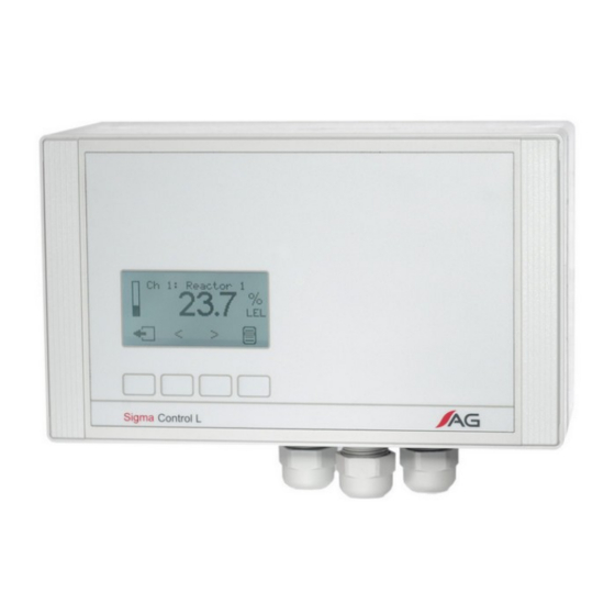
Sigma Control L
Atest Gaz Sigma Control L Manuals
Manuals and User Guides for Atest Gaz Sigma Control L. We have
2
Atest Gaz Sigma Control L manuals available for free PDF download: User Manual
Atest Gaz Sigma Control L User Manual (60 pages)
Brand:
Atest Gaz
| Category:
Control Unit
| Size: 1 MB
Table of Contents
Table of Contents
4
Device Characteristics
6
Preliminary Information
6
Purpose
6
Safety
6
Operation Description
7
Design Description
8
Figure 1: the Construction of the Device and Its Dimensions
8
Figure 2: the Construction of the Device - View with Front Panel Removed
8
Input-Output Interfaces
9
Figure 3: Terminal Block
9
Relay Output Fault
10
Table 1: Terminal Strip Description
10
Table 2: Sigma Control L Unit Default Configuration
10
Figure 4: Fault Relay Contact Status
10
Figure 5: R1 - R3 Relays in Enabled and Disabled Status
11
All-Purpose Relay Outputs (R1 - R3)
11
Digital Inputs DI
12
Visual and Acoustic Indicator Outputs
12
Table 3: Relay Output Operation Programs
12
Figure 6: Principle of Operation the Indicator's Relay Outputs
12
Figure 7: Operation Principle for Visual Indicator Output with Sustained
13
Figure 8: Impulse Valve Control and the Operation Principle for an Acoustic Indicator Output
13
NC Valve Output
14
Service Interface
14
Extension Module Interface
14
Figure 9: NC Valve Control
14
User's Interface
15
Figure 10: Installing the Extension Module
15
Figure 11: Sigma Control L Unit Front Panel with Fields Description
16
Front Panel
16
Table 4: Description of System Visual Indicator Led's
16
Table 5: Description of System Status Led's
17
Figure 12: Push Button and Its Function
17
Interface Structure
18
Access to Options - Log on Mechanism
18
Figure 13: Interface Structure
18
Starting the Unit, Testing the User's Interface
19
System View
19
Figure 14: Welcome Screen
19
Figure 15: System View Screen - System with up to 10 Detectors
20
Figure 16: System View Screen - System with 10 to 20 Detectors
20
Figure 17: System View Screen - NC Valve Control
20
Figure 18: Detector Panel with 10 to 20 Detectors
21
Table 7: Indicator Activation Status
21
Table 6: Collective Text System Description
21
Table 8: Detector Statuses
22
Figure 19: Detector Panel with up to 10 Detectors
22
Detailed Detector View
23
Table 9: Push Button Functions
23
Figure 20: Screen Showing Detailed Detector View
23
Control Unit Detailed View
24
Table 10: Text Description of the Detector Status
24
Table 11: Control Unit Status Text Description
24
Figure 21: Screen with Control Unit Detailed View
24
Detector Menu
25
Control Unit Menu
26
Table 12: Detector Menu
26
Figure 22: Screen During Output Test
26
Table 13: Control Unit Menu
27
Events History
27
Buzzer - Internal Acoustic Indicator
28
Options for SCL Connection in a Gas Detection System
29
Figure 23: Internal Buzzer Operation - Time Diagram
29
Figure 24: a Connection Example: Power Supply 230 V AC and 24 V DC Indicators
29
Figure 25: a Connection Example: One-Colour SOLED3 Signaller
30
Figure 26: a Connection Example: Bi-Colour 24 V DC Indicator to Relay's Outputs
30
Figure 27: a Connection Example: Bi-Colour SOLED3 Signaller to Relay's Outputs
31
Figure 28: a Connection Example: Power Supply 24 V DC and 24 V DC Indicators
31
Figure 29: a Connection Example: Power Supply 230 V AC, 230 V AC Indicators and Valve
32
Figure 30: a Connection Example: Bi-Colour 230 V AC Indicator to Relays Outputs
32
Selecting Cooperation Devices
33
Installation
34
Transport
34
Life Cycle
34
Start up
35
Load Test
35
Periodical Operations
35
Figure 31: Example Connection of Cables to the Device
35
Utilization
36
Troubleshooting
36
Clock Not Set
36
Technical Specifications
37
List of Consumables
38
Product Marking
38
Appendices
38
Table 14: Technical Specification
38
Table 15: List of Consumables
38
Table 16: Method of Product's Marking
38
Extension Module Pca-062A-E2 Gtw Port (Rs-485, Isolated)
40
Design Description
41
Input/Output Interfaces
41
Life Cycle
42
Line Terminator Configuration
42
Module Assembly - Installation
42
Module Configuration
42
Transportation
42
User Interface
42
Detectors Statuses
43
Memory Map for Sigma Control L Unit
43
Memory Maps
43
Transmission Parameter Configuration
43
Output Status and DI1 - DI2 Input Status (Read Only)
44
Extension Module Pws-050 - Visualization Panel / Modbus TCP Gateway
48
Visualization Panel
49
Design Description
50
Input/Output Interfaces
50
User Interface
50
Life Cycle
51
Module Assembly - Installation
51
Module Configuration
51
Transportation
51
Detectors Statuses
52
Memory Map for Sigma Control L Unit
52
Memory Maps
52
Troubleshooting
52
Outputs Status and DI1 - DI2 Inputs Status (Read Only)
53
Control Unit Status (Read Only)
54
Detector Measurement Head Temperature (Read Only)
54
External Digital Inputs (Read / Write)
54
Interface for Executing Operator Commands (Read / Write)
55
Technical Specification
56
Utilization
56
Advertisement
Atest Gaz Sigma Control L User Manual (52 pages)
Brand:
Atest Gaz
| Category:
Control Unit
| Size: 2 MB
Table of Contents
Table of Contents
4
Preliminary Informa!On
6
Safety
6
Purpose
6
Device Characteris Cs
6
Opera!On Descrip!On
7
Figure 1: the Construc!On of the Device and Its Dimensions
8
Figure 2: the Construc!On of the Device - View with Front Panel Removed
8
Design Descrip!On
8
Table 1: Terminal Strip Descrip!On
9
Figure 3: Terminal Strip
9
Input-Output Interfaces
9
Figure 4: Fault Relay Contact Status
10
Table 2: Sigma Control L Unit Default Configura!On
10
Relay Output Fault
10
Figure 5: PK1 - PK3 Relays in Enabled and Disabled Status
11
All-Purpose Relay Outputs (PK1 - PK3)
11
Table 3: Relay Output Opera!On Programs
12
Figure 6: Principle of Opera!On the Indicator's Relay Outputs
12
Digital Inputs DI
12
Visual and Acous C Indicator Outputs
12
Figure 7: Opera!On Principle for Visual Indicator Output with Sustained
13
Figure 8: Valve Control and the Opera!On Principle for an Acous!C Indicator Output
13
Figure 9: Installing the Extension Module
14
Service Interface
14
Extension Module Interface
14
Figure 10: Sigma Control L Unit Front Panel with Fields Descrip!On
15
User's Interface
15
Front Panel
15
Table 4: Descrip!On of System Visual Indicator Led's
16
Table 5: Descrip!On of System Status Led's
16
Figure 11: Push Bu:on and Its Func!On
16
Figure 12: Interface Structure
17
Interface Structure
17
Access to Op Ons - Log on Mechanism
17
Figure 13: Welcome Screen
18
Star Ng the Unit, Tes Ng the User's Interface
18
System View
18
Figure 15: System View Screen - System with 10 to 20 Detectors
19
Figure 14: System View Screen - System with up to 10 Detectors
19
Table 6: Collec!Ve Text System Descrip!On
19
Table 7: Indicator Ac!Va!On Status
20
Figure 16: Detector Panel with 10 to 20 Detectors
20
Figure 17: Detector Panel with up to 10 Detectors
20
Table 8: Detector Statuses
21
Table 9: Push Bu:on Func!Ons
21
Figure 18: Screen Showing Detailed Detector View
22
Detailed Detector View
22
Figure 19: Screen with Control Unit Detailed View
23
Table 10: Text Descrip!On of the Detector Status
23
Table 11: Control Unit Status Text Descrip!On
23
Control Unit Detailed View
23
Detector Menu
23
Table 12: Detector Menu
24
Figure 20: Screen During Output Test
25
Control Unit Menu
25
Table 13: Control Unit Menu
26
Events History
26
Buzzer - Internal Acous C Indicator
26
Figure 21: Internal Buzzer Opera!On - !Me Diagram
27
Op!Ons for SCL Connec!On in a Gas Detec!On System
28
Figure 22: a Connec!On Example: Power Supply 230 V AC and 24 V DC Indicators
28
Figure 23: a Connec!On Example: One-Colour SOLED3 Signaller
28
Figure 24: a Connec!On Example: Bi-Colour 24 V DC Indicator to Relay's Outputs
29
Figure 25: a Connec!On Example: Bi-Colour SOLED3 Signaller to Relay's Outputs
29
Figure 26: a Connec!On Example: Power Supply 24 V DC and 24 V DC Indicators
30
Figure 27: a Connec!On Example: Power Supply 230 V AC, 230 V AC Indicators
30
Selec!Ng Coopera!On Devices
31
Figure 28: a Connec!On Example: Bi-Colour 230 V AC Indicator to Relays Outputs
31
Table 14: Current Consump!On by Connected Detectors
32
Life Cycle
33
Transport
33
Installa on
33
Figure 29: Example Connec!On of Cables to the Device
34
Load Test
34
Start up
34
Periodical Opera Ons
35
U Liza on
35
Troubleshoo!Ng
35
Clock Not Set
35
Technical Specifica!Ons
36
Table 15: Technical Specifica!On
37
Table 16: List of Consumables
37
Table 17: Method of Product's Marking
37
Appendices
37
Product Marking
37
List of Consumables
37
Extension Module Pca-062A-E2 Port Gtw (Rs-485, Isolated)
39
Design Description
40
Input/Output Interfaces
40
Life Cycle
41
Module Assembly - Installation
41
Module Configuration
41
Transportation
41
User's Interface
41
Memory Map for Sigma Control L Unit
42
Memory Maps
42
Utilization
45
Technical Specifications
46
Connection Cable
47
Advertisement
Related Products
Atest Gaz Sigma MOD DRV
Atest Gaz Sigma MOD AO
Atest Gaz Sigma MOD LED
Atest Gaz Sigma MOD DO
Atest Gaz Sigma SmArt
Atest Gaz Alpa MOD LED1
Atest Gaz Alpa MOD LED8
Atest Gaz EcoAlpa PW-054 Series
Atest Gaz EcoAlpa PW-054-LED2-1212
Atest Gaz EcoAlpa PW-054-LED2-230
Atest Gaz Categories
Control Unit
Gas Detectors
Security Sensors
Controller
More Atest Gaz Manuals
Login
Sign In
OR
Sign in with Facebook
Sign in with Google
Upload manual
Upload from disk
Upload from URL