
Related Manuals for Marmitek TWM4


Summary of Contents for Marmitek TWM4
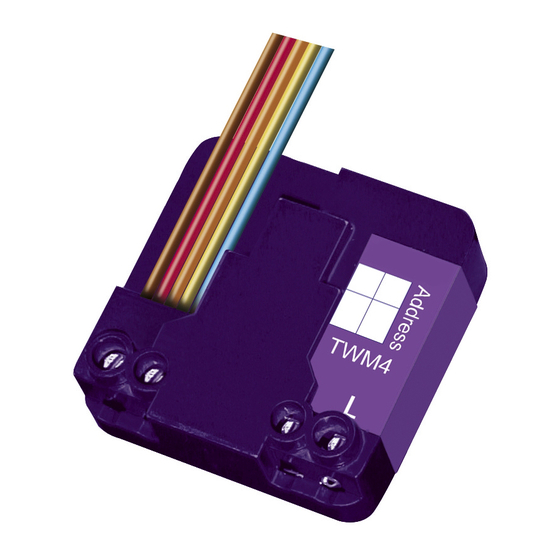
- Page 1 TWM4 ™ MICRO MODULE TRANSMITTER 20246/20080220 • TWM4™ Micro module transmitter ALL RIGHTS RESERVED MARMITEK ©...
- Page 2 © MARMITEK...
-
Page 3: Table Of Contents
• In case of improper usage or if you have altered and repaired the product yourself, all guarantees expire. Marmitek does not accept responsibility in the case of improper usage of the product or when the product is used for purposes other than specified. -
Page 4: How Does Marmitek X-10 Work
1. When several phases are used in the house, it can be necessary to couple these phases for Marmitek X-10 signals. You can couple them with the use of a CAT 3000 active 3 phase coupler/repeater (Art.No. 09304) and it is required... - Page 5 However, it is possible that the Marmitek X-10 signals are disturbed by e.g. baby phones which are in TALK mode (continuous transmission). When these kind of signals are present on the power line it is possible that the Marmitek X-10 signals will not come through.
-
Page 6: Introduction
(rocker) switches or Momentary switches. Suitable for controlling various Marmitek modules (actuators) through X-10 commands. The TWM4 can also be used behind a (rocker) switch or Momentary switch to start programming macros in, for example, a Marmitek CM15Pro Computer Interface. -
Page 7: Connection Applications
Please see the programming chapter for the colour coding. Please note: The blue input wire of the TWM4 is connected internally to the neutral terminal. Make sure that the phase and neutral connections are correctly connected to the module. If phase and neutral are swapped, there will be 230 V on the input wires of the module. - Page 8 Blue (N) Red (2) Orange (3) Yellow (4) Blue PROG. TWM4 Brown Brown (1) Figure 2. • Connect the phase wire (L) to the L connection of the module and the neutral wire (N) to one of the neutral connections (N).
- Page 9 Blue (N) PROG. TWM4 Brown (1) Figure 3. • Position the module with the back against the rear of the back box, behind the wiring. • If the module has not yet been programmed or has been incorrectly programmed, then it can now be programmed.
-
Page 10: Programming
6. Test the operation of all the inputs. Please note: If, immediately after putting the module in Programming mode, an address is sent twice, the module will return to the default value for function and options (On/Off switch commands)! © MARMITEK... - Page 11 Send the set-up command (letter and figure code) that belongs to the desired address twice via the power line using a programming unit (PRU256) or another X-10-compatible transmitter (e.g. a Marmitek remote control). The LED will flash twice after two identical set-up commands (addresses) have been received.
- Page 12 4. Programming options The TWM4 has the option of converting the internal status (from ON to OFF or from OFF to ON) upon receiving a group command: All Lights On, All Lights Off, All Units Off.
- Page 13 When the switch of the TWM4 is pressed afterwards, the module would normally give an OFF command. However, if the actuator is switched off by an All Units Off group command, the TWM4 must change its internal status accordingly, so that an ON command is sent when the button is next pressed.
- Page 14 If the status of the module has to change with group commands All Lights On and All Units Off. Action No. of LED flashes Send All Lights On (2 x) Send All Units Off (2 x) Result • ON/OFF function available for all inputs. • Other inputs are automatically given consecutive addresses.. © MARMITEK...
- Page 15 Send set-up command for any options (2 x) All Lights ON, All Lights OFF, All Units OFF Example of programming on address B03 Action No. of LED flashes Send address B03 (2 x) Send set-up command BRIGHT (2 x) TWM4™...
- Page 16 Long pulse (> 0.5 s) DIM or BRIGHT • Depends on the status of the switch actuator or address to be controlled (toggle mode). 3.3 Sending dimming commands with Momentary switches with two normally open contacts Brown Blue © MARMITEK...
- Page 17 Short pulse (< 0,5 s) OFF, long pulse (> 0,5 s) DIM Orange ON/BRIGHT Short pulse (< 0,5 s) ON, long pulse (> 0,5 s) BRIGHT Yellow OFF/DIM Short pulse (< 0,5 s) OFF, long pulse (> 0,5 s) DIM TWM4™...
- Page 18 All Units Off Sends All Units Off using letter code B when switch is pressed Orange All Lights Off Sends All Lights Off using letter code B when switch is pressed Yellow Sends OFF command when switch is pressed © MARMITEK...
-
Page 19: Frequently Asked Questions
E. Start with the MicroModule in setup mode. • Press the Marmitek X10 button (marked with the symbol of a house) of the 8-in-1 remote control and then press button 3. • Press the “ON” button 2x (= channel+). -
Page 20: Technical Data
Tip: do not press the keys too fast, so the transmitter gets enough time to send the signals to the mains. Do you still have questions? Please check out www.marmitek.com for more information. TECHNICAL DATA... -
Page 21: Declaration Of Conformity
2003 on the restriction of the use of certain hazardous substances in electrical and electronic equipment Bij deze verklaart Marmitek BV, dat deze TWM4 voldoet aan de essentiële eisen en aan de overige relevante bepalingen van Richtlijnen: RICHTLIJN 2004/108/EG VAN HET EUROPEES PARLEMENT EN DE RAAD van 15...
Need help?
Do you have a question about the TWM4 and is the answer not in the manual?
Questions and answers