Table of Contents
Advertisement
Advertisement
Table of Contents

Related Manuals for StandDesk PRO


Summary of Contents for StandDesk PRO
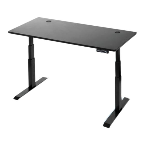
- Page 1 2017 XO-58-PB02 Dual Motor Triple Segment Frame...
- Page 2 USE / LIABILITY This StandDesk is height adjustable so that it can be positioned at the most ergonomically suitable height. Any other use is at your risk. Under no circumstances does StandDesk accept warranty claims or liability claims...
- Page 3 WATCH ASSEMBLY VIDEO www.standdesk.co/pages/faq CLICK ON StandDesk Pro Assembly HIGHLY RECOMMENDED...
- Page 4 If you have the stickers, make sure their color and number match up, like so. PERFECT MATCH Your desk might not have the sticker system to match up and align parts. But not to worry, the assembly process is just the same.
- Page 5 TOOLS REQUIRED TOOLS Phillips Head Screwdriver 4mm Hex Bit (Optional) Power Drill (Optional) Tape Measure COMPONENTS Legs Support Braces (x2) Middle Slats Feet (x2) Stabilizing Foot Plates (x2) Control Box Holder Control Box Standard Handset OPTIONAL UPGRADES Memory Handset Power Cords (x3) Cable Management Tray Crossbar (REPLACES STANDARD HANDSET IF ORDERED)
- Page 6 Component Name Component Name Legs M6 x 12 Bolts Support Braces Inserts Middle Slat Washers Feet ST 3.5 x 16 Screws ST 4.8 x 16 Screws Stabilizing Foot Plates Control Box Holder M6 x 12 Anti-slip Bolts Control Box M6 x 25 Anti-slip Bolts Standard Handset M6 x 35 Anti-slip Bolts Power Cords...
- Page 7 Crossbar plates facing BACK BACK STEP 1 PRO TIP If you’re using a StandDesk top, place the support braces on the desk so they line up with the pre-drilled holes. It’ll make it easier for you later on.
- Page 8 Attach a support brace to each leg using four M6x12 anti-slip bolts. Ensure the flat side is touching the desktop. Match up the triangles so they kiss STEP 2 Find the middle slat. Loosen but don’t remove the pre-installed bolts. Adjust the width of the slat by pulling each end away from each other.
- Page 9 Line up the holes on the middle slat to the holes on the legs. Attach the middle slat using eight M6x35 anti-slip bolts. STEP 4 Place the stabilizing foot plates on each leg. STEP 5...
- Page 10 Place the feet on top of the stabilizing foot plates and align the holes. Finger tighten four M6x12 anti-slip bolts in a diagonal pattern for best fit. Once all bolts are aligned, fully screw them STEP 6 If you purchased the optional cable management tray, attach it face down to the back middle slat using four M6x12 bolts and washers.
- Page 11 If you purchased the optional crossbar, loosen but don’t remove the pre-installed bolts in the middle. Then, adjust the width. STEP 8 OPTIONAL UPGRADE Ensure that the raised bolt holes are facing out. Attach the crossbar to the holes on the back of the legs using four M6x25 anti-slip bolts.
- Page 12 Secure the control box to the control box holder using two inserts, pressing them down firmly. STEP 10 Attach the control box holder to the front middle slat using two M6x12 anti-slip bolts. FRONT MIDDLE SLAT STEP 11...
- Page 13 Attach the frame to the top using six ST 4.8x16 screws. STEP 12 PRO TIP If your top does not have pre-drilled holes, you can use a drill or a power tool to attach your top. Here’s a separate video to help you out.
- Page 14 Attach the handset to the top using two ST 3.5x16 screws. STEP 13 Connect the handset cord and the two extension cords to the front side of the control box. Connect the power cord to the back. Almost there! FRONT BACK STEP 14...
- Page 15 Finally, use the two extension cords to connect each leg motor to the control box. STEP 15 Be sure to tighten all the bolts. Carefully flip the desk over onto the feet. Flip the desk over by raising the front side up first, so you don’t damage the handset.
- Page 16 Yay!!! Congratulations! Time to plug it in! Be sure there are no obstacles in the way for when the desk moves up and down. STEP 17 Finally, it’s time to turn the desk on by holding the down button until it reaches the lowest position. If you have a memory handset, it will say for SUCCESS.
- Page 17 You’re done! Time to celebrate - here’s to standing for your health, happiness and productivity! F I N I S H Setting 1 Setting 2 Setting 3 Menu LED Display Up Arrow Down Arrow...
- Page 18 WAKE UP: Press any button! CALIBRATE OR RESET: Press and hold for 15 seconds. Led display shows Hold until display shows . Release; the display shows 24”. Stands for go to lowest position to tell you that your desk must be re-set. See above. GLP: Stands for connection if one of the frame legs is not working properly.
- Page 19 SEATING STORAGE ERGONOMICS...
- Page 20 OFF ALL ACCESSORIES PROMO CODE To learn more about our products, visit our website at www.standdesk.co facebook.com/thestanddesk instagram.com/thestanddesk twitter.com/thestanddesk...
Need help?
Do you have a question about the PRO and is the answer not in the manual?
Questions and answers