Advertisement
Quick Links
Advertisement

Related Manuals for StandDesk Ergo Tech STANDING DESK


Summary of Contents for StandDesk Ergo Tech STANDING DESK
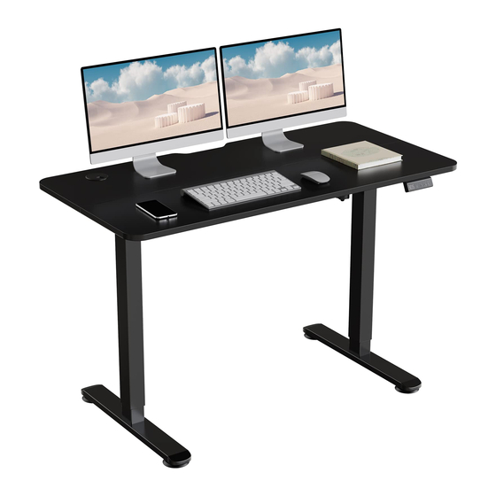
- Page 1 STANDING DESK Installation Instructions 800 524 2744 PAGE 1 OF 17 P516373 REV B...
- Page 2 IMPORTANT SAFETY INSTRUCTIONS CONSIGNES DE SECURITE IMPORTANTES SAVE THESE INSTRUCTIONS VEUILLEZ GARDER CES CONSIGNES When using an electrical furnishing, basic precautions should always be followed, Lorsque vous utilisez des meubles electriques, des precautions de base doivent toujours including the following: etre respectees, y compris les suivantes.
- Page 3 STANDING DESK Parts List Primary Leg Center Lid Glider Switch Black = 65020610-1 Black = R033 41610 RM-175 R013345-2 White = 65020604-1 White = R033 41604 Silver = 65020630-1 Silver = R033 41630 Secondary Leg Feet Velcro Strip Power Cable 3.5m Black = 65020610-2 Black = R063 39110 R010250...
- Page 4 PLACE PRIMARY AND SECONDARY LEGS Place the Primary and Secondary Legs (Part A & Part B) on the bottom of your worksurface. Secondary Leg Primary Leg connection view connection view (1x) (1x) 800 524 2744 PAGE 4 OF 17...
- Page 5 PLACE & ALIGN SIDE BRACKETS Place and align Side Brackets (Part C) onto the worksurface. (2x) Image shown with 60" x 30" surface Image shown with 48" x 30" surface 800 524 2744 PAGE 5 OF 17...
- Page 6 PLACE & ALIGN SIDE BARS Place and align the Side Bars (Part D) onto the Legs using the hinges and slots. (2x) 800 524 2744 PAGE 6 OF 17...
- Page 7 PLACE & ALIGN CENTER BRACKETS Place and align Center Brackets (Part E) on top of the Side Brackets (Part C) to connect them. (2x) Image shown with 60" x 30" surface Image shown with 48" x 30" surface 800 524 2744 PAGE 7 OF 17...
- Page 8 IF WORKSURFACE HAS PREDRILLED PILOT HOLES SKIP TO NEXT STEP FRAME ALIGNMENT DIAGRAM Rectangular: (45in, 48in - 72in) Long x (24in, 26in, 27in, 30in) Wide PILOT HOLES Mark pilot hole locations Recommended drill bit size for pre-drilling pilot holes: 1/8" (3mm) diameter wood drill bit ø...
- Page 9 WOOD SCREW ATTACHMENT Install the components placed on the worksurface from the previous steps to the worksurface using 26 wood screws (Part H). (26x) Image shown with 60" x 30" surface 800 524 2744 PAGE 9 OF 17...
- Page 10 INSTALL FEET AND GLIDERS Place Feet (Part G) on top of Legs so that the Leg fits into the top side of the Feet. (4x) (2x) Secure Feet to Leg using 4 bolts (Part J) and supplied Allen wrench (Part T). Screw in Gliders (Part K) to be hand tight.
- Page 11 INSTALL SWITCH MOUNT & SWITCH Align the Switch Bracket (Part N) with the two predrilled holes near the edge of the worksurface. Install the Switch Bracket using 2 wood screws (Part I) (2x) to secure the Switch Bracket to the worksurface. Once bracket is mounted, slide the Switch (Part P) on the bracket, firmly push it down towards the worksurface until it’s secure.
- Page 12 PLUG IN POWER & SWITCH COMPONENTS Begin by plugging the Switch (Part P) into the Secondary Leg. Plug Motor Cable (Part S) into the Primary Leg. Plug DC Cable (Part R) into the Secondary Leg Actuator and the Power Supply (Part O). Use the Velcro Strips (Part L) to secure and manage cords neatly if desired.
- Page 13 INSTALL CENTER LID Place the Center Lid (Part F) on top of the Center Brackets (Part D) and push down firmly until it clicks or snaps into place. To remove the tray, pull up on the Center Tray Cover until it pops off. 800 524 2744 PAGE 13 OF 17...
- Page 14 FLIP THE STANDING DESK UPRIGHT We recommend using two people to safely flip the completed standing desk onto its feet. Check to ensure the power cord reaches a power source. If not, remove Center Lid (Part F), pull more power cord out and re-install Center Lid.
- Page 15 PERFORM INITIAL RESET DIGITAL SWITCH OPERATION ADJUSTING INITIAL HEIGHT Connect power cord to 120v power outlet. It may be necessary to adjust the displayed height due to different thicknesses of desktops etc. The DPF1C will as INITIALIZE standard either show 68 cm or 24.5 inch as the default The desk cannot drive up if it has not been initialized.
-
Page 16: Trouble Shooting And Diagnosis
TROUBLE SHOOTING AND DIAGNOSIS 800 524 2744 FORCE REQUIRED TO ACTIVATE ANTI-COLLISION STANDARD ERROR CODES The included electric height adjustable table that is not working properly can be evaluated to determine why the Upwards: 44 lbs (20 kg) table isn’t functioning. Downwards: 88 lbs (40 kg + load on desk and desk itself) ERROR DESCRIPTION... -
Page 17: Specifications
SPECIFICATIONS BASE • Complete 2-leg, 3-stage, electric light, adjustable frame • 700mm (27.56") T-foot, centered, entry level construction • 500mm (19.69") under-frame • Flex Frame, three-piece, adjustable construction • Complete frame outside dimension, adjustment range: 44.0" - 70.0" (1168.4mm - 1778.0mm) - Infinitely adjustable within adjustment range •...
Need help?
Do you have a question about the Ergo Tech STANDING DESK and is the answer not in the manual?
Questions and answers