Sign In
Upload
Download
Table of Contents
Contents
Add to my manuals
Delete from my manuals
Share
URL of this page:
HTML Link:
Bookmark this page
Add
Manual will be automatically added to "My Manuals"
Print this page
×
Bookmark added
×
Added to my manuals
Manuals
Brands
Garmin Manuals
Marine Radio
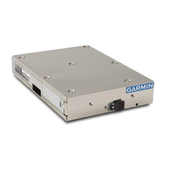
GTX 45R
Installation manual
Garmin GTX 45R Installation Manual
Hide thumbs
1
2
3
4
5
6
7
8
Table Of Contents
9
10
11
12
13
14
15
16
17
18
19
20
21
22
23
24
25
26
27
28
29
30
31
32
33
34
35
36
37
38
39
40
41
42
43
44
45
46
47
48
49
50
51
52
53
54
55
56
57
58
59
60
61
62
63
64
65
66
67
68
69
page
of
69
Go
/
69
Contents
Table of Contents
Bookmarks
Table of Contents
Table of Contents
1 System Overview
Scope
Equipment Description
Definitions and Abbreviations
ADS-B Capabilities
FIS-B Capabilities
TIS-A System Capabilities
Interface Summary
General Specifications
Transponder Specifications
UAT Receiver Specifications (GTX 45R Only)
1090 Mhz Receiver Specifications
Power Specifications
Certification
License Requirements
Reference Documents
2 Limitations
3 Installation Overview
Introduction
Unit Configurations
Accessories Supplied
Optional Accessories
Necessary Installation Materials and Accessories Not Supplied
Necessary Special Tools
Transponder Antenna
Minimum Systems Configuration
GTX Pressure Altitude Input
ADS-B in Considerations (GTX 45R Only)
Bluetooth Considerations (GTX 45R Only)
Antenna Considerations
Electrical Bonding
Cabling and Wiring
Electrical Bonding Considerations
Cooling Requirements and Considerations
4 Installation Procedure
Wire Harness Installation
Backshell Assembly Parts
Shielded Cable Preparation
Connector and Backshell Assembly
Coaxial Cable Installation
GAE Installation (Optional)
Equipment Rack Installation
Unit Installation and Removal
5 Connector Pinout Information
Main Board Connector - P3251
ADS-B Board Connector - P3252 (GTX 45R Only)
Power
Altitude Inputs
Discrete I/O
Serial Data Interfaces
Suppression Bus
Garmin Altitude Encoder
USB Interface
6 Post Installation Configuration and Checkout
System Configuration Overview
Mounting, Wiring, and Power Checks
Configuration Mode and Settings
Unit Configuration and Software (Garmin Dealers Only)
Software Installation Procedure (Garmin Dealers Only)
7 Continued Airworthiness
Appendixa Gtx X5 Mechanical Drawings
Appendixb Equipment Compatibility and Configuration
ADS-B in Displays (GTX 45R Only
GPS Sources
Appendixc Interconnect Drawings
Advertisement
Quick Links
1
Equipment Description
2
Configuration Mode and Settings
Download this manual
GTX 35R/45R Installation Manual
(Non-Certified Aircraft)
190-01499-10
October 2017
Revision 1
Table of
Contents
Previous
Page
Next
Page
1
2
3
4
5
Advertisement
Table of Contents
Need help?
Do you have a question about the GTX 45R and is the answer not in the manual?
Ask a question
Questions and answers
Related Manuals for Garmin GTX 45R
Marine Radio Garmin GTX 330 System Maintenance Manual
With ads-b out system (56 pages)
Marine Radio Garmin GTX 330 Series Manual
Equipment supplement (8 pages)
Marine Radio Garmin GTX 330 Installation Manual
(49 pages)
Marine Radio Garmin GTX 330 Installation Manual
Transponder (77 pages)
Marine Radio Garmin GTX 330 Installation Manual
(73 pages)
Marine Radio Garmin GTX 330D Maintenance Manual
(133 pages)
Marine Radio Garmin GTX 330 Pilot's Manual
Mode s transponder (6 pages)
Marine Radio Garmin 320 Installation Manual
Garmin gtx 320 aviation-transponder: install guide (37 pages)
Marine Radio Garmin GTX 335 Series Pilot's Manual
All-in-one ads-b transponder (36 pages)
Marine Radio Garmin GTX 345 Operator's Manual
Enstrom f-28f/280fx (28 pages)
Marine Radio Garmin GTX 327 Installation Manual
Garmin gtx 327 transponder installation manual (55 pages)
Marine Radio Garmin GTX 327 Pilot's Manual
Mode a/c transponder (9 pages)
Marine Radio Garmin GTX 327 Pilot's Manual
(8 pages)
Marine Radio Garmin GTX 33 Installation Manual
Installation manual (83 pages)
Marine Radio Garmin GTX 325 Installation Manual
Tso (67 pages)
Marine Radio Garmin GTX 335 w GPS Installation Guidance
(116 pages)
This manual is also suitable for:
Gtx 35r
Table of Contents
Save PDF
Print
Rename the bookmark
Delete bookmark?
Delete from my manuals?
Login
Sign In
OR
Sign in with Facebook
Sign in with Google
Upload manual
Upload from disk
Upload from URL


Need help?
Do you have a question about the GTX 45R and is the answer not in the manual?
Questions and answers