Table of Contents
Advertisement
TRANSMISSION IDENTIFICATION .........................................................................................
GENERAL DESCRIPTION ..........................................................................................................
INTERNAL COMPONENT IDENTIFICATION AND LOCATIONS .......................................
SOLENOID APPLICATION CHART ..........................................................................................
FLUID REQUIREMENTS AND CHECKING PROCEDURE ...................................................
OIL LEVEL CONTROL ................................................................................................................
SOLENOID LOCATIONS AND IDENTIFICATION .................................................................
SOLENOID OPERATION ............................................................................................................
ELECTRICAL CONDUCTOR PLATE ........................................................................................
CASE CONNECTOR TERMINAL IDENTIFICATION .............................................................
PARK/NEUTRAL CONTACT AND FLUID TEMP SENSOR ....................................................
N2 AND N3 INPUT SPEED SENSORS .......................................................................................
TRANSMISSION CONTROL MODULE AND LOCATIONS ....................................................
TCM CONNECTORS AND TERMINAL IDENTIFICATION ...................................................
SOLENOID RESISTANCE CHART ............................................................................................
SHIFT LEVER ASSEMBLY .........................................................................................................
TRANSMISSION RANGE RECOGNITION SWITCH ...............................................................
WIRING SCHEMATICS ...............................................................................................................
DIAGNOSTIC TROUBLE CODE DESCRIPTION ....................................................................
TORQUE CONVERTER OPERATION .......................................................................................
CHECKBALL AND SMALL PARTS LOCATIONS ....................................................................
HYDRAULIC PASSAGE IDENTIFICATION .............................................................................
F-1 AND F-2 FREEWHEEL DIRECTIONS ...............................................................................
TRANSMISSION DISASSEMBLY ..............................................................................................
COMPONENT REBUILD
TRANSMISSION CASE ASSEMBLY ..................................................................................
CONVERTER HOUSING, OIL PUMP AND B-1 CLUTCH ASSEMBLY .........................
K-1 CLUTCH HOUSING ASSEMBLY (INCLUDES F-1 SPRAG) ....................................
K-2 CLUTCH HOUSING ASSEMBLY ................................................................................
GEARTRAIN IDENTIFICATION AND POSSIBLE TOOTH COUNTS ...........................
CENTER AND REAR PLANETARY GEARTRAIN ASSEMBLY (INCLUDES F-2) .......
K-3 CLUTCH HOUSING ASSEMBLY ................................................................................
B-2 CLUTCH HOUSING ASSEMBLY ................................................................................
VALVE BODY ASSEMBLY ..................................................................................................
TRANSMISSION FINAL ASSEMBLY ........................................................................................
TORQUE SPECIFICATIONS ......................................................................................................
Note: An "Update Handbook" with the familiar Green cover, is also available from ATSG
and includes much more information on the valve body variations that are found in the
722.6 transmission.
AUTOMATIC TRANSMISSION SERVICE GROUP
INDEX
18635 S.W. 107 AVENUE
CUTLER BAY, FLORIDA 33157
(305) 670-4161
Copyright © ATSG 2009
M E R C E D E S , J A G U AR,
D A I M L ER / C H RY S L E R
" 7 2 2 .6 " "5 S p e e d "
3
7
8
9
10
11
12
13
16
17
18
19
20
22
23
24
26
27
29
34
35
36
38
39
48
49
60
68
79
81
86
96
102
109
120
Advertisement
Table of Contents

Related Manuals for ATSG 722.6


Summary of Contents for ATSG 722.6
-
Page 1: Table Of Contents
VALVE BODY ASSEMBLY ....................TRANSMISSION FINAL ASSEMBLY ..................TORQUE SPECIFICATIONS ...................... Note: An "Update Handbook" with the familiar Green cover, is also available from ATSG and includes much more information on the valve body variations that are found in the 722.6 transmission. - Page 2 "722.6" "5 Speed" The Mercedes 722.6 transmission made its first debut here in the United States in 1996. It is used behind 4, 6, 8 and 12 cylinder gasoline engines, as well as their diesel engines. It is their first completely computer controlled transmission and their first to have a transmission with a converter clutch.
-
Page 3: Transmission Identification
Technical Service Information TRANSMISSION IDENTIFICATION To utilize the 722.6 transmission behind the diesel, and the 4, 6, 8 and 12 cylinder gas engines, different gear ratios and torque capacities are needed. Various ratios are accomplished in 2 ways: 1. Different size axle ratios in the rear differential. - Page 4 Check Digit J=Coupe, K=Cabriolet/Roadster, M=AMG Vehicle Restraint System Model Designation 70=S430, 75=S500 VIN digits 4 through 7 to Chassis Designation Conversion Chart for vehicles equipped with the 722.6 Transmission up to Model Year 2001 Model Year Chassis Engine Transmission C230 1997-1998 202.023...
- Page 5 Check Digit J=Coupe, K=Cabriolet/Roadster, M=AMG Vehicle Restraint System Model Designation 70=S430, 75=S500 VIN digits 4 through 7 to Chassis Designation Conversion Chart for vehicles equipped with the 722.6 Transmission up to Model Year 2001 Model Year Chassis Engine Transmission E55 AMG 1999 210.074...
- Page 6 Technical Service Information mercedes 722.6 usage 2002-2004 SEDANS C240 Sedan - 2.6L, 18 Valve, V-6 Engine. C320 Sedan - 3.2L, 18 Valve, V-6 Engine. C32 AMG Sedan - Supercharged SOHC 3.2L, 18 Valve, V-6 Engine. E320 Sedan - 3.2L, 18 Valve, V-6 Engine.
-
Page 7: General Description
Copyright © 2009 ATSG Figure 5 GENERAL DESCRIPTION The Mercedes 722.6 transmission made its first The TCM commands shift solenoids and variable debut in the United States in 1996. It is used behind 4, bleed Pulse Width Modulated (PWM) solenoids 6, 8 and 12 cylinder gasoline engines, as well as their within the transmission to control shift timing. -
Page 8: Internal Component Identification And Locations
2 Mode Selector Switch in the "W" position. 3 Shift components required for engine braking during coast conditions. * TCC is available in 2nd thru 5th gear, based on throttle position, fluid temp and vehicle speed. Copyright © 2009 ATSG Figure 6 AUTOMATIC TRANSMISSION SERVICE GROUP... -
Page 9: Solenoid Application Chart
Technical Service Information 722.6 TRANSMISSION SOLENOID APPLICATION CHART From the solenoid shift chart below, you will notice that shift solenoids 1-2/4-5, 2-3 and 3-4 are toggled “on-to-off” to make there respective shifts. While in gear they remain in the “off” state. This explains why, while you are driving, whatever the gear the transmission was in at the time the computer system observed a fault, that would be the gear the transmission failsafes to. -
Page 10: Fluid Requirements And Checking Procedure
Grand Cherokee comes equipped with a dipstick.. Approximate measurements taken from the bottom of the stick to the individual fill lines. 2.142” 2.541” 54.4mm 64.5mm 0.413” 0.820” 10.5mm 20.8mm Overall Length = 35 3/4" Copyright © 2009 ATSG Figure 8 AUTOMATIC TRANSMISSION SERVICE GROUP... -
Page 11: Oil Level Control
Figure 9. ATF above the full level. The "Float" prevents expanded or overfilled ATF from reaching the gearset chamber. Copyright © 2009 ATSG Figure 9 AUTOMATIC TRANSMISSION SERVICE GROUP... -
Page 12: Solenoid Locations And Identification
Technical Service Information ELECTRONIC COMPONENTS Solenoid Locations And Identification All models of the 722.6 transmission use a total of six These covers are not available seperately for retro- solenoids mounted on the electronic conductor plate fitting. When a new conductor plate is purchased, and the valve body, as shown in Figure 10. -
Page 13: Solenoid Operation
The SPC and MPC solenoids are interchangeable and work in tandem together to control holding clutch Electronic Components pressure as well as to assist the shift solenoids to Continued on Page 16 control shift feel. Copyright © 2009 ATSG AUTOMATIC TRANSMISSION SERVICE GROUP... - Page 14 Control Valve Overlap Control Overlap Control Valves Via Valves Via The Working Pressure Control Valve The Working Pressure Control Valve Copyright © 2009 ATSG Figure 11 SHIFT PRESSURE CONTROL (SPC) SOLENOID OPERATION "MAXIMUM CLUTCH PRESSURE" "MINIMUM CLUTCH PRESSURE" Mercedes Minimum...
- Page 15 To Lock-up 140 277 04 35 Control Valve Control Valve From Shift Pressure From Shift Pressure Control Valve Control Valve Copyright © 2009 ATSG Figure 13 1-2/4-5, 2-3, AND 3-4 SHIFT SOLENOID OPERATION SOLENOID "OFF” SOLENOID "ON” Exhaust Blocked Open To...
-
Page 16: Electrical Conductor Plate
(Face View) Speed Sensor Park/Neutral Contact MERCEDES-BENZ ATF Temperature 140 270 03 61 Sensor Press fit solenoid contacts. Ensure snug fit solenoid terminals. If loose, close down contact slots carefully. Copyright © 2009 ATSG Figure 15 AUTOMATIC TRANSMISSION SERVICE GROUP... -
Page 17: Case Connector Terminal Identification
2-3 Shift Solenoid Ground Control 3-4 Shift Solenoid Ground Control Shift Pressure Control Solenoid Ground Control TCC Solenoid Ground Control Electrical Conductor Sensor Ground Plate Connector 1-2/4-5 Shift Solenoid Ground Control (Face View) Copyright © 2009 ATSG Figure 16 AUTOMATIC TRANSMISSION SERVICE GROUP... -
Page 18: Park/Neutral Contact And Fluid Temp Sensor
Reverse or Drive, as engine temp Electronic Components is used in Park and Neutral. Continued on Page 19 tft sensor and p/n contact ELECTRICAL CONDUCTOR DRY-REED PLATE CONTACT PERMANENT MAGNET PLUNGER Copyright © 2009 ATSG Figure 17 AUTOMATIC TRANSMISSION SERVICE GROUP... -
Page 19: N2 And N3 Input Speed Sensors
ATF TEMP VOLTAGE RESISTANCE N2 and N3 Input Speed Sensors -40C (-40F) 0.80 564.0 The 722.6 transmission uses 2 input speed sensors -30C (-22F) 0.88 624.0 referred to as N2 and N3. Both speed sensors are -20C (-4F) 0.95 686.0... -
Page 20: Transmission Control Module And Locations
Technical Service Information ELECTRONIC COMPONENTS (CONT'D) Transmission Control Module (TCM) The 722.6 electronic operated transmission is Permanent "Limp-In" DTC will recover when the controlled by a Transmission Control Module (TCM) key is cycled, but if the same DTC is detected for three and has a fully adaptive control system. - Page 21 Chrysler 300C; TCM mounted below the steering column in position "A" Grand Cherokee; TCM mounted below the steering column in position "A" Copyright © 2009 ATSG Figure 21 ELECTRICAL AND RESISTANCE CHECKS Electrical and resistance checks can be easily as the...
-
Page 22: Tcm Connectors And Terminal Identification
Modulation Pressure Control (MPC) Solenoid Ground Signal Shift Pressure Control (SPC) Solenoid Ground Signal Battery Voltage Supply to All Solenoids CAN Bus Data Line Low (-) CAN Bus Data Line High (+) Copyright © 2009 ATSG Figure 22 AUTOMATIC TRANSMISSION SERVICE GROUP... -
Page 23: Solenoid Resistance Chart
2-3 Shift Solenoid Ground Control 3-4 Shift Solenoid Ground Control Shift Pressure Control Solenoid Ground Control TCC Solenoid Ground Control Electrical Conductor Sensor Ground Plate Connector 1-2/4-5 Shift Solenoid Ground Control (Face View) Copyright © 2009 ATSG Figure 23 AUTOMATIC TRANSMISSION SERVICE GROUP... -
Page 24: Shift Lever Assembly
DRIVER SHIFT CONTROL SHIFT LEVER ASSEMBLY W/S Mode W/S Mode Selector Selector Switch Switch Copyright © 2009 ATSG Copyright © 2009 ATSG Figure 24 Figure 25 SHIFT LEVER ASSEMBLY Standard Shift Lever Assembly The transmission Shift Lever Assemblies vary by model. - Page 25 - Park position enables the engine to be started while preventing the vehicle from moving. For safety reasons, the vehicle's parking brake should always be used in addition to the "Park" position. Copyright © 2009 ATSG AUTOMATIC TRANSMISSION SERVICE GROUP...
-
Page 26: Transmission Range Recognition Switch
Measured with the TCM connector unplugged TRRS and the ignition in the “ON” position. TRRS TCM Power Note: This test applies only to 1996-1999 models. 2000-Up models require the proper scanner. TCM Ground Copyright © 2009 ATSG Figure 26 AUTOMATIC TRANSMISSION SERVICE GROUP... -
Page 27: Wiring Schematics
C2 Conn Solenoid (See Page 21 For Locations) Twisted TCC (PWM) Pair Solenoid COMPUTER 2-3 Shift Solenoid DATA LINE SYSTEM Note: Wire Colors Vary 3-4 Shift Solenoid 1-2/4-5 Shift Solenoid Copyright © 2009 ATSG Figure 27 AUTOMATIC TRANSMISSION SERVICE GROUP... - Page 28 Modulation Pressure C2 Conn Solenoid Twisted TCC (PWM) Pair Solenoid Note: Wire Colors Vary 2-3 Shift TO SHIFT Solenoid LEVER ASM AND OTHER MODULES 3-4 Shift Solenoid 1-2/4-5 Shift Solenoid Copyright © 2009 ATSG Figure 28 AUTOMATIC TRANSMISSION SERVICE GROUP...
-
Page 29: Diagnostic Trouble Code Description
An X in this column means that it's a code that will automatically be eliminated, after fault condition ends. "Key Reset" Column An X in this column means that it is a code that can be eliminated by cycling the ignition key OFF to ON. Copyright © 2009 ATSG AUTOMATIC TRANSMISSION SERVICE GROUP... - Page 30 P0700 Transfer Case Control Module, Communication Fault P0700 Excessive Engine RPM N3 Input Speed Sensor, Excessive RPM P0700 Engaged Gear Implausible (Transmission Slipping) P0700 This Chart Continued on Page 31 Copyright © 2009 ATSG Figure 29 AUTOMATIC TRANSMISSION SERVICE GROUP...
- Page 31 P0930 Brake Transmission Shift Interlock (BTSI) Control Circuit Low P0931 Brake Transmission Shift Interlock (BTSI) Control Circuit High P2775 Autostick Upshift Switch Circuit Performance P2779 Autostick Downshift Switch Circuit Performance Copyright © 2009 ATSG Figure 31 AUTOMATIC TRANSMISSION SERVICE GROUP...
- Page 32 P1633 TCM Internal, Test External Watchdog Performance P1634 TCM Internal, Internal Watchdog Performance P1636 TCM Internal, External Watchdog Performance P1637 TCM Internal, EEPROM Performance This Chart Continued on Page 33 Copyright © 2009 ATSG Figure 32 AUTOMATIC TRANSMISSION SERVICE GROUP...
- Page 33 Implausible or Missing Front Control Module Variant Data U1410 Implausible Engine Temperature Data Length Recieved U1507 Implausible Engine Variant Message Data Length Recieved U1509 U150A Implausible Front Control Module Variant Message Data Length Recieved Copyright © 2009 ATSG Figure 33 AUTOMATIC TRANSMISSION SERVICE GROUP...
-
Page 34: Torque Converter Operation
Partial EMCC to No EMCC. This is done at mid- throttle by decreasing the TCC (PWM) solenoid duty- cycle. Converter “Out” fluid returns to the TCC control valve in the VB between the Turbine Shaft and Stator Shaft Copyright © 2009 ATSG Figure 34 AUTOMATIC TRANSMISSION SERVICE GROUP... -
Page 35: Checkball And Small Parts Locations
K3 Shuttle Ball 5.4 MM (.215") Plastic 3-4 Shift Group Shuttle Ball 5.4 MM (.215") Plastic Pressure Reducing Shuttle Ball 5.4 MM (.215") Plastic Modulator Pressure Shuttle Ball 5.4 MM (.215") Plastic Copyright © 2009 ATSG Figure 35 AUTOMATIC TRANSMISSION SERVICE GROUP... -
Page 36: Hydraulic Passage Identification
(From TCC Control Valve) Clutch Clutch Clutch To Cooler (From TCC Control Valve) Torque Converter “Out” (To TCC Control Valve) B2 And B3 Clutch Housing Passage Identification Counter Pressure Counter Pressure Copyright © 2009 ATSG Figure 36 AUTOMATIC TRANSMISSION SERVICE GROUP... - Page 37 “Out” Cooler Pump Pump TC Fluid “In” Suction Pressure On/Off Converter Housing Vent Passage Identification Lube TC Fluid From “Out” Cooler Cooler TC Fluid Pump Pump “In” Pressure On/Off Suction Copyright © 2009 ATSG Figure 37 AUTOMATIC TRANSMISSION SERVICE GROUP...
-
Page 38: And F-2 Freewheel Directions
On/Off K1 Clutch Feed K2 Clutch B1 Clutch Feed Feed Copyright © 2009 ATSG Figure 38 K-1 DRUM AND SUN GEAR SHOULD REAR SUN GEAR AND CLUTCH HUB SHOULD FREEWHEEL COUNTER-CLOCKWISE FREEWHEEL CLOCKWISE AND LOCK AND LOCK CLOCKWISE COUNTER-CLOCKWISE WHILE HOLDING... -
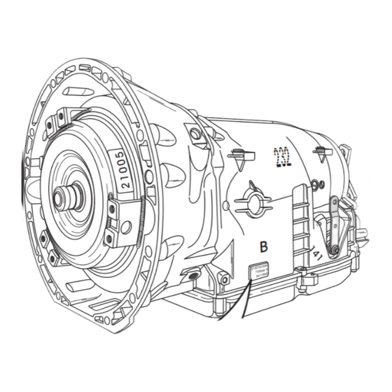
Page 39: Transmission Disassembly
Attempting repairs or service without 2. The standard GM 350 holding fixture works the appropriate training, tools and equipment could just fine on the 722.6 transmission, as shown cause injury to you or others. in Figure 41, which will give you the benefit The service procedures we recommend and of rotating the transmission easily. -
Page 40: Transmission Case Assembly
0.3 - 0.5 mm (.012" - .020") 434 REAR TRANSMISSION SEAL. 435 OUTPUT SHAFT THRUST WASHER. 436 OUTPUT SHAFT DRIVE YOKE. 437 REAR DRIVE YOKE RETAINING NUT. Copyright © 2009 ATSG Copyright © 2009 ATSG Figure 42 Figure 43 AUTOMATIC TRANSMISSION SERVICE GROUP... - Page 41 12 OIL PAN SPACER/CLAMP (5 REQUIRED). 13 OIL PAN. 14 OIL PAN SPACER/CLAMP WITH BRACKET (1 REQUIRED). 15 OIL PAN TO CASE RUBBER GASKET SEAL. Copyright © 2009 ATSG Copyright © 2009 ATSG Figure 44 Figure 45 AUTOMATIC TRANSMISSION SERVICE GROUP...
-
Page 42: Valve Body Assembly
20 CASE SLEEVE SMALL "O" RING SEAL. 21 VALVE BODY RETAINING BOLTS (10 REQUIRED). 16 OIL FILTER ASSEMBLY. 17 OIL FILTER NECK "O" RING SEAL. Copyright © 2009 ATSG Copyright © 2009 ATSG Figure 46 Figure 47 AUTOMATIC TRANSMISSION SERVICE GROUP...
Need help?
Do you have a question about the 722.6 and is the answer not in the manual?
Questions and answers