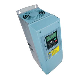
Vacon NX series User Manual
Active front end unit (afe)
air cooled
Hide thumbs
Also See for NX series:
- Applications manual (392 pages) ,
- Maintenance manual (65 pages) ,
- User manual (62 pages)
Table of Contents
Advertisement
Quick Links
Advertisement
Table of Contents


Need help?
Do you have a question about the NX series and is the answer not in the manual?
Questions and answers