Table of Contents
Advertisement
Advertisement
Chapters
Table of Contents

Related Manuals for Hyundai Robex 22-7


Summary of Contents for Hyundai Robex 22-7
- Page 1 SERVICE MANUAL SER. NO. HY2270001~...
- Page 3 INTRODUCTION To insure a long life for the machine and the engine and to prevent failure and prob- lems, proper operation, maintenance and repairs are indispensable. This service manual includes an “outline,” “structure and operation,” “inspection and adjustment,” “disassembly and assembly,” “standard maintenance,” and “repair and re- placement of parts”...
-
Page 5: Table Of Contents
CONTENTS Precautions on Maintenance Outline Attachment Engine Main Pump Hydraulic Oil Filter Control Valve Joystick Slew Motor 10. Travel Motor 11. Hydraulic Cylinder 12. Swivel Joint 13. Crawler 14. Spring Case and Grease Cylinder 15. Idler 16. Sprocket 17. Track Roller 18. -
Page 6: Precautions On Maintenance
1 PRECAUTIONS ON MAINTENANCE 1. Correct operation Correct operation means to follow the correct “procedure” and “method.” Procedure focuses on speed and accuracy of each job. In the method, are addressed what type of facility, tools, instruments, materials, oil should be used, how and which part should be checked, adjusted or disassembled, and what matters to attend to. -
Page 7: Outline
2 OUTLINE CONTENTS 2-1 Location of serial No. 2-2 Name of each part 2-3 Dimensions and specification 2-4 Weight list 2-5 Oil and grease supply points 2-6 List of supply oil and grease 2-7 When to repair 2-8 Hydraulic circuit diagram... - Page 8 2-1 Location of Serial Number...
-
Page 9: Name Of Each Part
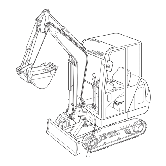
2-2 Name of each part 1. Boom 2. Boom cylinder 3. Arm cylinder 4. Arm 5. Bucket cylinder 6. Bucket links 7. Dump link 8. Bucket 9. Swing frame 10. Engine cover 11. Fuel tank 12. Hydraulic tank 13. Cabin 14. -
Page 10: Dimensions And Specification
2-3 Dimensions and Specifications... - Page 11 Model Robex22-7 Canopy rubber 2,080 Canopy steel 2,130 Machine weight Cabin rubber 2,200 Cabin steel 2,250 Standard bucket capacity/width 0.06 / 450 Type MITSUBISHI L3E Engine Displacement Rated output kW(PS) / min 12.5(17) / 2,400 Overall length 4,075 Dimensions Overall width 1,380 Overall height 2,250...
-
Page 12: Weight List
2-4 Weight list Unit: kg Part name Part name Boom Slew bearing Track frame Bucket Dozer Dump link Crawler(steel) 84×2 Bucket link(R) Crawler(rubber) 59×2 Bucket link(L) Idler 8×2 Boom joint pin Adjust cylinder 12×2 Arm joint pin Track roller 5.0×6 Bucket pin 1.7×2 Sprocket... -
Page 13: Oil And Grease Supply Points
2-5 Oil and grease supply points Boom arm joint pin Fuel tank Hydraulic tank Bucket link pin Engine Bucket pin Travel motor Dozer joint pin Track roller Boom joint pin Adjust cylinder Swing post pin Front idler Swing cylinder Slew gear head pin... - Page 14 2-6 List of lubrication Type of oil according to ambient condition Name Quantity of oil/water -10°C~40°C -20°C~0°C Engine cooling water Soft water (antifreeze is mixed in water) Fuel tank Diesel fuel with freezing point below -7°C (effective capacity) Engine lubricating oil SAE10W-30 Travel motor 0.33...
-
Page 15: When To Repair
2-7 When to repair It is difficult to judge when to perform periodic inspections, maintenance and repairs. Although the wearing rate of each component differs depending on the grade of daily inspection, the skill in machine operation, the working conditions, the quality of used lubricating oil, the frequency of oil replacement, the quality of land to be dug, the digging rate, the schedule for maintenance and repairs should be decided considering the state of engine, the indication of the hour meter, the degree of wear in each part, the state of... -
Page 16: Attachment
2-7-2 Maintenance procedure Inspection and maintenance interval (hours) I n s p e c t i o n a n d maintenance item 1,000 Engine oil pan Check oil Replace the Replace the Clean level engine oil engine oil (New machine only) Replace the Replace the... -
Page 17: Engine
2-7-3 Prestart inspections (1)Prestart inspections Item Remarks Content Engine oil pan Before starting engine Check oil level Check that the fuel level is Fuel tank Check fuel level above the center of level gauge. Check that the amount of water Radiator Check water level in sub-tank is within a specified... - Page 18 Tightening Torque List At prestart inspections, always check the bolts and nuts for looseness. If any bolt or nut is loose, retighten according to the table below. Tightening torque of the bolt and nut (Body) Material 10.9 12.9 Size 12.5 Tightening torque of the hydraulic pipings PT screw PF screw...
- Page 19 2-7-4 Maintenance after the first 50 service hours Item Remarks Content Only for a new machine. After Replace engine oil Engine oil pan and this, every 250 service hours and filter Engine oil filter Only for a new machine. After Engine valve Inspect and adjust this, every 500 service hours...
- Page 20 2-7-6 Maintenance after the first 100 service hours Item Content Remarks Only for a new machine. After Hydraulic line filter Replace the cartridge this, every 500 service hours Hydraulic suction Only for a new machine. After Clean the element filter this, every 500 service hours 2-7-7 Maintenance every 100 service hours Item...
- Page 21 2-7-11 Maintenance every 1,000 service hours Item Content Remarks Engine oil pan Clean engine oil pan Replace the hydraulic oil and clean the oil Clean the inside of the tank Hydraulic oil tank tank Refer to Table of Oil/Grease Lubricating oil of Replace the lubricating Supply Points.
- Page 22 2-8 Hydraulic circuit diagram 2-15...
- Page 23 Item Boom cylinder ø65×ø35 450st Arm cylinder ø65×ø35 500st Bucket cylinder ø60×ø40 400st Swing cylinder ø60×ø35 425st Dozer cylinder ø70×ø40×100st Slew motor 2-160DOS-E3768 Travel motor PHV-190-39-1-8003A Item 10cm /rev 10cm /rev 6.4cm /rev 18.6MPa(190kgf/cm Main 18.6MPa(190kgf/cm relief 17.2MPa(175kgf/cm Port relief 22.5MPa(230kgf/cm Slew 11.8MPa(120kgf/cm...
- Page 25 3 ATTACHMENT CONTENTS 3-1 Standard of maintenance 3-1-1 Attachment 3-2 Inspection and adjustment 3-2-1 Measuring the fall of the attachment of its own weight 3-2-2 Measuring the speed of the attachment cylinder...
- Page 26 3-1 Standard of maintenance 3-1-1 Attachment 1. Swing cylinder 2. Swing cylinder 3. S w i n g p o s t 4. Boom joint head b r a c k e t a n d swing post 5. Boom cylinder 6.
- Page 27 9. Boom/arm joint 10. Bucket cylinder 11. Bucket cylinder 12. Bucket/dump head link joint 13. Arm/bucket link 14. A r m / b u c k e t 15. Dozer joint 16. Dozer cylinder joint joint head 17. Dozer cylinder...
- Page 28 Unit: mm Item Basic Dimension Allowable Clearance Swing cylinder head pin and head bracket ø35 Swing cylinder rod pin and swing post ø35 Swing post pin and bush ø50 Swing post pin and swing post bracket ø50 Boom joint pin and bush ø35 Boom joint pin and swing post ø35...
- Page 29 Unit: mm Criterion Spacer Item Standard Part Number Dimension a b clearance MBU3-00020 ø36×t0.5 Clearance between swing 2.0 ∼ 3.5 MBU3-00021 ø36×t1.0 cylinder head and swing post Clearance between swing 1.0 ∼ 2.5 〃 〃 cylinder rod and head bracket Clearance between swing MBU3-00026 ø51×t0.5...
- Page 30 3-2 Inspection and adjustment 3-2-1 Measuring the natural fall of the attachment 1. Measuring the location of the attachment Set the temperature of the hydraulic oil to 50±5°C. Adjust the height of arm/bucket joint so that it equals that of the boom joint. Then, retract the dozer cylinder to the minimum length and stop the engine.
- Page 31 3-2-2 Measuring the speed of attachment cylinder (at full engine speed and oil temperature 50±5°C) New standard Allowable Condition Machine position Unit value limit BOOM Extend cylinder to the 2.3±0.5 Maximum length 2.3±0.5 Make bucket teeth touch the ground Extend cylinder to the 2.6±0.5 maximum length 2.9±0.5...
- Page 33 4 ENGINE CONTENTS 4-1 Specification 4-2 Performance curve 4-3 Location of serial number 4-3-1 Engine 4-3-2 Standard engine speed...
-
Page 34: Engine
4-1 Specification Engine L3E-W231NSA Type Vertical 4 cycle 3 cylinder Number of cylinders–bore × stroke 3–76 mm×70mm(2.99”× 2.76”) Displacement(cc) 952 cm Ignition order 1–3–2 Overall length 640mm Overall width 450mm Overall height 550 mm Rated output 12.5kW(17ps)/ 2,400 min Maximum torque 55N-m / 1,600min Maximum idling speed(rpm) 2,650 min... -
Page 35: Performance Curve
4-2 Performance curve 55.0 N-m/1,600±100min kgf-m 12.5kW/2,400min 280g/kW-h 260 190 2,650 Engine speed( )×10... -
Page 36: Location Of Serial Number
4-3 Location of serial number 4-3-1 Engine Engine No. (identification plate) 4-3-2 Standard engine speed (at new machine delivery) Conditions Idling speed Maximum idling speed 2,550 Speed when 1P relief is used 2,450... - Page 37 5 MAIN PUMP CONTENTS 5-1 Specification 5-2 Structure 5-3 Removing and installing the pump 5-3-1 Removing the pump 5-3-2 Installing the pump 5-4 Performance test of the hydraulic pump 5-4-1 Measuring instrument 5-4-2 Preparation 5-4-3 Connecting tester 5-4-4 Measuring procedure...
- Page 38 5-1 Specification P3 P2 P1 pump type PVD-08-20L3PS-6G-4920A SAE J518b-1 1/4 PF3/8 Port size PF3/8 PF3/8 221mm 134mm 201.5mm 88mm 45mm 24mm 10mm Displacement(rev) 10mm 6.4mm Rated pressure 18.6MPa(190kgf/cm 18.6MPa(190kgf/cm 17.2MPa(175kgf/cm Direction of rotation Clockwise seen from shaft side Weight 15kg...
-
Page 39: Structure
5-2 Structure 1. Body 15. Spring T1 29. O-ring 2. Body 16. Spring holder 30. Plug 3. Shaft 17. Spring guide 31. Spring pin 4. Cylinder 18. Rod 32. Socket head bolt 5. Valve plate 19. Washer 33. Nut 6. Piston 20. -
Page 40: Removing And Installing The Pump
5-3 Removing and installing the pump 5-3-1 Removing the pump 1. Remove the nipple, TEE, elbow and hoses around the pump. Attach a cap to the removed hoses to keep dust off. Store the nipples and elbows in treated oil. 2. -
Page 41: Performance Test Of The Hydraulic Pump
5-4 Performance test of the hydraulic pump 5-4-1 Measuring instrument Measuring range of flow rate ( / min) 7~ 200 Measuring range of pressure 0 ~ 34.3MPa(350kgf/cm Measuring range of temperature (°C) 0 ~ 150 Port size PF1 O ring type Pressure gauge 49.0MPa(500kg/cm ), 4.9MPa(50kgf/cm... - Page 42 Hydraulic pressure tester Throttle valve CLOSE OPEN...
- Page 43 5-4-5 P-Q characteristic curve How to indicate a pressure value on P-Q characteristic curve. 175 +10 = 100 P _ Q characteristics curve ②P3=17.2MPa(175kgf/cm ①P3=0.98MPa(10kgf/cm 37.2 Rated pressure P 2 ≦18.6MPa...
- Page 45 6 HYDRAULIC OIL FILTER CONTENTS 6-1 Installation 6-2 Hydraulic oil filter 6-2-1 Line filter 6-2-2 Suction filter 6-2-3 Pilot filter 6-3 Maintenance procedure 6-3-1 Replacing the line filter 6-3-2 Replacing the suction filter 6-3-3 How to clean the suction filter...
-
Page 46: Installation
6-1 Installation 右J/S Right J/S 左J/S Left J/S... - Page 47 6-2 Hydraulic oil filter 6-2-1 Line filter (SP08) Filtration accuracy Filtration capacity 50 /min (Max.) Opening pressure 0.15MPa (1.5kgf/cm of bypass valve Proof pressure 0.69MPa (7kgf/cm Oil temperature -20°C~120°C 2-PT1 Tightening torque 19.6Nm(2kgf/m) 6-2-2 Suction filter Grain size 150 mesh Oil temperature -20°C~120°C...
-
Page 48: Pilot Filter
6-2-3 Pilot filter PT 1/4 PT 1/4 Tightening torque: 58.8~78.5N-m (6-8kgf-m) Filtration capacity 2 /min.(Max.) Proof pressure 3.92MPa(40kgf/cm Filtration accuracy Filtration area 5 cm Oil temperature -30°C~120°C... -
Page 49: Maintenance Procedure
6-3 Maintenance procedure 6-3-1 Replacing the line filter 1. Stop the engine. 2. Remove the line filter (6-2-1) with a filter wrench. 3. Check whether any foreign matter is sticking inside the element. If necessary, replace the cartridge assembly. * In general, inspect and maintain line filters after the first 100 service hours, then every 500 service hours. - Page 51 7 CONTROL VALVE CONTENTS 7-1 Specification 7-2 Disassembly and assembly 7-2-1 Replacing the O ring on the contact surface and each block assembly 7-2-2 Replacing the O ring on the spool 7-2-3 Removing the load check valve and replacing the O ring 7-2-4 Replacing the relief valve assembly and the O ring 7-3 Structure of the relief valve...
- Page 52 7-1 Specification Port Port size T1,T2 G 1 / 2 A1~A9, B1~B9, P1 ∼ P3 G 3 / 8 Pa1,Pa2,Pa7,Pa9,P.P G 1/ 4 Pb1,Pb2,Pb7,Pb9,Dr P1 and P2 Main relief pressure 18.6MPa(190kgf/cm )at 24 /min P3 Main relief pressure 17.2MPa(175kgf/cm )at 16 /min A1, B1, A6, B6, A8 Port relief pressure 22.5MPa(230kgf/cm )at 5 /min...
- Page 53 DRIVE:R P.T.O. DRIVE:L BUCKET BOOM TURNING DOZER SWING 1. Control valve assembly 14. Block assembly 2. Block assembly 15. O-ring 3. Block assembly 16. O-ring 4. Block assembly 17. Relief valve assembly 5. Block assembly 18. Relief valve assembly 6. Block assembly 19.
- Page 54 27, 28, 29, 30 FOR DRIVE(R)(L)/SWING P.T.O./DOZER 32, 33, 34 FOR ARM FOR BOOM/BUCKET/TURNING 1. O-ring 15. Cap 2. Wiper ring 16. Socket head bolt 3. Spring seat 17. O-ring 4. Spring 18. Wiper ring 5. Cap screw 19. O-ring 6.
-
Page 55: Disassembly And Assembly
7-2 Disassembly and assembly 7-2-1 Replacing the O ring on the contact surface and each block assembly 1. Loosen the nut of tie rod. 2. Remove each block. Be careful not to damage the machine contact surface. 3. When disassembled, it is recommended to replace the O rings on the contact surface. 4. -
Page 56: Replacing The O Ring On The Spool
7-2-2 Replacing the O ring on the spool 1. On the lever side 1) Remove the mounting screws (1) of the O-ring presser from the block. 2) Replace the backup ring (2) and O-ring (3). 3) When mounting the O-ring presser, be sure not to damage the O-ring. 2. -
Page 57: Structure Of The Relief Valve
7-3 Structure of the relief valve 7-3-1 Main relief valve 1 8 6 4 16 17 Part Tightening torque Cap nut 29.4N-m(3.0kgf-m) Installation of 68.6N-m(7.0kgf-m) the relief valve 14 11 10 1. Cap 7. Adjuster kit 13.O-ring 2. Plug 8. Pilot spring 14.Name plate 3. -
Page 58: Precautions For Handling
7-4 Precautions for handling (Installation and operation should conform to the following items.) 7-4-1 Handling When handling and carrying valves, be careful neither to drop them nor bang the spool end and cap. When stocking a valve for a long time, plug each port to prevent dust and water from entering it. - Page 59 8 JOYSTICK (PILOT VALVE) CONTENTS 8-1 Specification 8-2 Structure...
- Page 60 8-1 Specification Double-Operating Torque 35.7 35.7 25° 19° 3.02 30.8 30.6 30.6 Single-Operating Torque 2.52 25.7 2.14 21.8 20.4 20.4 19.5–1.5 1.91–0.15 1.78 18.2 1.34 13.7 10.2 10.2 –0.1 Secondary 0.95 5–1 0.49 Pressure Push-rod Stroke(mm) Operating Angle 26.5 26° 26° 45°...
- Page 61 8-2 Structure 1. Joystick valve Ass'y 11. Plug 21. Adjiusting nut 2. Casing 12. Push rod 22. Lock nut 3. Port plate 13. Seal 23. Lever 4. Seal washer 14. O-ring 24. Knob 5. O-ring 15. Spring seat 25. Spring pin 6.
-
Page 62: Slew Motor
9 SLEW MOTOR CONTENTS 9-1 Specification 9-2 Structure 9-3 Standard of maintenance 9-3-1 Slew bearing & slew case 9-4 Inspection and adjustment 9-4-1 Measuring the natural slew distance 9-4-2 Measuring the over slew distance after stopping 9-4-3 Measuring the required time for slewing... -
Page 63: Specification
9-1 Specification Direction of rotation (seen from the output shaft) Direction of rotation Oil inlet Oil outlet Clockwise Counterclockwise Port Port size G 3/8 O-ring Port G 3/8 O-ring Port G 3/8 O-ring Port Initial oil replace 500Hr Second and 1,000Hr later replace 25.4... -
Page 64: Structure
9-2 Structure view A-A 1. Slew motor Ass’y 8. Seal, inner face 9. Seal, outer face 2. Seal Kit 3. X-ring 10. O-ring 4. O-ring 11. O-ring 5. Seal, shaft face 12. O-ring 6. O-ring 13. O-ring 7. O-ring 14. Relief valve Assy... -
Page 65: Standard Of Maintenance
9-3 Standard of maintenance 9-3-1 Slew bearing and slew case M10×60 P=1.5 12.9 Tightening torque 80Nm M12×30 P=1.75 12.9 Tightening torque 130Nm M12×40 P=1.75 12.9 Tightening torque 130Nm... -
Page 66: Inspection And Adjustment
9-4 Inspection and adjustment 9-4-1 Measuring the natural slew distance 1. Position of the machine Maintain the hydraulic oil temperature at 50±5°C. Make a slope or use a sleeper to incline the machine by 12°. Set the attachment diagonally, put a weight (W) in the bucket (filling the bucket with soil), retract the arm cylinder to the minimum 12°... -
Page 68: Travel Motor
10 TRAVEL MOTOR CONTENTS 10-1 Specification 10-2 Structure 10-3 Operation 10-4 Handling the travel motor 10-5 Measuring travel motor idling and travelling time 10-6 Inspection and adjustment... - Page 69 10-1 Specification Dr port Dr port B port 231.5 A port PP port 10-M10 2-Rc 1/16 9-M10 (P.G. port) Direction of rotation (viewing from output axis) Direction Oil pouring Oil discharging of rotation port port Clockwise Counterclockwise Port Port size G 3/8 PP,Dr G 1/4...
- Page 70 10-2 Structure 1. Body-1 28. Piston 55. S2 gear 2. Spool 29. Shoe 56. Ring 3. Check valve 30. Shoe holder 57. B2 pin 4. Spring guide 31. Barrel holder 58. O-snap ring 5. Spool 32. Swash plate 59. Thrust plate 1 6.
- Page 71 10-3 Handling the travelling motor Add lubricating oil according to the following procedure. 1. The cover has three plugs. Turn the motor so that oil intake port is the top of the motor. Use them as the oil intake port, oil quantity check port and oil drain port, starting from the top in that order.
- Page 72 10-4 Measuring crawler idling and travelling time 1. Idle crawler for ten turns and measure the required time. Unit : sec Standard value 31±2 High 53±2 (Engine running at full speed and oil temperature of 50±5°C) 2. After travelling 3m on ground level, measure the required time to travel 20m. Standard value 19±2 High...
-
Page 74: Hydraulic Cylinder
11 HYDRAULIC CYLINDER CONTENTS 11-1 Structure 11-2 Disassembly and assembly 11-2-1 Disassembly procedure 11-2-2 Procedure for disassembling inner parts 11-3 Assembly 11-3-1 Assembly procedure 11-3-2 Inspection procedure 11-3-3 Precautions for assembly... - Page 75 11-1 Structure Cylinder Boom Bucket Swing Dozer Item Weight kg Pushing 61.8 52.6 71.6 Trust force* Pulling 43.9 34.7 48.2 Pin diameter (rod) ø35 ø30 Pin diameter (head) mm ø35 ø30 Rod diameter ø35 ø40 Cylinder bore ø65 ø60 ø70 Maximum extended 1,195 1,295...
- Page 76 11-2 Disassembly and assembly The illustration shows a boom cylinder. 1. Cylinder Ass'y 13. Seal ring Ass’y 25. Pin bush 2. Tube 14. Steel ball 26. Dust seal 3. Rod 15. Set screw 27. Cylinder seal 4. Cylinder head 16. Pin bush 28.
- Page 77 11-2-1 Disassembly procedure 1. Hold the cylinder with the vice. Hard wood Tighten the vice carefully; do not deform the cylinder. Blow air alternately from ports A Vice and B and operate the piston rod to drain oil from the cylinder inside. To remove the piston, pull the piston rod about a third of the length.
- Page 78 4. Disassembling the piston assembly Hold the piston rod assembly with a vice. Hard wood • Put the waste between hard wood and the piston to prevent the surface sliding from being damaged. • Set the piston rod assembly on a level block so that it becomes parallel to the level block.
- Page 79 11-3 Assembly 11-3-1 Assembly procedure 1. The assembly procedure is the reverse of disassembly. 2. Before assembly, check whether metallic powder or other foreign matter is not sticking to any of the parts and whether the parts can be reused. 3.
-
Page 80: Swivel Joint
12 SWIVEL JOINT CONTENTS 12-1 Specification and Structure 12-2 Structure, disassembly and assembly... - Page 81 12-1 Specification and Structure 0.3MPa(3kgf/cm Working pressure 3.4Mpa(35kgf/cm A ∼ D, F, P 18.6MPa(190kgf/cm G 1/4 E, F, P, T Screw size(Body) A ∼ D G 3/8 R 1/4 E, F, P, T Screw size(Shaft) A ∼ D R 3/8 Working speed *A to F and P, T denote the position of the port.
- Page 82 12-2 Structure,disassembly and assembly 1. Swivel joint assembly 2. Shaft 3. Pin 4. Hub 5. F ange 6. O-ring 7. O-ring 8. Back up ring 9. Slipper seal 10. O-ring 11. Snap ring 12. Thrust washer 13. Dust seal 14. Socket head bolt 15.
- Page 84 13 CRAWLER CONTENTS 13-1 Structure and operation 13-1-1 Crawler (Steel) 13-1-2 Track frame 13-2 Standard of maintenance 13-2-1 Crawler (Steel) 13-3 Disassembly and assembly 13-3-1 Installing the crawler 13-3-2 Removing the crawler 13-3-3 Track frame spring 13-3-4 Life of the rubber crawler 13-3-5 Handling the rubber crawler...
-
Page 85: Structure And Operation
13-1 Structure and operation 13-1-1 Crawler (steel) Shoe 2. Pin 13-1-2 Track frame 1. Idler 2. Track frame 3. Track roller 4. Spring 13-1... -
Page 86: Standard Of Maintenance
13-2 Standard of maintenance 13-2-1 Crawler (steel) Standard Item Allowance Remarks Unit value Measure by stretching 5 Link pitch links except for the master link Pad or replace Link height Grouser height Pad or replace Pin clearance Replace Bush outer Replace 22.15 diameter... - Page 87 13-3 Disassembly and assembly 13-3-1 Installing the crawler 1. Crawler After the sprocket put on the crawler (2), drive motor to bring it above the idler and for steel crawler, fix the master pin (3) into the hole. For a rubber crawler, the crawler by using the idler as it is.
-
Page 88: Removing The Crawler
13-3-2 Removing the crawler 1. Loosen the crawler. By loosen the cartridge valve (1) of the adjust cylinder, drain grease and loosen the crawler (2). 2. Crawler 1) Lift the main frame with attachment and put blocks under to lift the machine. 2) Turning in the direction of the idler side, remove crawler master pin (3) and then the crawler (2) from track frame. - Page 89 13-3-3 Track frame spring Unit: mm Item Standard Remedy Allowable limit Bend 5 (Overall length of track frame) Deformation of Correct frame 10 (Twist between left and Twist right crawler frames) Opening of idler Standard value Distance between upper and lower Pad or replace 2-1 Track frame faces of idler guide...
-
Page 90: Life Of The Rubber Crawler
13-3-4 Life of the rubber crawler Abrasion loss (mm) Standard life 1000 1500 2000 2500 3000 Service hours (H) Check the remaining life of the rubber crawler by the abrasion loss in the rubber crawler height as shown in the figure below. Note that the life slightly differs depending on the conditions of site and the operation of the machine. -
Page 91: Handling The Rubber Crawler
13-3-5 Handling the rubber crawler 1. Do not run over or turn on a sharp edge If you run over or turn on a projecting sharp edge or a stepped grade, the machine will partially load on the rubber crawler and split it or cut the threads of the rubber crawler and the inner steel cord. -
Page 92: Spring Case And Grease Cylinder
14 SPRING CASE AND GREASE CYLINDER CONTENTS 14-1 Structure 14-2 Specification of spring 14-3 Disassembly and assembly 14-3-1 How to disassemble and assemble the adjust cylinder 14-3-2 How to disassemble and assemble the spring case... -
Page 93: Idler
14-1 Structure 1. Idler folk 7. Back up ring (T2-P30) 2. Cylinder 8. Spacer(DSI) 3. Rod 9. Castle nut 4. Cartridge valve 10. Split pin 5. Grease nipple (PT1/8-C) 11. Spring 6. O-ring (1B-P30) 14-2 Specification of spring Set length L Name Value Name... - Page 94 14-3 Disassembly and assembly 1. Idler folk 7. Back up ring (T2-P30) 2. Cylinder 8. Spacer (DSI) 3. Rod 9. Castle nut 4. Cartridge valve 10. Split pin 5. Grease nipple (PT1/8-C) 11. Spring 6. O-ring (1B-P30) Cylinder effective stroke: 67 mm 14-3-1 How to disassemble and assemble the adjust cylinder 1.
- Page 95 14-3-2 How to disassemble and assemble the spring case 1. Disassembly Lower the spring force between the front idler and adjust cylinder tube using a pressing machine and the special purpose tool. a. Remove the castle nut for the mounting spring. b.
- Page 96 15 IDLER CONTENTS 15-1 Standard of maintenance 15-1-1 Idler...
- Page 97 15-1 Standard of maintenance 15-1-1 Idler Standard No. Item Unit Allowance Remarks value 1 Width of idler teeth Pad or replace 2 Minor diameter ø253 ø241 Pad or replace 3 Number of teeth 4 Quality of lubricating oil cm Engine oil or gear oil 15-1...
-
Page 98: Sprocket
16 SPROCKET CONTENTS 16-1 Disassembly and assembly 16-1-1 Removing the sprocket 16-1-2 Installing the sprocket 16-2 Standard of maintenance 16-2-1 Sprocket... - Page 99 16-1 Disassembly and assembly 16-1-1 Removing the sprocket 1. Crawler Refer to the explanation on crawler removal. 2. Sprocket Remove sprocket mounting bolts (1) and then sprocket (2) from the travelling motor assembly. 16-1-2 Installing the sprocket 1. Sprocket Attach the sprocket to travelling motor assembly and tighten the mounting bolts (1).
- Page 100 16-2 Standard of maintenance 16-2-1 Sprocket Standard Item Unit Allowance Remarks value Width of sprocket teeth Pad or replace Minor diameter of sprocket ø253 ø241 Pad or replace Tightening torque of (M10 P1.5) — sprocket mounting bolt Tightening torque of —...
-
Page 102: Track Roller
17 TRACK ROLLER CONTENTS 17-1 Standard of maintenance 17-1-1 Track roller... - Page 103 17-1 Standard of maintenance 17-1-1 Track roller Standard Item Unit Allowance Remarks value Outer diameter of projected part ø106 ø98 Pad or replace Outer diameter of tread ø86 ø83 Pad or replace Width of projected part Pad or replace Overall width —...
-
Page 104: Electrical Equipment
18 ELECTRICAL EQUIPMENT CONTENTS 18-1 Structure and function 18-1-1 Electric circuit diagram 18-2 Failure and remedy 18-2-1 Starter system 18-2-2 Alternator system... - Page 105 18-1 Structure and function 18-1-1 Electric circuit diagram 18-1...
- Page 106 18-2 Failure and remedy 18-2-1 Starter system Failure Cause Remedy - Disconnection of the wire harness, Reconnect and tighten loose connection of the battery or connections. switch terminal. Pinion does not come out even - Spline which engaged with the Free the spline when the starter switch is pinion of armature shaft is caught...
- Page 107 18-2-2 Alternator system Failure Cause Remedy Reconnect cord-tighten - Cords between terminals are connections. disconnected or connectors are in loose connection. Cannot be charged. Make good earth conections. - Improper earth conection Connect or replace - Brush and slip ring do not contact. Replace - Coil is disconnected or burnt.
- Page 108 19 TROUBLESHOOT- CONTENTS 19-1 Troubleshooting 19-1-1 All functions not operational 19-1-2 Operation power is weak 19-1-3 No operation on boom, arm, bucket slewing 19-2 Travelling system 19-2-1 Right (or left) hand side of crawler does not work correctly 19-2-2 Travelling meander by slow speed on only right (left) hand side 19-2-3 Machine fails to hold on incline 19-3 Slewing system...
-
Page 109: Troubleshooting
19-1 Troubleshooting 19-1-1 All functions not operational If not enough Check the level of Fill up with HYD. oil. HYD. oil. Pumps or couplings Disassemble, check Replace pump Ass'y or faulty. couplings. 19-1-2 Operation power is weak Check the level of If not enough Fill up with HYD. -
Page 110: Boom
19-1-3 No operation on boom, arm, bucket & slewing Check set condition Reset or adjust of safety lock lever. limit switch. Check the wiring, short Faulty Refit wiring. circuit of FUSE BOX- LIMIT SWITCH- SOLENOID VALVE. Replace fuse. Fuse has blown. Check the action of limit switch or solenoid valve. -
Page 111: Travelling System
19-2 Travelling system 19-2-1 Right (or left) hand side of crawler does not work correctly Faulty Check the spool stroke. Check the link system. Faulty Adjustment or replace. Faulty linkage. Replace seals or Faulty action on spool. block Ass'y. Problem changed to Only one opposite direction direction... - Page 112 19-2-2 Travelling meander by slow speed on only right (left) hand side. Is the meander distance within tolerance? Check the tension of Remove any foreign Faulty crawler and check for the matter and re-adjust foreign matter present. to correct tension. Faulty Check the link system.
-
Page 113: Machine Fails To Hold On Incline
19-2-3 Machine fails to hold on incline If you can see any movement (outside tolerance). Problem Replace counter balance solved Replace counter Faulty counter valve (brake valve). balance valve. balance valve. Nothing changed Problem solved Replace drive Replace drive motor. Faulty drive motor. -
Page 114: Slewing System
19-3 Slewing system 19-3-1 No operation both (right/left) slewing. Check the function of Change over relief Faulty slewing operation valves to the other system (dozer, swing). pump port, then test. Low pressure Adjust to correct Faulty relief valve. pressure or replace. Relief valve is sticking Disassemble, clean or replace. - Page 115 19-3-2 It is possible to turn right (left) but not left (right) relieving Change over control Lever moved valve pilot port to left (right). A⇔B, then test. Replace inner parts Faulty control valve block. Problem or valve block. changed to opposite Repair or replace direction...
-
Page 116: Extreme Slow Turning Speed
19-3-4 Extreme slow turning speed Does the turning speed meet the specified speed? Slow Check the action of Check the turning the turning operation circuit pressure. system (dozer, swing). Internal leak on turning motor. Faulty pressure Faulty relief valve. Clean or replace. Change over relief valves to the other pressure... -
Page 117: Boom System(For Arm And Bucket Cylinders The Same Method As Follows)
19-4 Boom system(for arm and bucket cylinders the same method as follows) 19-4-1 No movement on boom cylinder Does Check the movement move Change over boom section of boom for both port A⇔port B directions. Disassemble, replace Faulty port relief valve. seals or replace. - Page 118 19-4-2 Slow action or lack of power on boom cylinder Correct Check the cylinder working speed. Slow Change over relief valve Are the directions port A⇔port B slow (lack of power)? Adjust to correct pressure or replace Faulty relief valve. relief valve.
-
Page 119: Natural Fall Of Boom
19-4-3 Natural fall of boom Check the fall is within tolerance. Change over relief Faulty Internal leak on Replace inner parts valve boom cylinder. or cylinder Ass'y. boom cyl.⇔bucket, then check. Check the internal leak on control valve. Change over hoses Faulty Internal leak on Replace valve... -
Page 120: Swing System
19-5 Swing system 19-5-1 No movement on swing system Operation on just Clean or replace. Faulty suction valve. one direction. Faulty Replace or change over Check the function of the relief valve with the swing operation system other pump's port and (dozer, slewing).
Need help?
Do you have a question about the Robex 22-7 and is the answer not in the manual?
Questions and answers