Table of Contents
Advertisement
INSTALLER: Leave this manual with party responsible for use and operation.
OWNER: Retain this manual for future reference.
NOTICE: DO NOT discard this manual!
Models:
In the Commonwealth of Massachusetts installation must be
performed by a licensed plumber or gas fitter.
See Table of Contents for location of additional Commonwealth
of Massachusetts requirements.
Installation Manual
Installation and Appliance Setup
Heatilator • LEGACY42-IFT Installation Manual • 4095-901 Rev. A • 12/17
WARNING:
FIRE OR EXPLOSION HAZARD
Failure to follow safety warnings exactly
could result in serious injury, death, or
property damage.
• DO NOT store or use gasoline or other flam-
mable vapors and liquids in the vicinity of this
or any other appliance.
• What to do if you smell gas:
- DO NOT try to light any appliance.
- DO NOT touch any electrical switch.
- DO NOT use any phone in your building.
- Leave the building immediately.
- Immediately call your gas supplier from
a neighbor's phone. Follow the gas sup-
plier's instructions.
- If you cannot reach your gas supplier, call
the fire department.
• Installation and service must be performed
by a qualified installer, service agency, or the
gas supplier.
1
Advertisement
Table of Contents

Subscribe to Our Youtube Channel
Related Manuals for Heatilator LEGACY42-IFT


Summary of Contents for Heatilator LEGACY42-IFT
- Page 1 In the Commonwealth of Massachusetts installation must be performed by a licensed plumber or gas fitter. See Table of Contents for location of additional Commonwealth of Massachusetts requirements. Heatilator • LEGACY42-IFT Installation Manual • 4095-901 Rev. A • 12/17...
-
Page 2: Table Of Contents
C. Optional Accessories ......47 = Contains updated information. Heatilator • LEGACY42-IFT Installation Manual • 4095-901 Rev. A • 12/17... -
Page 3: Installation Standard Work Checklist
_____________________________________________________________________________________ _________________________________________________________________________________________________ _________________________________________________________________________________________________ Comments Communicated to party responsible ____________________ by ______________________on ___________ (Builder / Gen. Contractor/) (Installer) (Date) = Contains updated information. 4095-982 Rev. A 01/18 Heatilator • LEGACY42-IFT Installation Manual • 4095-901 Rev. A • 12/17... -
Page 4: Product Specific And Important Safety Information
• A 110-120 VAC circuit for this product must be pro- tected with ground-fault circuit-interrupter protection, in compliance with the applicable electrical codes, when it is installed in locations such as in bathrooms or near sinks. Heatilator • LEGACY42-IFT Installation Manual • 4095-901 Rev. A • 12/17... -
Page 5: Requirements For The Commonwealth Of Massachusetts
VENT DIRECTLY BELOW. KEEP CLEAR OF ALL OB- of the installation. STRUCTIONS”. See Gas Connection section for additional Common- wealth of Massachusetts requirements. Heatilator • LEGACY42-IFT Installation Manual • 4095-901 Rev. A • 12/17... -
Page 6: Getting Started
Level Reciprocating saw Flat blade screwdriver Non-corrosive leak check solution Caulking material (300ºF minimum continuous exposure rating) 1/2 - 3/4 in. length, #6 or #8 self-drilling screws Heatilator • LEGACY42-IFT Installation Manual • 4095-901 Rev. A • 12/17... -
Page 7: Negative Pressure
• Avoid installing the appliance in locations where fans, windows or drafts can impact appliance performance. • Installation of optional outside air kits. Heatilator • LEGACY42-IFT Installation Manual • 4095-901 Rev. A • 12/17... -
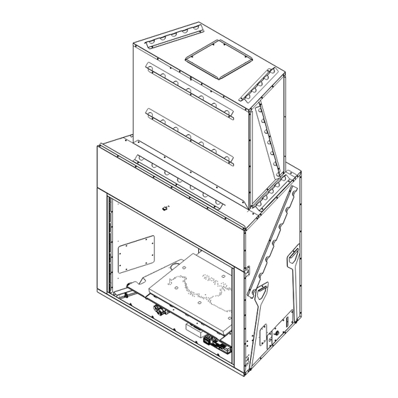
Page 8: Framing And Clearances
1-7/8 in ELECTRICAL (1068 mm) (161 mm) (46 mm) ACCESS 15-1/2 in 50-3/8 in GAS LINE ACCESS (395 mm) OUTSIDE AIR (1280 mm) OUTSIDE AIR Figure 3.1 Appliance Dimensions Heatilator • LEGACY42-IFT Installation Manual • 4095-901 Rev. A • 12/17... - Page 9 28-3/8 in 23-3/8 in (721 mm) (72 mm) 2-1/2 in (64 mm) 2 in (51 mm) 37 in (938 mm) 42 in (1065 mm) Figure 3.2 Decorative Front Dimensions Heatilator • LEGACY42-IFT Installation Manual • 4095-901 Rev. A • 12/17...
-
Page 10: Clearances To Combustibles
Vert Term 51-3/8 in. (1305 mm) 1 in. (25 mm) appliance to 68-1/2 in. combustibles 64-3/4 in. (1739 mm) (1645 mm) No elbows Horiz Term Figure 3.3 Appliance Locations Heatilator • LEGACY42-IFT Installation Manual • 4095-901 Rev. A • 12/17... - Page 11 * Add 9-1/4 inches to framing depth for an elbow vented off the rear of the appliance. Figure 3.4 Clearances to Combustibles Heatilator • LEGACY42-IFT Installation Manual • 4095-901 Rev. A • 12/17...
-
Page 12: Tv Good Faith Guidelines
“A” and“C” dimension taken from the top of the fireplace opening. Sugges ons on how to further reduce TV temperatures: Increase “A” dimension. Increase “C” dimension. Figure 3.5 Good Faith Clearances Heatilator • LEGACY42-IFT Installation Manual • 4095-901 Rev. A • 12/17... -
Page 13: Constructing The Appliance Chase
• The chase must be properly blocked to prevent blown insulation or other combustibles from entering and making contact with fireplace or chimney. • Failure to maintain airspace may cause overheating and a fire. Heatilator • LEGACY42-IFT Installation Manual • 4095-901 Rev. A • 12/17... -
Page 14: Termination Location And Vent Information
Note: A vent shall not terminate directly above a sidewalk or paved driveway which is located between two single family dwellings and serves Wall Height 8’ (96”) both dwellings. (cont.) Figure 4.1 Minimum Clearances for Termination Heatilator • LEGACY42-IFT Installation Manual • 4095-901 Rev. A • 12/17... - Page 15 • Hearth & Home Technologies assumes no responsibility for the improper performance of the appliance when the venting system does not meet these requirements. Figure 4.2 Minimum Clearances for Termination Heatilator • LEGACY42-IFT Installation Manual • 4095-901 Rev. A • 12/17...
-
Page 16: Approved Pipe
(399 mm) Figure 4.3 shows the vertical and horizontal offsets for SLG elbows. 15-3/4 in (399 mm) 90º SLG Elbows Figure 4.3 Vertical and Horizontal Offset for SLG Elbows Heatilator • LEGACY42-IFT Installation Manual • 4095-901 Rev. A • 12/17... -
Page 17: Measuring Standards
Vertical Pipe Inches Millimeters Inches Millimeters SLG4 8-7/8 18-5/8 SLG6 10-1/4 SLG12 14-1/2 24-1/4 SLG24 32-3/4 SLG36 31-1/2 41-1/4 1048 SLG48 39-7/8 1013 49-5/8 1260 Figure 4.4 Elbow Chart Heatilator • LEGACY42-IFT Installation Manual • 4095-901 Rev. A • 12/17... -
Page 18: Vent Diagrams
The wall where the termination cap is located requires a wall shield only on the interior side. •Horizontal runs of vent do not require vertical rise; horizontal runs may be level. Figure 4.5 Venting Heatilator • LEGACY42-IFT Installation Manual • 4095-901 Rev. A • 12/17... - Page 19 WARNING: Elbows may NOT be installed in a downward direction. Elbow installed horizontally Elbow installed vertically Figure 4.6 Elbow installation Options Heatilator • LEGACY42-IFT Installation Manual • 4095-901 Rev. A • 12/17...
-
Page 20: Vent Clearances And Framing
Use DVP-WS (wall shield) for all interior wall penetra- tions Wall Figure 5.1 Horizontal Venting Clearances To Combustible Figure 5.2 Non-Combustible Wall Penetration Materials Heatilator • LEGACY42-IFT Installation Manual • 4095-901 Rev. A • 12/17... - Page 21 *Shows center of vent framing hole for top or rear venting. The center of the hole is one (1) in. (25.4 mm) above the center of the horizontal vent pipe. Figure 5.3 Wall Penetration Heatilator • LEGACY42-IFT Installation Manual • 4095-901 Rev. A • 12/17...
-
Page 22: Ceiling Firestop/Floor Penetration Framing
Figure 5.3 Installing Ceiling Firestop INSTALL ATTIC INSULATION SHIELDS BEFORE OR AFTER INSTALLATION OF VENT SYSTEM CEILING FIRESTOP CEILING FIRESTOP INSTALLED BELOW CEILING INSTALLED ABOVE CEILING Figure 5.4 Installing the Attic Shield Heatilator • LEGACY42-IFT Installation Manual • 4095-901 Rev. A • 12/17... -
Page 23: Appliance Preparation
Figure 6.4 • Install the cover plate and vent collar with insulation to the top of the appliance and replace (8) screws. Figure 6.2 Figure 6.5 Heatilator • LEGACY42-IFT Installation Manual • 4095-901 Rev. A • 12/17... -
Page 24: Securing And Leveling The Appliance
UL181 Class 0 or Class 1 rigid or flexible ducting. • Secure flex duct with metal tape, screws, or wire ties. Nailing Tabs (both sides) Figure 6.6 Proper Positioning and Securing of an Appliance Heatilator • LEGACY42-IFT Installation Manual • 4095-901 Rev. A • 12/17... -
Page 25: Venting And Chimneys
See Figure 7.3 • Secure pipe sections together with a minimum of three Lances screws Notice: Chimney sections cannot be disassembled once locked together. Plan ahead! Figure 7.3 Heatilator • LEGACY42-IFT Installation Manual • 4095-901 Rev. A • 12/17... -
Page 26: Assemble Slip Sections
SLG vent section and slip section is maintained. Figure 7.6 Securing Vertical Pipe Sections 120º Secure minimum (3) screws Figure 7.5 Screws into Slip Section Figure 7.7 Securing Horizontal Pipe Sections Heatilator • LEGACY42-IFT Installation Manual • 4095-901 Rev. A • 12/17... -
Page 27: Vertical Termination Requirements
• DO NOT remove the heat shields attached to the wall shield or the termination cap (shown in Figure 7.8). • Heat shields must overlap 1-1/2 in. (38 mm) minimum. Heatilator • LEGACY42-IFT Installation Manual • 4095-901 Rev. A • 12/17... - Page 28 • When installing a horizontal termination cap, follow the cap location guidelines as prescribed by current ANSI Z223.1 and CAN/CGA-B149 installation codes and refer to Section 4 of this manual. Wall Shield Figure 7.12 Heatilator • LEGACY42-IFT Installation Manual • 4095-901 Rev. A • 12/17...
- Page 29 Secure with screws. See Figure 7.17. (8) screws Louvered Cover Figure 7.14 Motor • Remove motor assembly from cap base (8) screws. Assembly See Figure 7.15. Figure 7.17 Figure 7.15 Heatilator • LEGACY42-IFT Installation Manual • 4095-901 Rev. A • 12/17...
-
Page 30: Shrouds
The use of a decorative only shroud is permitted on Figure 7.19 LEGACY appliances that terminate from a vertical chase type structure. Enclosing the termination cap within the decorative shroud is NOT permitted. Heatilator • LEGACY42-IFT Installation Manual • 4095-901 Rev. A • 12/17... -
Page 31: Electrical Information
Accessory Cable Installation • Remove side access cover, (2) screws. See Figure 8.1. Accessory Cable Wires Figure 8.3 Connectors Figure 8.1 Access Cover Heatilator • LEGACY42-IFT Installation Manual • 4095-901 Rev. A • 12/17... -
Page 32: Wiring Requirements
LEGACY appliance junction box to a switched circuit. • Refer to Figure 8.9, LEGACY Wiring Diagram. • This appliance is equipped with an Intellifire touch control system which operates on a 6VDC system. Heatilator • LEGACY42-IFT Installation Manual • 4095-901 Rev. A • 12/17... - Page 33 Figure 8.9 Wiring Diagram Heatilator • LEGACY42-IFT Installation Manual • 4095-901 Rev. A • 12/17...
-
Page 34: Gas Information
1/2 in. (13 mm) T-handle manual shut-off valve and flexible gas connector are connected to the 1/2 in. (13 mm) control valve inlet. • If substituting for these components, please consult local codes for compliance. Heatilator • LEGACY42-IFT Installation Manual • 4095-901 Rev. A • 12/17... -
Page 35: High Altitude Installations
(approximately 20-40 minutes). CAUTION! Risk of Burns! Components are HOT. Wear protective gloves when adjusting shutter. Fig 9.1 Air Shutter Natural Gas Fig 9.2 Air Shutter Removed Propane Gas Heatilator • LEGACY42-IFT Installation Manual • 4095-901 Rev. A • 12/17... -
Page 36: Finishing
High Temperature Sealant (300º F/149º C min.) Top and Seal Joint Figure 10.3 Combustible Mantel Leg or Wall Projections (Acceptable on both sides of opening) Figure 10.1 High Temperature Sealant Heatilator • LEGACY42-IFT Installation Manual • 4095-901 Rev. A • 12/17... -
Page 37: Decorative Front Dimensions For Finishing
Decorative Front Non-combustible finishing material 12 in. maximum thickness Stop finishing material flush with appliance opening. Figure 10.4 Non-Combustible Finishing Material (top and sides of appliance) Heatilator • LEGACY42-IFT Installation Manual • 4095-901 Rev. A • 12/17... -
Page 38: Appliance Setup
• Remove (2) Hearth Refractory Brackets and Grate The S1 LED, located on the top of the speed control, Assembly from Burner Cover for installation later. becomes illuminated. Heatilator • LEGACY42-IFT Installation Manual • 4095-901 Rev. A • 12/17... -
Page 39: Refractory Kit
The LEGACY refractory kit includes the following com- ponents: • Back Refractory • Left & Right Side Refractory • Left & Right Side Hearth Refractory • Left, Right & Middle Front Hearth Refractory Figure 11.5 Heatilator • LEGACY42-IFT Installation Manual • 4095-901 Rev. A • 12/17... - Page 40 Install Left & Right Side Hearth Refractory Brackets, as shown, and secure with (3) screws each. See Fig- ure 11.7. Front Hearth Refractory Grate Assembly Figure 11.9 Hearth Refractory Bracket Figure 11.7 Heatilator • LEGACY42-IFT Installation Manual • 4095-901 Rev. A • 12/17...
-
Page 41: Log Installation Instructions
Figure 11.13. • Install right front log on the two locating pins on the burner top. See Figure 11.11 Right Front Log Left Front Log Figure 11.13 Figure 11.11 Heatilator • LEGACY42-IFT Installation Manual • 4095-901 Rev. A • 12/17... - Page 42 • Once the bulb is installed, clean the surface of the bulb with a soft cloth and Isopropyl rubbing alcohol to remove any fingerprints. Left Top Log Figure 11.15 Heatilator • LEGACY42-IFT Installation Manual • 4095-901 Rev. A • 12/17...
-
Page 43: Place The Mineral Wool
Mineral wool pilot carryover may be used to ports. cover all other burner ports. Lava Rock and Vermiculite Figure 11.17 Placement of Mineral Wool, Lava Rock and Vermiculite Heatilator • LEGACY42-IFT Installation Manual • 4095-901 Rev. A • 12/17... -
Page 44: Reference Materials
(508 MM) 14 IN. (356 MM) 6 in. (152 mm) 12 IN. (305 MM) DVP-RDS ROOF DECK INSULATION SHIELD DVP-WS (Wall Shield) (Interior wall penetrations only) Figure 12.1 Vent Components Heatilator • LEGACY42-IFT Installation Manual • 4095-901 Rev. A • 12/17... -
Page 45: Termination Cap
Effective Length 16 in. 4 in. 7 in. (406 mm.) 102 mm 178 mm 11 in. Effective 279 mm. Length Termination Cap (included with appliance) Figure 12.2 Vent Components Heatilator • LEGACY42-IFT Installation Manual • 4095-901 Rev. A • 12/17... - Page 46 19-3/8 in. (491 mm) DVP-TRAPFL SLG-BEK Flashing Brick Extension Kit 26 in. (660 mm) DVP-HSM-B Extended Heat Shield 26 in. (600 mm) SLG-D-EXT Collar Extension Figure 12.3 Vent Components Heatilator • LEGACY42-IFT Installation Manual • 4095-901 Rev. A • 12/17...
-
Page 47: Accessories
42 in. (1067 mm) Outside Air Hood ID4 4 in. Insulated Duct AK22 Outside Air Kit UD4 4 in. Uninsulated Duct GV80BK Mesh Door Kit Figure 12.3 Optional Accessories Heatilator • LEGACY42-IFT Installation Manual • 4095-901 Rev. A • 12/17... - Page 48 Street West, Lakeville, MN 55044 www.heatilator.com Please contact your Heatilator dealer with any questions or concerns. For the location of your nearest Heatilator dealer, please visit www.heatilator.com. Printed in U.S.A. - Copyright 2017 Heatilator • LEGACY42-IFT Installation Manual • 4095-901 Rev. A • 12/17...
Need help?
Do you have a question about the LEGACY42-IFT and is the answer not in the manual?
Questions and answers