
Subscribe to Our Youtube Channel
Related Manuals for SEW MOVIFIT SC series


Summary of Contents for SEW MOVIFIT SC series
- Page 1 Gearmotors \ Industrial Gear Units \ Drive Electronics \ Drive Automation \ Services ® MOVIFIT Edition 02/2007 perating nstructions 11574615 / EN...
- Page 2 SEW-EURODRIVE – Driving the world...
-
Page 3: Table Of Contents
Contents 1 General Information ..................5 Structure of the safety notes ..............5 Right to claim under warranty ..............5 Exclusion of liability ................... 5 2 Safety Notes ...................... 6 General information .................. 6 Target group ..................... 6 Designated use ..................6 Other applicable documentation ............... - Page 4 Contents 9 Service ......................116 Unit diagnostics..................116 SEW Electronics Service ..............119 Disposal ....................119 10 Technical Data ....................120 10.1 CE marking, UL approval and C-Tick............ 120 10.2 General technical data ................121 10.3 General electronics data ............... 123 10.4 Digital inputs ..................
-
Page 5: General Information
MOVIFIT SC and to achieve the specified product and perfor- mance features. SEW-EURODRIVE assumes no liability for injury to persons or damage to equipment or property resulting from non-observance of these operating instructions. In such cases, any liability for defects is excluded. -
Page 6: Safety Notes
If you are unclear about any of the informa- tion in this documentation, or if you require further information, please contact SEW- EURODRIVE. -
Page 7: Other Applicable Documentation
SC may not perform any safety functions unless they are described and expressly approved. Use only components in safety applications that were explicitly delivered in this version by SEW-EURODRIVE. Other applicable documentation The following publication must also be observed: •... -
Page 8: Safe Disconnection
Safety Notes Safe disconnection Safe disconnection ® MOVIFIT SC meets all requirements for safe disconnection of power and electronic connections in accordance with EN 61800-5-1. All connected circuits must also satisfy the requirements for safe disconnection. Operation ® Systems into which MOVIFIT SC is installed must be equipped with additional moni- toring and protection devices, if necessary, according to the applicable safety regula- tions;... -
Page 9: Index Of Changes
Index of Changes Changes compared to the previous version Index of Changes Changes compared to the previous version The following section lists the main changes made to the individual sections from edition 08/2006, part number 11486619 (EN). Section "Gear • New section "Overview"... - Page 10 Index of Changes Changes compared to the previous version Section • New section "Digital output DB00...DB01" "Technical Data" • Changes to section "Interfaces": – New subsection "PROFINET interface" – New subsection "DeviceNet interface" • New section "Cable type A hybrid cables": plus •...
-
Page 11: Unit Design
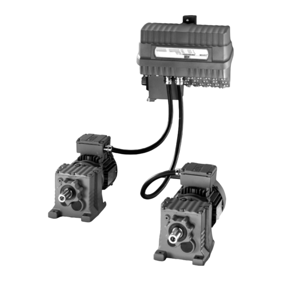
Unit Design Overview Unit Design Overview ® The following figure depicts the MOVIFIT versions described in these operating instructions: EBOX (active electronics unit) ABOX (passive connection unit) MTS...-..-00 MTA...-S02.-...-00 ® MOVIFIT ® MOVIFIT with integrated motor starter Connection box with terminals and cable glands MTA...-S12.-...-00 MTA...-S22.-...-00... -
Page 12: Ebox (Active Electronics Unit)
Unit Design EBOX (active electronics unit) EBOX (active electronics unit) ® The MOVIFIT SC EBOX is a closed electronics unit with communication interface, I/Os, and motor starter: EBOX " MTS...-..-00" 1 2 3 4 5 6 61128AXX [1] Central opening/closing mechanism [2] Operation LEDs for I/Os (can be labeled), communication, and unit status [3] Connection to connection box [4] DIP switch S10 for unit functions... -
Page 13: Abox (Passive Connection Unit)
Unit Design ABOX (passive connection unit) ABOX (passive connection unit) 4.3.1 ABOX with terminals and cable glands "MTA...-S02.-...-00" ® The following figure depicts the MOVIFIT ABOX with terminals and cable glands: ABOX "MTA...-S02.-...-00" [10] 61091AXX [1] Mounting rail [2] Connection to EBOX [3] Protection cover [4] Maintenance switch [5] DIP switch S1 for bus termination (PROFIBUS version only) - Page 14 Unit Design ABOX (passive connection unit) 4.3.2 Hybrid ABOX "MTA...-S12.-...-00" and "MTA...-S22.-...-00" ® The following figure depicts the MOVIFIT hybrid ABOX with M12 SPEEDCON connec- tions, terminals, and cable glands: NOTE The following depicts the connection technology of the PROFIBUS version as an example: For detailed information about additional variants, refer to the section "Instal- lation".
- Page 15 Unit Design ABOX (passive connection unit) ® 4.3.3 HanModular ABOX "MTA...-H12.-...-00" and "MTA...-H22.-...-00" ® ® The following figure depicts the HanModular connection box with HanModular plug connector and M12 plug connector: NOTE The following depicts the connection technology of the PROFIBUS version as an example: For detailed information about additional variants, refer to the section "Instal- lation".
-
Page 16: Hygenic Plus Version (Optional)
Unit Design Hygenicplus version (optional) plus Hygenic version (optional) 4.4.1 Features plus The Hygenic version has the following characteristics: ® • IP66 in accordance with EN 60529 and IP69K according to DIN 40050-9 (MOVIFIT housing closed and all cable glands sealed according to the relevant enclosure) •... - Page 17 Unit Design Hygenicplus version (optional) ® The following figure depicts the additional features of MOVIFIT units in the optional plus Hygenic version: EBOX " MTS12...-..-00" ABOX "MTA12...-S02.-...-00" [10] [11] 61158AXX EBOX with special surface treatment (only available in one color) Signal plug connector with gasket Gasket between ABOX and coverplate Power plug connector with gasket...
-
Page 18: Unit Designation Movifit® Sc
Unit Design Unit designation MOVIFIT® SC ® Unit designation MOVIFIT Example EBOX nameplate 61160AXX [A] External nameplate [B] Inner nameplate [1] EBOX status field MT S 11 A 015- 50 3 - P1 0 A - 00 EBOX version 00 = Series Version Function level... - Page 19 Unit Design Unit designation MOVIFIT® SC Example ABOX nameplate 61154AXX [1] ABOX status field MT A 11 A - 50 3 -S02 1 - D 01 - 00 ABOX version 00 = Series Maintenance switch type 01 = With rotary button (ABB) Maintenance switch type Switch disconnector Fieldbus...
-
Page 20: Mechanical Installation
Mechanical Installation Installation instructions Mechanical Installation Installation instructions ® • Mount MOVIFIT only on a level, vibration-proof and torsionally rigid support structure, as described in the section "Approved installation position". • Use suitable fittings for the cables (use reducing adapters if necessary). With connector plug versions, you must use a suitable mating connector. -
Page 21: Installation Notes
Mechanical Installation Installation notes Installation notes 1. Drill holes for mounting the four screws to the mounting surface according to the following figure: min. 50 334.5 61182AXX NOTES • [1] Note the minimum installation clearance so that the EBOX can be removed from the ABOX. - Page 22 Mechanical Installation Installation notes 2. Insert four screws into the mounting surface. We recommend size M6 screws and depending on the base, dowel pins, if necessary. 57136AXX 3. Mount ABOX with mounting platform on screws. 61386AXX ® Operating Instructions – MOVIFIT...
- Page 23 Mechanical Installation Installation notes 4. Tighten the screws CAUTION! Hazard from falling load Minor injuries • You will have to tighten at least the upper two of the four wall screws to ensure a secure fit after mounting. 59559AXX ® Operating Instructions –...
-
Page 24: Central Opening/Closing Mechanism
Mechanical Installation Central opening/closing mechanism Central opening/closing mechanism STOP! If the torque is too high, the central opening/closing mechanism can be destroyed. • It is essential that you do not exceed a maximum torque of 7 Nm when closing. The enclosure specified in the technical data only applies when a unit is mounted ®... - Page 25 Mechanical Installation Central opening/closing mechanism ® 5.4.2 Notes on closing the MOVIFIT ® The MOVIFIT is closed correctly when the redirector of the closing mechanism [2] is on the mounting plate [1]. 60932AXX ® Operating Instructions – MOVIFIT...
-
Page 26: Tightening Torques
Mechanical Installation Tightening torques Tightening torques Ensure a tightening torque of 2.5 Nm for the blanking plugs [1] supplied by SEW- EURODRIVE and the screw plug using the diagnostic interface [2]: 61148AXX [1] Blanking plug cable entry [2] Diagnostic interface screw plug ®... -
Page 27: Hygenicplus Version
In case of damage, contact SEW-EURODRIVE. • Use only cable glands or screw plugs that correspond with the enclosure. Glands and screw fittings available from SEW EURODRIVE can be found in the section "Tech- nical Data" on page 131. •... - Page 28 Mechanical Installation Hygenicplus version 5.6.2 Tightening torques Central open- The permitted tightening torque for the central opening/closing mechanism is 7 Nm. ing/closing mechanism 60904AXX NOTE Also observe the notes in the section "Central opening/closing mechanism" starting on page 24. EMC cable glands Observe the permitted tightening torque in the table for EMC cable glands: 60908AXX Screw fitting...
- Page 29 Mechanical Installation Hygenicplus version Blanking plugs The permitted tightening torque for blanking plugs is 2.5 Nm: 60902AXX ® Operating Instructions – MOVIFIT...
-
Page 30: Electrical Installation
– Must be connected to a wide area of the unit's metal housing at the cable ends (see also 37 and page 38). NOTE Additional information is available in the SEW publication "Drive Engineering – Prac- tical Implementation: Electromagnetic Compatibility (EMC) in Drive Engineering". ®... -
Page 31: Installation Instructions (All Versions)
> 3.5 mA can occur. • SEW-EURODRIVE recommends that you do not use earth-leakage circuit breakers. However, if an earth-leakage circuit breaker (FI) is stipulated as a direct or indirect touch guard, observe the following note in accordance with EN 61800-5-1: WARNING Wrong type of earth-leakage circuit breaker installed. - Page 32 Electrical Installation Installation instructions (all versions) 6.2.4 Notes on PE connection and/or equipotential bonding DANGER Faulty PE connection Severe or fatal injuries or damage to property from electric shock. • The permitted tightening torque for the fitting is 2.0 to 2.4 Nm (18...21 lb-in). •...
- Page 33 Electrical Installation Installation instructions (all versions) 6.2.6 Meaning of the 24 V voltage levels ® MOVIFIT SC has a total of 3 different 24 V potential levels, which are electrically isolated from each other: • 1) 24V_C: C = Continuous •...
- Page 34 Electrical Installation Installation instructions (all versions) 6.2.7 Plug connector ® All MOVIFIT plug connectors are illustrated in these operating instructions with a contact end view. 6.2.8 Protection devices ® MOVIFIT drives are equipped with integrated overload protection devices, which make external devices obsolete.
-
Page 35: Abox With Terminals And Cable Glands "Mta
Electrical Installation ABOX with terminals and cable glands "MTA...-S02.-...-00" ABOX with terminals and cable glands "MTA...-S02.-...-00" The following figure depicts the connection box with terminals and cable glands "MTA…- S02.-…-00": MTA...-S02.-...-00 61095AXX 6.3.1 Additional installation instructions for "MTA...-S02.-...-00" Permitted connection Terminal data X1 / X20 X8 / X9... - Page 36 Electrical Installation ABOX with terminals and cable glands "MTA...-S02.-...-00" Enabling the terminals Terminals X1, X20 Connecting conductors without a screw driver Connecting conductors with a screw driver 57975AXX 57977AXX 1) Single-wire conductors and flexible conductors with conductor end sleeves can be installed directly (without using a tool) up to two cross-section sizes below the rated cross-section.
- Page 37 Electrical Installation ABOX with terminals and cable glands "MTA...-S02.-...-00" Connection of the Observe the following guidelines compiled by the PROFIBUS Nutzerorganisation e.V. PROFIBUS cable (user organization) when installing the PROFIBUS (Internet: www.profibus.com): ® in MOVIFIT • "Installation guidelines for PROFIBUS DP/FMS", order number 2.111 (German) or 2.112 (English) •...
- Page 38 Electrical Installation ABOX with terminals and cable glands "MTA...-S02.-...-00" Connecting the • We recommend using the shielded and pre-fabricated SEW hybrid cables specifi- ® hybrid cables cally designed for connecting MOVIFIT and motor (see page 87). • The outer shield of the hybrid cable must be attached to the housing of the unit using a suitable EMC cable gland.
- Page 39 Electrical Installation ABOX with terminals and cable glands "MTA...-S02.-...-00" 6.3.2 Fieldbus/option-independent terminal assignment DANGER The maintenance switch only disconnects the integrated motor circuit breaker from the ® mains. Voltage is still present on the terminals of the MOVIFIT unit. Severe or fatal injuries from electric shock. ®...
- Page 40 Electrical Installation ABOX with terminals and cable glands "MTA...-S02.-...-00" 1 2 3 4 2 3 4 5 6 7 8 1 2 3 4 5 6 7 8 1 2 3 4 11 12 13 14 11 12 13 14 15 16 17 18 21 22 23 24 21 22 23 24 25 26 27 28 11 12 13 14...
- Page 41 Output motor 1 phase V W_M1 Output motor 1 phase W 15_M1 Connection for SEW brake motor 1 terminal 15 (blue) 14_M1 Connection for SEW brake motor 1 terminal 14 (white) 13_M1 Connection for SEW brake motor 1 terminal 13 (red)
- Page 42 • The terminal assignment "X29" illustrated here applies as of status 11 of the wiring board. If you use a wiring board with another status, consult SEW-EURODRIVE. • The status of the wiring board is indicated in the first status field of the ABOX name- plate.
- Page 43 Electrical Installation ABOX with terminals and cable glands "MTA...-S02.-...-00" 1 2 3 4 1 2 3 4 1 2 3 4 5 6 7 8 1 2 3 4 5 6 7 8 1 2 3 4 11 12 13 14 11 12 13 14 15 16 17 18 21 22 23 24 21 22 23 24 25 26 27 28...
- Page 44 Electrical Installation ABOX with terminals and cable glands "MTA...-S02.-...-00" 1 2 3 4 1 2 3 4 1 2 3 4 5 6 7 8 1 2 3 4 5 6 7 8 1 2 3 4 11 12 13 14 11 12 13 14 15 16 17 18 21 22 23 24 21 22 23 24 25 26 27 28...
- Page 45 Electrical Installation ABOX with terminals and cable glands "MTA...-S02.-...-00" 1 2 3 4 1 2 3 4 5 6 7 8 1 2 3 4 5 6 7 8 1 2 3 4 11 12 13 14 11 12 13 14 15 16 17 18 21 22 23 24 21 22 23 24 25 26 27 28 11 12 13 14...
- Page 46 Electrical Installation ABOX with terminals and cable glands "MTA...-S02.-...-00" 6.3.3 Option-independent terminal assignment I/O terminals X45 1 2 3 4 1 2 3 4 1 2 3 4 5 6 7 8 1 2 3 4 5 6 7 8 1 2 3 4 11 12 13 14 11 12 13 14 15 16 17 18...
- Page 47 Electrical Installation ABOX with terminals and cable glands "MTA...-S02.-...-00" 6.3.4 Fieldbus-independent terminal/pin assignment PROFIBUS terminal assignments 1 2 3 1 2 3 4 1 2 3 4 1 2 3 4 5 6 7 8 1 2 3 1 2 3 4 5 6 7 8 1 2 3 4 11 12 13 14 11 12 13 14 15 16 17 18...
- Page 48 Electrical Installation ABOX with terminals and cable glands "MTA...-S02.-...-00" Pin assignment Ethernet 1 2 3 4 1 2 3 4 5 6 7 8 1 2 3 4 5 6 7 8 1 2 3 4 11 12 13 14 11 12 13 14 15 16 17 18 21 22 23 24 21 22 23 24 25 26 27 28...
- Page 49 Electrical Installation ABOX with terminals and cable glands "MTA...-S02.-...-00" DeviceNet terminal/pin assignment 1 2 3 4 5 1 2 3 4 1 2 3 4 5 6 7 8 1 2 3 4 5 6 7 8 1 2 3 4 11 12 13 14 11 12 13 14 15 16 17 18 21 22 23 24...
-
Page 50: Hybrid Abox "Mta
Electrical Installation Hybrid ABOX "MTA...-S12.-...-00" and "MTA...-S22.-...-00" Hybrid ABOX "MTA...-S12.-...-00" and "MTA...-S22.-...-00" The following figure depicts the Hybrid ABOX "MTA...-S12.-...-00" and "MTA...-S22.-...-00": MTA...-S12.-...-00 MTA...-S22.-...-00 61106AXX 6.4.1 Additional installation instructions for "MTA...-S12.-...-00" and "MTA...-S22.-...-00" Permitted connection Terminal data X1 / X20 X8 / X9 X81 / X91 / X29 cross-section... - Page 51 Electrical Installation Hybrid ABOX "MTA...-S12.-...-00" and "MTA...-S22.-...-00" Terminal Connecting conductors with a screw driver activation • Strip the conductor to the specified length. • To open the clamping spring, firmly insert a screw driver into the activation opening and insert the conductor into the conductor opening. •...
- Page 52 Electrical Installation Hybrid ABOX "MTA...-S12.-...-00" and "MTA...-S22.-...-00" Connecting the • We recommend using the shielded and prefabricated SEW hybrid cables specifically ® hybrid cables designed for connecting MOVIFIT and motor (see page 87). • The outer shield of the hybrid cable must be attached to the housing of the unit using a suitable EMC cable gland.
- Page 53 Electrical Installation Hybrid ABOX "MTA...-S12.-...-00" and "MTA...-S22.-...-00" 6.4.2 Description of the connection technology The following figure depicts the designations and position of the plug connector/cable glands of the hybrid ABOX "MTA...-S12.-...-00" and "MTA...-S22.-...-00": PROFIBUS [10] Ethernet DeviceNet 60467AXX M23 plug connector (12-pin) for I/O extension box M12 plug connector for I/Os PROFIBUS IN Ethernet port 1...
- Page 54 Electrical Installation Hybrid ABOX "MTA...-S12.-...-00" and "MTA...-S22.-...-00" 6.4.3 Terminal assignment DANGER The maintenance switch only disconnects the integrated frequency inverter from the ® mains. Voltage is still present at the terminals of the MOVIFIT unit. Severe or fatal injuries from electric shock. ®...
- Page 55 Output motor 1 phase V W_M1 Output motor 1 phase W 15_M1 Connection for SEW brake motor 1 terminal 15 (blue) 14_M1 Connection for SEW brake motor 1 terminal 14 (white) 13_M1 Connection for SEW brake motor 1 terminal 13 (red)
- Page 56 Electrical Installation Hybrid ABOX "MTA...-S12.-...-00" and "MTA...-S22.-...-00" 1 2 3 4 1 11 2 12 3 13 4 14 1 2 3 4 6 16 7 8 9 10 1 11 2 12 4 14 5 15 6 16 1 2 3 4 5 15 61110AXX Distributor terminal 24 V (for distributing the supply voltage(s) to the option cards) Name...
- Page 57 Electrical Installation Hybrid ABOX "MTA...-S12.-...-00" and "MTA...-S22.-...-00" 6.4.4 Assignment of M12 plug connectors X21 to X28 for connecting I/Os Function level The following figure depicts M12 plug connector X21 to X28 (standard coding, female) "Classic" with for connecting I/Os: PROFIBUS or DeviceNet 60564AXX M12 plug connector X21 to X28 for connecting I/Os...
- Page 58 Electrical Installation Hybrid ABOX "MTA...-S12.-...-00" and "MTA...-S22.-...-00" M12 plug connector X21 to X28 for connecting I/Os Pin Name Function VO24-IV +24V sensor supply group IV, from +24V-S res. Reserved 0V24_S 0V24 reference potential for actuators or sensors group IV DI07/DO01 Binary input DI07 or binary output DO01 (switching signal) Functional ground Function level "Technology"...
- Page 59 Electrical Installation Hybrid ABOX "MTA...-S12.-...-00" and "MTA...-S22.-...-00" M12 plug connector X21 to X28 for connecting I/Os Pin Name Function VO24-II +24V sensor supply group II, from +24V-C DI11 Binary input DI11 (switching signal) 0V24_C 0V24 reference potential for sensors DI10 Binary input DI10 (switching signal) Functional ground VO24-IV...
- Page 60 Electrical Installation Hybrid ABOX "MTA...-S12.-...-00" and "MTA...-S22.-...-00" 6.4.6 Assignment of M23 expansion plug connector X19 (alternative for standard I/Os) NOTE The M23 expansion plug connector can only be used with the following function levels: • "Technology" or "System" with PROFIBUS, DeviceNet or PROFINET •...
- Page 61 Electrical Installation Hybrid ABOX "MTA...-S12.-...-00" and "MTA...-S22.-...-00" 6.4.7 Assignment of M12 plug connector X14 for SBus connection (CAN) NOTE The M12 plug connector X14 for SBus connection (CAN) can only be used with the function level "Technology" or "System". The following figure depicts the M12 plug connector (standard coding, female) for SBus connection: 60565AXX M12 plug connector X14 for SBus connection (CAN)
- Page 62 Electrical Installation Hybrid ABOX "MTA...-S12.-...-00" and "MTA...-S22.-...-00" 6.4.8 Plug connector for fieldbus connection In conjunction The following figure depicts the M12 plug connectors X11 and X12 for PROFIBUS with PROFIBUS connection: X11 PROFIBUS IN X12 PROFIBUS OUT M12 plug connector, B coding, male M12 plug connector, B coding, female 60566AXX 60567AXX...
- Page 63 Electrical Installation Hybrid ABOX "MTA...-S12.-...-00" and "MTA...-S22.-...-00" In conjunction The following figure depicts the AIDA plug connectors X11 and X12 for Ethernet connec- with Ethernet tion: X11 Ethernet port 1 X12 Ethernet port 2 AIDA plug connector AIDA plug connector 60607AXX 60607AXX AIDA plug connectors X11 and X12 for Ethernet...
- Page 64 Electrical Installation Hybrid ABOX "MTA...-S12.-...-00" and "MTA...-S22.-...-00" 6.4.9 X50 diagnostic interface (RJ10 socket) The following figure depicts the X50 diagnostic interface: 60611AXX Diagnostics (RJ10 socket) Name Function 5V supply RS-485 diagnostic interface RS– RS-485 diagnostic interface 0V reference potential for RS-485 ®...
-
Page 65: Hanmodular ® Abox "Mta
Electrical Installation HanModular® ABOX "MTA...-H12.-...-00" and "MTA...-H22.-...-00" ® HanModular ABOX "MTA...-H12.-...-00" and "MTA...-H22.-...-00" ® The following figure depicts the HanModular ABOX "MTA...-H12.-...-00" and "MTA...- H22.-...-00": MTA...-H12.-...-00 MTA...-H22.-...-00 61111AXX ® Operating Instructions – MOVIFIT... - Page 66 Electrical Installation HanModular® ABOX "MTA...-H12.-...-00" and "MTA...-H22.-...-00" 6.5.1 Description of the connection technology The following figure depicts the designations and position of the plug connectors/cable ® glands of the HanModular ABOX "MTA...-H12.-...-00" and "MTA…-H22.-…-00": PROFIBUS [12] [11] [10] Profinet DeviceNet 61049AXX M12 plug connector for I/Os M23 plug connector (12-pin) for I/O extension box...
- Page 67 Electrical Installation HanModular® ABOX "MTA...-H12.-...-00" and "MTA...-H22.-...-00" 6.5.2 Assignment of power bus plug connector X1 ® The following figure depicts the X1 power bus plug connector (HanModular with 2 module pin elements, male): 60486AXX X1 power bus plug connector Module Assignment Module a Mains phase L1...
- Page 68 Important: For operation with one motor, use plug connector X8. Do not connect plug connector X9. NOTE We recommend using the shielded and pre-fabricated SEW hybrid cables specifically ® designed for connecting MOVIFIT and motor with Harting plug connectors (see page 87).
- Page 69 Electrical Installation HanModular® ABOX "MTA...-H12.-...-00" and "MTA...-H22.-...-00" 6.5.4 Plug connector X6 The following figure depicts the X6 plug connector (Han Q5/0, socket insert, female): 61052AXX Assignment Reserved Reserved Reserved Reserved Reserved Reserved ® Operating Instructions – MOVIFIT...
- Page 70 Electrical Installation HanModular® ABOX "MTA...-H12.-...-00" and "MTA...-H22.-...-00" 6.5.5 Terminal X29 assignment (for distributing the supply voltage(s) to the option cards) 1 2 3 4 5 7 8 9 60803AXX Distributor terminal 24 V (for distributing the supply voltage(s) to the option cards) Name Function +24V_C...
- Page 71 Electrical Installation HanModular® ABOX "MTA...-H12.-...-00" and "MTA...-H22.-...-00" 6.5.6 Assignment of M12 plug connectors X21 to X28 for connecting I/Os Function level The following figure depicts the M12 plug connector (standard coding, female) for "Classic" with connecting I/Os: PROFIBUS or DeviceNet 60564AXX Assignment of M12 plug connectors X21 to X28 for connecting I/Os Name...
- Page 72 Electrical Installation HanModular® ABOX "MTA...-H12.-...-00" and "MTA...-H22.-...-00" Assignment of M12 plug connectors X21 to X28 for connecting I/Os Name Function V024-IV +24V sensor supply group IV, from +24V-S res. Reserved 0V24_S 0V24 reference potential for actuators or sensors group IV DI07/DO01 Binary input DI07 or binary output DO01 (switching signal) Functional ground...
- Page 73 Electrical Installation HanModular® ABOX "MTA...-H12.-...-00" and "MTA...-H22.-...-00" Assignment of M12 plug connectors X21 to X28 for connecting I/Os Name Function V024-II +24V sensor supply group II, from +24V-C DI11 Binary input DI11 (switching signal) 0V24_C 0V24 reference potential for sensors DI10 Binary input DI10 (switching signal) Functional ground...
- Page 74 Electrical Installation HanModular® ABOX "MTA...-H12.-...-00" and "MTA...-H22.-...-00" 6.5.8 Assignment of M23 expansion plug connector X19 (alternative for standard I/Os) NOTES The M23 expansion plug connector can only be used with the following function levels: • "Technology" or "System" with PROFIBUS, DeviceNet or PROFINET •...
- Page 75 Electrical Installation HanModular® ABOX "MTA...-H12.-...-00" and "MTA...-H22.-...-00" 6.5.9 Assignment of M12 plug connector X14 for SBus connection (CAN) NOTES The M12 plug connector X14 for SBus connection (CAN) can only be used with the function level "Technology" or "System". The following figure depicts the M12 plug connector (standard coding, female) for SBus connection: 60565AXX M12 plug connector X14 for SBus connection (CAN)
- Page 76 Electrical Installation HanModular® ABOX "MTA...-H12.-...-00" and "MTA...-H22.-...-00" 6.5.10 Plug connector for fieldbus connection In conjunction with PROFIBUS The following figure depicts the M12 plug connectors X11 and X12 for PROFIBUS connection: X11 PROFIBUS IN X12 PROFIBUS OUT M12 plug connector, B coding, male M12 plug connector, B coding, female 60566AXX 60567AXX...
- Page 77 Electrical Installation HanModular® ABOX "MTA...-H12.-...-00" and "MTA...-H22.-...-00" In conjunction The following figure depicts the AIDA plug connectors X11 and X12 for Ethernet connec- with Ethernet tion: X11 Ethernet port 1 X12 Ethernet port 2 AIDA plug connector AIDA plug connector 60607AXX 60607AXX AIDA plug connectors X11 and X12 for Ethernet...
- Page 78 Electrical Installation HanModular® ABOX "MTA...-H12.-...-00" and "MTA...-H22.-...-00" 6.5.11 X50 diagnostic interface (RJ10 socket) The following figure depicts the X50 diagnostic interface: 60611AXX Diagnostics (RJ10 socket) Name Function 5V supply RS-485 diagnostic interface RS– RS-485 diagnostic interface 0V reference potential for RS-485 ®...
-
Page 79: Power Bus Connection Examples
Electrical Installation Power bus connection examples Power bus connection examples 6.6.1 Power bus in conjunction with terminal connection NOTES The examples are valid for the following connection boxes: • ABOX with terminals and cable glands "MTA...-S02.-...-00" • Hybrid ABOX "MTA...-S12.-...-00" and "MTA...-S22.-...-00" Connection The following figure depicts a basic connection example for the power bus with a example with a... - Page 80 Electrical Installation Power bus connection examples Connection The following figure depicts a basic connection example for the power bus with two example with two separate 24 V voltage circuits for sensor/actuator supply: separate 24 V voltage circuits 11 12 13 14 MOVIFIT ®...
- Page 81 Electrical Installation Power bus connection examples ® 6.6.2 Power bus in conjunction with HanModular plug connector NOTES This example is valid for the following connection box: ® • HanModular ABOX "MTA...-H12.-...-00" and "MTA...-H22.-...-00" Power • It is recommended that you use HARTING Power S products for power bus project distribution and planning.
-
Page 82: Fieldbus Systems Connection Examples
Electrical Installation Fieldbus systems connection examples Fieldbus systems connection examples 6.7.1 PROFIBUS Via terminals NOTES The example is valid for the following connection box: • ABOX with terminals and cable glands "MTA...-S02.-...-00" The following illustration shows the PROFIBUS connection via terminals: ®... - Page 83 Electrical Installation Fieldbus systems connection examples Via M12 plug connectors NOTES The example is valid for the following connection boxes: • Hybrid ABOX "MTA...-S12.-...-00" and "MTA...-S22.-...-00" ® • HanModular ABOX "MTA...-H12.-...-00" and "MTA...-H22.-...-00" The following figure depicts the basic connection topology for PROFIBUS using M12 ®...
- Page 84 Electrical Installation Fieldbus systems connection examples 6.7.2 PROFINET NOTES The example is valid for the following connection boxes: • ABOX with terminals and cable glands "MTA...-S02.-...-00" • Hybrid ABOX "MTA...-S12.-...-00" and "MTA...-S22.-...-00" ® • HanModular ABOX "MTA...-H12.-...-00" and "MTA...-H22.-...-00" The following figure shows the basic connection topology for PROFINET using RJ-45 or AIDA plug connectors (the example depicts a Hybrid ABOX): ®...
- Page 85 Electrical Installation Fieldbus systems connection examples 6.7.3 DeviceNet NOTES The example is valid for the following connection boxes: • ABOX with terminals and cable glands "MTA...-S02.-...-00" • Hybrid ABOX "MTA...-S12.-...-00" and "MTA...-S22.-...-00" ® • HanModular ABOX "MTA...-H12.-...-00" and "MTA...-H22.-...-00" The following figure shows the basic connection topology for DeviceNet using a micro- style connector (the example depicts an ABOX with terminals and cable glands): •...
-
Page 86: Pc Connection
Electrical Installation PC connection PC connection 6.8.1 Diagnostic interface ® MOVIFIT devices have an X50 (RJ10 plug connector) diagnostic interface for startup, parameter setting, and service. MTA...-S12.-...-00 MTA...-H12.-...-00 MTA...-S22.-...-00 MTA...-S02.-...-00 MTA...-H22.-...-00 61114AXX NOTES Depending on the function level used, different functions are available. These are described in the corresponding manuals. -
Page 87: Hybrid Cables
Electrical Installation Hybrid cables Hybrid cables 6.9.1 Overview ® Hybrid cables are available for connecting MOVIFIT FC and motors. The following table provides an overview of the available hybrid cables: ® MOVIFIT Hybrid cable Length Cable Drive type ® MOVIFIT Part number DT71-90 (star): 0819 967 1 Variable... - Page 88 Electrical Installation Hybrid cables ® MOVIFIT Hybrid cable Length Cable Drive type ® MOVIFIT Part number DT71-90 (star): 1810 327 8 Variable Motor with ISU4 plug (Hybrid ABOX Part number DT71-90 (delta): 1810 328 6 connector "MTA...-S12.-...-00" and Part number DV100 (star): 1810 329 4 "MTA...-S22.-...-00") Part number DV100 (delta):...
- Page 89 Electrical Installation Hybrid cables ® MOVIFIT Hybrid cable Length Cable Drive type ® MOVIFIT Part number1810 096 1 Variable Motor with ASB4 plug ® (HanModular ABOX connector "MTA...-H12.-...-00" and "MTA...-H22.-...-00") Part number 1810 098 8 Variable Motor with AMB4 plug connector Part number 1810 099 6 Variable...
- Page 90 Electrical Installation Hybrid cables 6.9.2 Hybrid cable connection With open cable The table shows the assignment of the following hybrid cables: ® end (MOVIFIT • Part number 0819 967 1, 0819 969 8, 0819 970 1, 0819 874 8 side) and plug 1810 327 8, 1810 328 6, 1810 329 4, 1810 330 8 connector (motor side)
- Page 91 Electrical Installation Hybrid cables With open cable The table shows the assignment of the following hybrid cables: ® end (MOVIFIT • Part number 0819 975 2 and motor side) 1810 334 0 • Part number 0 818 736 3 • Part number 0 818 739 8 ®...
-
Page 92: Startup
Startup Startup instructions Startup Startup instructions DANGER ® You must disconnect the MOVIFIT EBOX from the mains before removal/installation. Severe or fatal injuries from electric shock. ® • Disconnect the MOVIFIT from the mains using an appropriate external discon- necting device and secure it against unintentional reconnection to the voltage supply. - Page 93 Startup Startup instructions 7.1.1 Wiring information for single-motor operation • The motor phases U, V, W must be correctly connected in accordance with the motor ® connection terminals in the MOVIFIT unit. This measure ensures that the direction of rotation of the motor in single-motor operation is correct. STOP! Important: For operation with only one motor, use X8 and X81 terminals or the X8 plug connector.
- Page 94 Startup instructions 7.1.3 Wiring notes for brakes • If SEW motors with brakes are used, the brake can be connected to the terminals ® provided in MOVIFIT for the SEW brake without any further measures (do not use a brake rectifier).
-
Page 95: Startup Procedure For Movifit® Sc
Startup Startup procedure for MOVIFIT® SC ® Startup procedure for MOVIFIT ® The following section describes how to startup MOVIFIT SC. Depending on the ® MOVIFIT function level, note additional documentation for field bus configuration and advanced startup/parameter setting. ® The following tables provide an overview of MOVIFIT SC startup and refer to additional publications:... -
Page 96: Startup Movifit
Startup Startup MOVIFIT® ® Startup MOVIFIT 7.3.1 Startup in conjunction with PROFIBUS ® 1. Check correct connection of MOVIFIT ® 2. Set the PROFIBUS address using DIP switch S2 (Æ page 13) on the MOVIFIT ABOX. Use DIP switches 1 to 7 to set the PROFIBUS address. x 0 = x 0 = x 1 = 16... - Page 97 Startup Startup MOVIFIT® ® ® 4. To start up the MOVIFIT motor starter, see the section "Startup MOVIFIT motor starter" on page 100. ® 5. Mount MOVIFIT EBOX on the ABOX and connect. 6. Switch on supply voltage(s) 24V-C and 24V-S. The associated control LEDs should now light up green.
- Page 98 Startup Startup MOVIFIT® 7.3.2 Startup in conjunction with PROFINET ® 1. Check that MOVIFIT is connected correctly. NOTES ® In conjunction with PROFINET, you do not have to make any settings on the MOVIFIT for fieldbus startup. The entire fieldbus startup is carried out via Software Tools and is described in the applicable manuals: ®...
- Page 99 Startup Startup MOVIFIT® 7.3.3 Startup in conjunction with DeviceNet ® 1. Check that MOVIFIT is connected correctly. ® 2. Set the DeviceNet address DIP switch S2 on the MOVIFIT (ABOX). ® 3. Set baud rate with DIP switch S2 on the MOVIFIT (ABOX).
-
Page 100: Startup Movifit® Motor Starter
Startup Startup MOVIFIT® motor starter ® Startup MOVIFIT motor starter 7.4.1 Startup mode ® You can use one of the following startup modes to start the MOVIFIT motor starter: ® • MOVIFIT SC can be put into operation quickly and easily in "Easy" mode using DIP switch S10 (Æ... - Page 101 Startup Startup MOVIFIT® motor starter 7.4.2 Startup in "Easy" mode 1. Set DIP switch S10/1 (Æ Page 13) to "OFF" (activate "Easy" mode). 59569AXX 2. Set the unit parameters using DIP switches S10/2 to S10/5 (see section "Description of DIP switches S10/2 to S10/5"). Straightforward startup is now possible without having to make any further settings.
- Page 102 Selecting the rated brake voltage for SEW three-wire brakes S10/5 If you use motors with SEW three-wire brakes, the rated brake voltage must be selected via DIP switches S10/4 and S10/5 in accordance with the following table. Setting options for DIP switches S10/4 and S10/5...
- Page 103 Startup Startup MOVIFIT® motor starter 7.4.3 Advanced startup and parameter settings in "Expert" mode 1. Set DIP switch S10/1 (Æ page 12) to "ON" (activate "Easy" mode). 57958AXX ® 2. Connect MOVIFIT to PC or laptop using option USB11A or UWS21B: MOVIFIT ®...
-
Page 104: Operation
Operation MOVIFIT® SC operating displays Operation ® MOVIFIT SC operating displays 8.1.1 General LEDs This section describes the fieldbus- and option-independent LEDs. These LEDs are shown as dark in the figures. The LEDs that are shown to be white differ depending on which fieldbus version is used. - Page 105 Operation MOVIFIT® SC operating displays 8.1.2 Bus-specific LEDs for PROFIBUS This section describes the bus-specific LEDs for PROFIBUS. In the following figure, the LEDs are shown as dark: MOVIFIT ® 61120AXX States of the The following table shows the states of the "SYS-F" LED: "SYS-F"...
- Page 106 Operation MOVIFIT® SC operating displays States of the The following table shows the states of the "BUS-F" LED: "BUS-F" LED SYS-F BUS-F Function Meaning Troubleshooting level ® • • • Green MOVIFIT is currently – exchanging data with the DP master (data exchange).
- Page 107 Operation MOVIFIT® SC operating displays 8.1.3 Bus-specific LEDs for PROFINET This section describes the bus-specific LEDs for PROFINET. In the following figure, the LEDs are shown as dark: MOVIFIT ® 61122AXX States of the "RUN" LED Function Meaning Troubleshooting level ®...
- Page 108 Operation MOVIFIT® SC operating displays States of the "BF" LED Function Meaning Troubleshooting level ® • • Green MOVIFIT is currently – exchanging data with the PROFINET master (data exchange) • • Green Flashing The flashing function in the – green, PROFINET master configura- flashing...
- Page 109 Operation MOVIFIT® SC operating displays States of the "link/act 1" and State Meaning "link/act 2" LEDs link/act 1 Ethernet port 1 • link = Ethernet cable connects device with other Ethernet stations. link = green • act = active, Ethernet communication active act = yellow link/act 2 Ethernet port 2...
- Page 110 Operation MOVIFIT® SC operating displays 8.1.4 Bus-specific LEDs for DeviceNet This section describes the bus-specific LEDs for DeviceNet. In the following figure, the LEDs are shown as dark: MOVIFIT ® 61123AXX Mod/Net LED The range of functions of the Mod/Net LED (module/network status LED) is defined in (green/red) the DeviceNet specification.
- Page 111 Operation MOVIFIT® SC operating displays PIO LED The PIO LED checks the polled I/O connection (process data channel). The functionality (green/red) is described in the following table. Status Function Meaning Troubleshooting level • DUP-MAC Flashing • Unit is performing • If the station does not leave check green...
-
Page 112: Operating Instructions – Movifit ® Sc
Operation MOVIFIT® SC operating displays BIO LED The BIO LED checks the bit-strobe I/O connection. The functionality is described in the (green/red) following table. Status Function Meaning Troubleshooting level • DUP-MAC Flashing • Unit is performing DUP- • If the station does not check green MAC check... - Page 113 Operation MOVIFIT® SC operating displays BUS-F LED (red) The BUS-F LED displays the physical state of the bus node. The functionality is described in the following table: Status Function Meaning Troubleshooting level • Error active • The number of bus errors is –...
- Page 114 Operation MOVIFIT® SC operating displays 8.1.5 States of the "RUN PS" LED (motor starter status LED) The following figure shows the "RUN PS" LED (shown unlit). In the sample figure, the PROFIBUS versions are shown in the "Technology" or "System" function level: MOVIFIT ®...
- Page 115 Operation MOVIFIT® SC operating displays Unit status LED LED status Operating status ® color MOVIFIT motor starter power section 4 x flash, pause Error 31 (Motor temperature sensor) In dual-motor operation, triggering the temperature sensor in drive 1 and/or drive 2 can cause the fault. Fault 84 Fault 84 (cyclical monitoring of drive 1 or drive 2) (UL Protective functions for motor 1 or motor 2)
-
Page 116: Service
Service Unit diagnostics Service Unit diagnostics NOTES Depending on the function level in use, further diagnostic tools are available via ® ® MOVITOOLS Motion Studio or MOVIVISION . These are described in the respective manuals. ® • Manual for MOVIFIT function level "Classic"... - Page 117 Service Unit diagnostics Fault Fault Suberr Internal Cause Troubleshooting or no. fault no. Initialization Unable to recognize mains phase Check unit's mains connection. fault mains sequence. Is a 3-phase power supply connected correctly? recognition Note: The mains phase sequence is detected automatically.
- Page 118 Service Unit diagnostics Fault Fault Suberr Internal Cause Troubleshooting or no. fault no. UL Protective Motor 1 switches off when there is an functions for excess of 600% I for more Rated,unit motor 1 than 50 ms. UL Protective Motor 2 switches off when there is an functions for excess of 600% I for more...
-
Page 119: Sew Electronics Service
Service SEW Electronics Service SEW Electronics Service If a fault cannot be solved, please consult SEW Service (see section "Address List"). When consulting SEW Service, please provide the following information: • Unit designation [1] • Serial number [2] • Digits in the status field [3] •... -
Page 120: Technical Data
EMC directive 89/336/EEC. For detailed information on EMC compliant installation, refer to the publication "Electromagnetic Compatibility in Drive Engineering" from SEW-EURODRIVE. The CE mark on the nameplate indicates conformity with the Low Voltage Directive 2006/95/EC and the EMC Directive 89/336/EEC. We can provide a declaration of conformity on request. -
Page 121: 10.2 General Technical Data
Fusing in MOVIFIT 16 AT fuses, circuit-breaking capacity: 1.5 kA Important: When the fuse triggers, for example, on short circuit in the motor output, you must replace the EBOX. Only SEW-EURODRIVE is authorized to carry out repairs. ® Cable length between MOVIFIT Max. - Page 122 Technical Data General technical data 10.2.1 Maximum starting frequency ® The following figure depicts the maximum starting frequency of the MOVIFIT SC unit. Note also the specifications for starting frequencies for the connected motor. The maximum starting frequency only applies to the motor starter. 61476AXX [1] Current in A [2] switching cycles/h...
-
Page 123: 10.3 General Electronics Data
Technical Data General electronics data 10.3 General electronics data General electronics data Electronics and sensor supply = DC 24 V –15% / +20% according to EN 61131-2 ® 24V-C(ontinous) Â 500 mA, typically 200 mA (for MOVIFIT electronics) plus up to 1,500 mA (3 x 500 mA) for sensor supply (depending on number and type of connected sensors) Important: Add the following currents to supply 24V-S and 24V-P from 24V-C. -
Page 124: Digital Outputs Do00
Technical Data Digital outputs DO00...DO03 10.5 Digital outputs DO00...DO03 Digital outputs Function level "Classic" with Function level "Technology" or "System" PROFIBUS or DeviceNet with PROFIBUS, DeviceNet, or PROFINET Function level "Classic" with PROFINET Number of outputs Output type PLC-compatible according to EN 61131-2, interference-voltage proof and short-circuit proof Rated current 500 mA Permitted total current... -
Page 125: 10.7 Interfaces
Technical Data Interfaces 10.7 Interfaces Interfaces SBUS interface Interface to other SBUS-capable SEW units (not with function level "Classic") CAN bus to CAN specification 2.0, parts A and B Transmission technology ISO 11898 compliant Bus termination 120 Ê terminating resistor in conjunction with ABOX "MTA...-S02.-...-00" is already installed and can be activated with switches. - Page 126 Technical Data Interfaces 10.7.3 DeviceNet interface DeviceNet interface Function level Classic Protocol option Master-slave connection set with polled I/O and bit-strobe I/O Supported baud rates 500 kBaud 250 kBaud 125 kBaud DeviceNet cable length See DeviceNet specification V 2.0 500 kBaud 100 m 250 kBaud 200 m...
-
Page 127: 10.8 Hybrid Cable "Cable Type A
BK1 BK2 BK W1 WH14 GNYE BU 15 55292AXX [1] Overall shield [2] Shield • SEW works standard W3251 (817 953 0) • Supply cores: 7 x 1.5 mm • Control core pair: 2 x 0.75 mm • Insulation: TPE-U (polyurethane) •... - Page 128 – Torsion ±180° at a cable length of > 1 m – Torsional cycles > 100,000 NOTES If reversed bending and high torsional load occur for a length of < 3 m, you must check the mechanical margin conditions more closely. Please contact SEW-EURODRIVE in such cases. Thermal •...
-
Page 129: Hygenic Plus Version
Technical Data Hygenicplus version plus 10.9 Hygenic version 10.9.1 Properties of sealing materials and surfaces plus Sealing material EPDM is the standard sealing material for the Hygenic version. The following table property shows a selection of various EPDM properties. Take this information into account when planning your system. - Page 130 Technical Data Hygenicplus version Surface • Advanced anti-adhesive surface properties properties • Surface roughness – < 1.6 to 2 • Resistance to acidic and alkaline cleaning agents – Sulfuric acid (10 %) – Caustic soda (10 %) Cleaning and disinfecting agents may not be mixed under any circumstances. Never mix acids and chloralkalis, as poisonous chlorine gas will result.
- Page 131 Technical Data Hygenicplus version 10.9.2 Optional metal fittings Type Illustration Contents Dimensions Part number Blanking plug cable entries 10 pc M16 x 1.5 1820 223 3 (made of stainless steel) 10 pc M20 x 1.5 1820 224 1 10 pc M25 x 1.5 1820 226 8 EMC cable gland...
-
Page 132: Dimension Drawings
Technical Data Dimension drawings 10.10 Dimension drawings 10.10.1 Dimension drawing in conjunction with ABOX with cable glands and fittings "MTA...-S02.-...-00" min. 50 179.7 334.4 61184AXX [1] Diagnostics socket (RJ10) below screw fitting ® Operating Instructions – MOVIFIT... - Page 133 Technical Data Dimension drawings 10.10.2 Dimension drawing in conjunction with hybrid ABOX "MTA...-S12.-...-00" and "MTA...-S22.-...-00" min.50 179.7 189.2 334.4 61087AXX ® Operating Instructions – MOVIFIT...
- Page 134 Technical Data Dimension drawings ® 10.10.3 Dimension drawing in conjunction with HanModular ABOX "MTA...-H12.-...-00" and "MTA...-S22.-...-00" min.50 188.8 334.4 61062AXX ® Operating Instructions – MOVIFIT...
- Page 135 Index installation instructions (all versions) ... 31 ABOX (passive connection unit) ......13 installation planning with regard to EMC issues ........30 ABOX with terminals and cable glands "MTA...-S02.-...-00" ......13 PC connection ..........86 ® HanModular ABOX "MTA...-H12.-...-00" power bus connection examples ....79 and "MTA...-H22.-...-00"...
- Page 136 Index Hybrid cable ..........87 permitted connection cross-section and current carrying capacity of the chemical properties ........128 terminals ......... 50 connection ..........90 terminal activation ........51 electrical properties ........127 Installation instructions, mechanical installation .. 20 mechanical design ........127 Installation notes ..........21 mechanical properties ........128 Installation planning with regard to EMC issues 30 overview ............87...
- Page 137 ....7 Tightening torques ..........26 Safety notes, structure ..........5 Transportation ............7 Service ..............116 disposal ............119 SEW electronics service ......119 UL approval ............120 Unit design ............11 unit diagnostics ...........116 ABOX (passive connection unit) ....13 Startup ..............92 ABOX with terminals and cable startup instructions ........92...
- Page 138 Address List Address List Germany Headquarters Bruchsal SEW-EURODRIVE GmbH & Co KG Tel. +49 7251 75-0 Production Ernst-Blickle-Straße 42 Fax +49 7251 75-1970 Sales D-76646 Bruchsal http://www.sew-eurodrive.de P.O. Box sew@sew-eurodrive.de Postfach 3023 • D-76642 Bruchsal Service Central SEW-EURODRIVE GmbH & Co KG Tel.
- Page 139 Electro-Services Tel. +237 4322-99 Rue Drouot Akwa Fax +237 4277-03 B.P. 2024 Douala Canada Assembly Toronto SEW-EURODRIVE CO. OF CANADA LTD. Tel. +1 905 791-1553 Sales 210 Walker Drive Fax +1 905 791-2999 Service Bramalea, Ontario L6T3W1 http://www.sew-eurodrive.ca l.reynolds@sew-eurodrive.ca Vancouver SEW-EURODRIVE CO.
- Page 140 Address List China Production Tianjin SEW-EURODRIVE (Tianjin) Co., Ltd. Tel. +86 22 25322612 Assembly No. 46, 7th Avenue, TEDA Fax +86 22 25322611 Sales Tianjin 300457 gm-tianjin@sew-eurodrive.cn Service http://www.sew-eurodrive.com.cn Assembly Suzhou SEW-EURODRIVE (Suzhou) Co., Ltd. Tel. +86 512 62581781 Sales...
- Page 141 Tel. +972 3 5599511 Ahofer Str 34B / 228 Fax +972 3 5599512 58858 Holon lirazhandasa@barak-online.net Italy Assembly Milano SEW-EURODRIVE di R. Blickle & Co.s.a.s. Tel. +39 02 96 9801 Sales Via Bernini,14 Fax +39 02 96 799781 Service I-20020 Solaro (Milano) http://www.sew-eurodrive.it sewit@sew-eurodrive.it...
- Page 142 No. 95, Jalan Seroja 39, Taman Johor Jaya Fax +60 7 3541404 Service 81000 Johor Bahru, Johor sales@sew-eurodrive.com.my West Malaysia Mexico Assembly Queretaro SEW-EURODRIVE MEXIKO SA DE CV Tel. +52 442 1030-300 Sales SEM-981118-M93 Fax +52 442 1030-301 Service Tequisquiapan No. 102 http://www.sew-eurodrive.com.mx Parque Industrail Queretaro scmexico@seweurodrive.com.mx...
- Page 143 Address List Poland Assembly Lodz SEW-EURODRIVE Polska Sp.z.o.o. Tel. +48 42 67710-90 Sales ul. Techniczna 5 Fax +48 42 67710-99 Service PL-92-518 Lodz http://www.sew-eurodrive.pl sew@sew-eurodrive.pl Portugal Assembly Coimbra SEW-EURODRIVE, LDA. Tel. +351 231 20 9670 Sales Apartado 15 Fax +351 231 20 3685...
- Page 144 Address List South Africa Assembly Johannesburg SEW-EURODRIVE (PROPRIETARY) LIMITED Tel. +27 11 248-7000 Sales Eurodrive House Fax +27 11 494-3104 Service Cnr. Adcock Ingram and Aerodrome Roads http://www.sew.co.za Aeroton Ext. 2 dross@sew.co.za Johannesburg 2013 P.O.Box 90004 Bertsham 2013 Capetown SEW-EURODRIVE (PROPRIETARY) LIMITED Tel.
- Page 145 Dallas, Texas 75237 csdallas@seweurodrive.com Additional addresses for service in the USA provided on request! Venezuela Assembly Valencia SEW-EURODRIVE Venezuela S.A. Tel. +58 241 832-9804 Sales Av. Norte Sur No. 3, Galpon 84-319 Fax +58 241 838-6275 Service Zona Industrial Municipal Norte http://www.sew-eurodrive.com.ve...
- Page 147 SEW-EURODRIVE – Driving the world EBOX (active electronics unit) ABOX (passive connection unit) MTS...-..-00 MTA...-S02.-...-00 ® MOVIFIT ® MOVIFIT with integrated motor starter Connection box with terminals and cable glands MTA...-S12.-...-00 MTA...-S22.-...-00 Hybrid connection box with terminals and M12 plug connector MTA...-H12.-...-00...
- Page 148 Internet, available Anywhere. today. around the clock. SEW-EURODRIVE GmbH & Co KG P.O. Box 3023 · D-76642 Bruchsal / Germany Phone +49 7251 75-0 · Fax +49 7251 75-1970 sew@sew-eurodrive.com → www.sew-eurodrive.com...
Need help?
Do you have a question about the MOVIFIT SC series and is the answer not in the manual?
Questions and answers