Advertisement
INSTRUCTION MANUAL
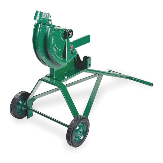
1800
Mechanical Bender
1/2" through 1" Rigid and IMC Conduit
Read and understand all of the instructions and
safety information in this manual before operating
or servicing this tool.
Register this product at www.greenlee.com
99961660
© 2012 Greenlee Textron Inc.
IM 932 REV 11 5/12
Advertisement
Table of Contents

Related Manuals for Greenlee 1800 Mechanical Bender


Summary of Contents for Greenlee 1800 Mechanical Bender
- Page 1 1/2" through 1" Rigid and IMC Conduit Read and understand all of the instructions and safety information in this manual before operating or servicing this tool. Register this product at www.greenlee.com 99961660 © 2012 Greenlee Textron Inc. IM 932 REV 11 5/12...
-
Page 2: Table Of Contents
Keep this manual available to all personnel. Replacement manuals are available upon request at no charge at www.greenlee.com. All specifications are nominal and may change as design improvements occur. Greenlee Textron Inc. shall not be liable for damages resulting from misapplication or misuse of its products. KEEP THIS MANUAL Greenlee / A Textron Company... -
Page 3: Important Safety Information
• Use proper lifting practices when lifting the bender. result in severe injury or death. The bender weighs over 75 lb (34 kg), and requires more than one person to lift. Failure to observe these precautions may result in injury. Do not leave the ratchet handle in the UP position when the bender is not in use. A handle left in the UP position could fall unexpectedly. Use this product for the manufacturer’s intended purpose only. Use other than that which is described in this manual may result in injury or property damage. Greenlee / A Textron Company 4455 Boeing Dr. • Rockford, IL 61109-2988 USA • 815-397-7070... -
Page 4: Setup
6. Remove the conduit from the bender. 7. Lower the handle. Note: Always keep the handle in the DOWN position when not in use. Bending Degree Lever Indicator Unit Handle Pipe Hooks Pipe Supports Figure 1 Greenlee / A Textron Company 4455 Boeing Dr. • Rockford, IL 61109-2988 USA • 815-397-7070... -
Page 5: Illustrated Bending Glossary
9. rise — the distance from the end of a straight section of conduit or pipe to the bend; measured from the end to the center line of the conduit or pipe. Also called stub or stub-up. 10. saddle — a three-bend or four-bend combination; used to avoid an obstruction. 11. shrink — the amount of conduit “lost” when laying out an offset bend working toward an obstruction. 12. springback — the amount, measured in degrees, that a conduit or pipe tends to straighten after being bent. Greenlee / A Textron Company 4455 Boeing Dr. • Rockford, IL 61109-2988 USA • 815-397-7070... -
Page 6: Bending Conduit
Stub Dimensions Table Minimum Minimum Distance Conduit Size Shoe Radius Deduct Stub Length from End of Conduit 1/2" 2-5/8"* 6-1/2" 5-1/2" 3/4" 4-5/8" 9-1/2" 8-1/2" 1" 1" 5-7/8" 12" 11" Figures are approximate * To meet electrical code, bend 1/2" diameter conduit in the 3/4" position to produce a bend with a radius greater than 4". Greenlee / A Textron Company 4455 Boeing Dr. • Rockford, IL 61109-2988 USA • 815-397-7070... - Page 7 Center-to-Center 8" 12" 16" 20" 24" 28" 32" 36" 40" 44" Max Conduit Size 1/2" 1" 45° Center-to-Center 8-1/2" 11-5/16" 14-1/8" 16-15/16" 19-13/16" 22-5/8" 25-7/16" 28-1/4" 31-1/8" Figures are approximate To calculate the center-to-center distance for any other offset bend, multiply: (for 15° bends) Height of the Obstruction x 3.86 (for 30° bends) Height of the Obstruction x 2 (for 45° bends) Height of the Obstruction x 1.4 Greenlee / A Textron Company 4455 Boeing Dr. • Rockford, IL 61109-2988 USA • 815-397-7070...
-
Page 8: Special Bending Information
START OF FIRST BEND LENGTH LENGTH – X HEIGHT ANGLE BENDING BENDING MARK 1 MARK 2 1. Select the size and type of conduit. Measure the height of the obstruction and the distance labeled LENGTH. Determine the angle to be used. 2. Find the chart that corresponds to the size of conduit selected in Step 1. 3. To the right of the size and type of conduit, find the dimension labeled X. Subtract X from LENGTH. Place the first bending mark this distance from the end of the conduit. 4. Under the column labeled ANGLE, find the angle of bend. Find the intersection of the L1 row and the appropriate HEIGHT column. The number at this intersection is the dimension L1. Place the second bending mark L1 inches from the first bending mark. 5. See the Operation section of this manual. Greenlee / A Textron Company 4455 Boeing Dr. • Rockford, IL 61109-2988 USA • 815-397-7070... - Page 9 1. Select the size and type of conduit. Measure the height of the obstruction and the distance labeled LENGTH TO CENTER. Determine the angle to be used. 2. Find the chart that corresponds to the size of conduit selected in Step 1. 3. Under the column labeled ANGLE, find the angle of bend needed. Find the intersection of the Z row and the appropriate HEIGHT column. The number at this intersection is the dimension Z. Subtract Z from the LENGTH TO CENTER. Place the first bending mark here. 4. In the same column, find the row labeled L1. Place the second bending mark L1 inches from the first bending mark. 5. In the same column, find the row labeled L2. Place the third bending mark L2 inches from the second bending mark. 6. See the Operation section of this manual. Note: The second bend angle will be twice the number of degrees as the first and third bends. Greenlee / A Textron Company 4455 Boeing Dr. • Rockford, IL 61109-2988 USA • 815-397-7070...
- Page 10 4. In the same column, find the row labeled L1. Place the second bending mark L1 inches from the first bending mark. 5. In the same column, find the row labeled L2. Add L2 to the STRAIGHT SECTION. Place the third bending mark this distance from the first bending mark. 6. Make the final bending mark L1 inches from the third bending mark. 7. See the Operation section of this manual. U-Bends LENGTH HEIGHT BENDING BENDING MARK 1 MARK 2 1. Select the size and type of conduit. Determine the LENGTH and the HEIGHT. 2. Find the chart that corresponds to the size of conduit selected in Step 1. 3. Under the column labeled ANGLE, find 90°. Find the intersection of the Y row and the HEIGHT column that cor- responds to the dimension labeled LENGTH in the illustration. Place the first bending mark Y inches from the end of the conduit. 4. Find intersection of the L1 row and the HEIGHT column that corresponds to the dimension labeled HEIGHT in the illustration. Place the second bending mark L1 inches from the first mark. 5. See the Operation section of this manual. Greenlee / A Textron Company 4455 Boeing Dr. • Rockford, IL 61109-2988 USA • 815-397-7070...
- Page 11 90.00 1.50 3.50 6.50 9.50 15.50 27.50 90.00 12.94 15.94 21.94 33.94 90.00 20.47 23.47 29.47 41.47 90.00 12.77 12.77 12.77 12.77 MINIMUM H=12.77 *Note: Radius provided has been corrected to include 3% springback. Greenlee / A Textron Company 4455 Boeing Dr. • Rockford, IL 61109-2988 USA • 815-397-7070...
- Page 12 25.14 32.06 MINIMUM H=9.77 90.00 1.00 4.00 7.00 13.00 25.00 90.00 15.40 21.40 33.40 90.00 24.91 30.91 42.91 90.00 16.39 16.39 16.39 MINIMUM H=16.39 *Note: Radius provided has been corrected to include 3% springback. Greenlee / A Textron Company 4455 Boeing Dr. • Rockford, IL 61109-2988 USA • 815-397-7070...
-
Page 13: Illustration
1800 Mechanical Bender Illustration Greenlee / A Textron Company 4455 Boeing Dr. • Rockford, IL 61109-2988 USA • 815-397-7070... -
Page 14: Parts List
4455 Boeing Drive • Rockford, IL 61109-2988 • USA • 815-397-7070 USA Tel: 800-435-0786 Canada Tel: 800-435-0786 International Tel: +1-815-397-7070 An ISO 9001 Company • Fax: 800-451-2632 Fax: 800-524-2853 Fax: +1-815-397-9247 Greenlee Textron Inc. is a subsidiary of Textron Inc. www.greenlee.com...
Need help?
Do you have a question about the 1800 Mechanical Bender and is the answer not in the manual?
Questions and answers