Advertisement
Attention:
Please read all
instructions carefully
before using the
product.
Contents
Safety Information
Components-Parts
Components-Fixings
Assembly Instructions
Parts List
Model:
JX-1600
Retain this
manual for
reference
2017-02-13
OWNER'S
MANUAL
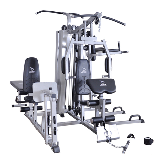
Corporate Multi-Station Gym - 4 station
dual stack with 154lbs each stack
JX-1600
Advertisement

Related Manuals for Force USA JX-1600


Summary of Contents for Force USA JX-1600
- Page 1 Attention: Please read all instructions carefully before using the product. Contents JX-1600 Safety Information Corporate Multi-Station Gym - 4 station dual stack with 154lbs each stack Components-Parts Components-Fixings Assembly Instructions Parts List Model: JX-1600 Retain this manual for reference 2017-02-13 OWNER’S...
-
Page 2: Table Of Contents
Contents Before you Begin Safety Information Components-Fixings Components-Parts Assembly Instructions 6-30 Parts List 31-32... -
Page 3: Before You Begin
Before you Begin Thank you for selecting JX-1600 Six Station Gym. For your safety and benefit, read this manual carefully before using the machine. As a manufacturer, we are committed to provide you complete customer satisfaction. If you have any questions, or find there are missing or damaged parts, we... -
Page 4: Safety Information
Safety Information Important – Please read fully before assembly or use Warning for optimum safety This equipment is built 11. Select an appropriate weight plate to however we still remind you to read the entire exercise according to your physical condition. manual before you assemble or operate the It is recommended in the way of step by step. -
Page 5: Components-Fixings
Components - Fixings M8x18 Allen Bolt x 18 M8x65 Allen Bolt x 8 M6x20 Allen Bolt x 4 M10x45 Allen Bolt x 9 M10x50 Allen Bolt x 9 M10x20 Allen Bolt x 36 M10x85 Allen Bolt x 3 M10x28 Allen Bolt x 1 M10x70 Allen Bolt x 5 M10x65 Allen Bolt x 2 M10x75 Allen Bolt x 1... -
Page 6: Components-Parts
Components - Parts (1) - Page 7 Components - Parts (2)
-
Page 8: Assembly Instructions
Assembly Instructions Tools: Adjustable spanner x 2 Attention: It is strongly recommended to assemble the equipment by two or more people, otherwise it may cause serious injury. The icon indicates the spanner can be directly used to tighten and secure during assembly. - Page 9 Step 1 1. Sequentially put 1 x Rubber Bumper (62), 1 x Shock Spring (61) and 1 x Rubber Bumper (62) through the Guide Rod (2), then insert the Guide Rod (2) into the Main Base Frame (1), and secure with 4 x M10×20mm Allen Bolts (66) and 4 x φ10mm Washers (84).
- Page 10 Step 2 1. Attach 2 x Brackets (42) to the (35) using 4 x M10×70mm Carriage bolts (76) Side Base Support Frame and 4 x M10 Nuts (90). (Note: Do not tighten the Nuts ) 2. Attach the (35) to the Main base frame (1) using 2 x M10×90mm Carriage Side Base Support Frame bolts (77), 2 x φ10mm Washers (84) and 2 x M10 Aircraft Nuts (88).
- Page 11 Step 3 1. Attach the (42) to the Rear Base Support (5) using 2 x M10×70mm Carriage 140x45mm Flat Bracket bolts (76) and 2 x M10 Nuts (90). (Note: Do not tighten the Nuts) 2. Attach the Main Base Support (4) and Rear Base Support (5) to the Main base frame (1) using 2 x M10×90mm Carriage bolts (77), 2 x φ10mm Washers (84) and 2 x M10 Aircraft nuts (88).
- Page 12 Step 4 Disassemble the 4 x M10 Nuts (90) on the Side Base Support Frame (35). 2. Attach the Leg Press Block Frame (45) to the sing 1 x M10×90mm Side Base Support Frame(35) u Carriage Bolts (77), 3 x φ10 Washers (84) and 3 x M10 Aircraft Nuts (88). 3.
- Page 13 The label words on up direction and face outwards Front Step 5 1. Attach the Leg Press Rear Support (48) to the Side Base Support Frame (35) using 1 x Axle Ø16×154×M10 (81), 2 x Ø10mm Washers (84) and 2 x M10×20mm Allen Bolts (66). 2.
- Page 14 Step 6 1. Attach the Sit Up Base Frame (51) to the 2 x M10×20mm Allen Leg Press Backrest Support (38) using Bolts (66), 2 x Ø10mm Washers (84) and 1 x M10×Ø16×57 Axle (82). 2. Attach the Sit Up Board Front Vertical Support (52) to the Sit Up Base Frame (51) using 1 x M10×75mm (72), 2 x Ø10mm Washers (84) and 1 x M10 Aircraft Nuts (88);...
- Page 15 Step 7 1. Disassemble the 2 x M10 Nut (90) from the Rear Base Support (5). 2. Attach the Chin up bar upright support (10) to the Rear Base Support (5) using 2 x φ10mm Washers (84) and 2 x M10 Aircraft Nuts (88). 3.
- Page 16 The direction of weight plate inserting holes The direction of weight plate inserting holes Step 8 1. Put the Guide Rod (2) through the Weight Plates (91), each unit is equipped with 13 pieces of weight plates. 2. Hammer 2 x Weight Stem Guide Sleeves (20) into the Selector Stem (148) respectively, then insert the Selector Rod (7) into the Selector Stem (148), and secure the Selector Rod (7) by screwing 2 x M10×25 Allen Bolts (78) in the Selector Stem (148).
- Page 17 Step 9 Attach the L&R Guide Rod Holder (11&12) to the Guild Rod (2) using 4 x M10×20mm Allen Bolts (66) and 4 x Ø10mm Washers (84). Attach the L&R Guide Rod Holder (11&12) to the Upper frame (9) using 2 x M10×70mm Carriage Bolts (76), 2 x φ10mm Washers (84) and 2 x M10 Aircraft Nuts (88).
- Page 18 Step 10 1. Disassemble the 2 x M10 Nuts (90) from the Main Base Frame (1). 2. Attach the Power Tower Frame (13) to the Main Base Frame (1) using 2 x φ10mm Washers (84) and 2 x M10 Aircraft Nuts (88). 3.
- Page 19 Step 11 1. Attach the L&R Dip Arm (14&15) to the Power Tower Frame (13) using 2 x M10×90mm Carriage Bolts (77), 2 x φ10mm Washers (84) and 2 x M10 Aircraft Nuts (88). 2. Insert 2 x VKR Handle (33) into the L&R Dip Arm (14&15) respectively and secure with 2 x M10×20mm Allen Bolts (66) and 2 x Ø10mm Washers (84).
- Page 20 Step 12 1. Connect the Front Press Frame (16) to the Upper Frame (9) using Φ16×154×M10 Axle (81), and secure with 2 x M10×20mm Allen Bolts (66) and 2 x Ø10mm Washers (84), then attach 2 x ø50×2 End Caps (134) to the Front Press Frame (16). 2.
- Page 21 Step 13 1. Attach the L&R Butterfly Frame (17&18) to the Front Press Frame (16), and secure with 2 x 36×27×M18 Lock Nut (133), 2 x ø10mm Washers (84) and 2 x M10×20mm Allen Bolts (66). 2. Attach the two Butterfly Pads (158) to L&R Butterfly Frame (17&18) using 4 x M8×65mm Allen Bolts (65), 4 x ø8mm Washers (85).
- Page 22 Step 14 1. Put the two Push Up Handles (56) through the Left and Right Push Up Tube (54&55) respectively, and secure with 2 x M10×20mm Allen Bolts (66) and 2 x ø10mm Washers (84). 2. Connect the Left and Right Push Up Tube (54&55) and U-shaped Bracket (3) to the Push up base Support (53), and secure with 2 xM10×70 Carriage Bolts (76), 2 x ø10mm Washers (84) and 2 x M10 Aircraft Nuts (88).
- Page 23 Step 15 1. Attach the two Arm Curl Pads (157) to the L&R Dip Arm (14&15) using 2 x M8×65mm Allen Bolts (65) and 2 x ø8mm Washers (85) respectively. Attach the Small Backrest Pad (156) to the Power Tower Frame (13) using 2 x M8×70mm Allen Bolts (87) and 2 x ø8mm Washers (85).
- Page 24 Right Left Step 16 1. Attach the L&R 10×70mm Carriage Side Handle (40&41) to the Leg Press Seat Pad (39) using 2 x M Bolts (76) , 2 x ø10mm Washers (84) and 2 x M10 Aircraft Nuts (88). 2. Connect the Foot Press Inner Adjustable Tube (50) to the Foot Plate (49) using 1 x M10×80mm Allen Bolt (73), 2 x ø10 Washers (84) and 1 x M10 Aircraft Nut (88).
- Page 25 CABLE LOOP DIAGRAM (Upper Cable) Step 17 1. Find out the end with threaded head of the Upper Cable (149-1) as shown in the diagram, thread the end in sequence through the gap between the Upper Frame (9) and the Front press frame (16), the upper long notch of the Front vertical frame (8), the rear long notch of the Upper Frame (9), the round hole of the Left Guide Rod Holder (11) and finally screw it into the Selector Rod (7).
- Page 26 Step 18 1. Find out the Butterfly Cable (149-2) as shown in the diagram, and then hang the two ends of the butterfly cable on the hooks of the Left and Right Butterfly Frame (17&18). Connect the Pulley (123) A, B, C and the Upper Cable (149-1) to the Cross Double Floating Pulley Bracket (59) using 1 x M10×45mm Allen Bolt (67), 1 x ø10mm Washer (84), 1 x M10 Aircraft Nut (88) and 2 x Butterfly Pulley Brackets (60), and ensure the cable in the pulley groove.
- Page 27 CABLE LOOP DIAGRAM ( Lower Cable ) Step 19 1. Find out the end without plastic ball head of the Lower Cable (149-3) as shown in the diagram, thread the end in sequence through the long notch of the Leg Developer (23) and Seat support frame (21), and finally connect the end to the U-shape bracket of the Main Base Support (4) using 1 x M10×28mm (69), 2 x ø10mm Washers (84) and 1 x M10 Aircraft Nut (88).
- Page 28 CABLE LOOP DIAGRAM ( Leg Press Diagram ) Step 20 1. Find out the end with thread head of the Leg Press Cable 1 (149-4) as shown in the diagram, screw the end to the Selector rod (7). Thread another end through the round hole and long notch of the Right Guide Rod Holder (12).
- Page 29 Step 21 1. Attach the Backrest Pad (152) to the 4 x M8×18mm Allen Bolts Leg Press Backrest Support (38) using (64) and 4 x ø8mm Washers (85). Attach the Seat Pad (153) to the 4 x M8×18mm Allen Bolts (64) and 4 x Leg Press Seat Pad (39) using ø8mm Washers (85).
- Page 30 Step 22 Attach the Weight Stack Cover (6) to the Main Base Frame (1) and L&R Guide Rod Holder (11&12) using 8 x M10×20mm Allen Bolts (66) and 8 x ø10mm Washers (84).
- Page 31 Step 23 1. Attach the Backrest Pad (152) to the Front vertical frame (8) using 4 x M8×18mm Allen Bolts (64) and 4 x ø8mm Washers (85). 2. Attach the Seat Pad (153) to the Slant Support (22) using 4 x M8×18mm Allen Bolts (64) and 4 x ø8mm Washers (85).
- Page 32 Step 24 1. Connect the Lat Bar (28) to the Upper Cable (149-1) using 1 x 15 Joints Chain (130) and 2 x Gourd Hook (132), hang the Lat Bar (28) on the Upper Frame (9) when not using to avoid injury. 2.
-
Page 33: Parts List
Parts List Part # Description Part # Description Main Base Frame 120x45mm Flat Bracket Guide Rod 51.5x51.5mm U-shaped Bracket 140x51.5mm U-shaped Bracket Leg Press Block Frame Main Base Support Leg Press Front Support Rear Base Support Leg press outer adjust tube Weight Stack Cover Leg Press Rear Support Selector rod /13 Holes... - Page 34 Part # Description Part # Description φ8 Washer M8 Lock Knob φ6 Washer Pin φ10×85×M8 M8×70 Allen Bolt Ankle Strap M10 Aircraft Nut Chain 15 joints M12 Aircraft Nut Chain 8 joints M10 Nut Gourd Hook 5KG Steel Weight Plate 36×27×M18 Lock Nut Foot φ50 End Cap φ50×2...
Need help?
Do you have a question about the JX-1600 and is the answer not in the manual?
Questions and answers