
Subscribe to Our Youtube Channel
Related Manuals for Force USA JX-DS926


Summary of Contents for Force USA JX-DS926
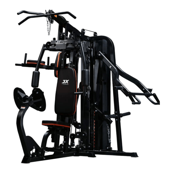
- Page 1 JX-DS926 OWNER’S MANUAL Multi-Utility 205lb Home Gym with Lever- Press and FID Utility Bench Included CAUTION! Read all precautions and instructions in this manual before using this equipment.
-
Page 2: Safety Information
、 Safety information Important – Please read fully before assembly or use This exercise equipment is built for optimum safety. However, certain precautions apply whenever you operate a piece of exercise equipment. Be sure to read the entire manual before you assemble, operate or use this equipment. - Page 3 Components - Parts Please check you have all parts listed below Note: Some of the smaller components may be pre-fitted to larger components. Please check carefully before contacting us regarding any missing components.
- Page 8 Components - Fixings Please check you have all parts listed below Note: The quantities below are the correct amount to complete the assembly. In some cases more hardware may be supplied than are required. Some of the fixings are pre-fitted to the larger components. Please check carefully before contacting us regarding any missing fixings.
- Page 9 Assembly Instructions Step 1 Insert 2 pcs guide rods (6#) into the holes of the Rear Stabilizer(2#) separately and tighten them with 2 pcs M10*20 Allen Bolt(99#) and 2pcs φ10 washers(110#). Slide the 2pcs rubber bumper(81#) along the guide rods (6#) separately. Attach the Main base Frame(1#) to the Rear Stabilizer(2#) as the diagram shows and tighten them with 2pcs M10*70 carriage bolt(91#),1pc bracket(61#),2pcs φ10 washers(110#) and 2pcs M10 Aircraft nuts(109#) .
- Page 10 Assembly Instructions Step 2 Attach the front vertical frame(5#) onto the base frame(1#). Carefully align the holes and secure them with 2pcs M10*70 carriage bolt(91#), 1 pc bracket(58#),2pcs φ10 washers(110#) and 2pcs M10 Aircraft nuts(109#) .
- Page 11 Assembly Instructions Step 3 A.Place the long bend frame(9#) onto the right stabilizer (3#), Carefully align the holes and secure it with 2pcs M10*70 carriage bolt(91#), 1 pc bracket(58#),2pcs φ10 washers(110#) and 2pcs M10 Aircraft nuts(109#) . B.Place the shorter support(39#) onto the right stabilizer(3#), Secure it with the same way in A. C.Place the lower vertical frame(11#) onto the left stabilizer(4#),Secure it with the same way in A.
- Page 12 Assembly Instructions Step 4 Place 13pcs weight plate(64#) along the guide rods(6#) from the top to the bottom, Insert the Selector Rod(40#) into the center hole of the weight plates. And then place the weight stem(63#) again. Select the desired weight with the selector pin(77#) during the exercising.
- Page 13 Assembly Instructions Step 5 A.Place the Upper Frame(7#) onto the Front Vertical Frame(5#), Align the holes and secure them with 2pcs M10*90 carriage bolt(90#), 1 pc bracket(58#),2pcs φ10 washers(110#) and 2pcs M10 Aircraft nuts(109#) . B.Attach the 2pcs Fixing frame (8#) to the end of the upper frame (7#) as the diagram shows,Secure them with 2pcs M10*70 carriage bolt(91#),2pcs φ10 washers(110#) and 2pcs M10 Aircraft nuts(109#) .
- Page 14 Assembly Instructions Step 6 A.Attach the upper bend frame (12#)into the lower frame(11#),Secure them together with 2pcs M10*90 carriage bolt(90#), 2 pc bracket(55#),2pcs φ10 washers(110#) and 2pcs M10 Aircraft nuts(109#) . B.Place the connection frame(10#) between the upper frame(12#) and upper frame(7#), Secure them together with 4pcs M10*70 carriage bolt(91#),4pcs φ10 washers(110#) and 4pcs M10 Aircraft nuts(109#) ,1pc bracket(56#) as the diagram shows.
- Page 15 Assembly Instructions Step 7 A. Attach the foot support(44#) to the lower frame (11#) and secure them together with 2pcs M10*70 Carriage bolt (91#),1 pc bracket(58#),2pcs φ10 washer(110#) and 2pcs M10 Aircraft nuts(109#) . B.Attach the left & right dip support(13#&14#) to the lower frame (11#), Secure them with 1pc M12*95 Hex bolt (89#),2pcs φ12 washers(108#),1pc M12 Aircraft nut(107#).4pcs M8*10 Allen bolt (105#),4pcs φ8 washer (112#)1 pc 4-hole bracket(15#).
- Page 16 Assembly Instructions Step 8 A.Attach the 2pcs weight plate holders(35#) to the Long bend frame (9#),Secure them with 2pcs M10*90 carriage bolt (90#),2pcs φ10 washer(110#) and 2pcs M10 Aircraft nuts(109#) . B.Attach the 2pcs long sleeve(160#) to the weight place holders(35#),and then attach attach the 2pcs collar(86#) again as the diagram shows.
- Page 17 Assembly Instructions Step 9 Attach the connection frame (38#) to the shorter support(39#) and secure them with 1pc axle(51#),2pcs φ10 washer(110#),2pcs M10 aircraft nut(109#). Insert the inner frame(37#) into the adjustment frame(36#) and select the height with the lock knob (71#).
- Page 18 Assembly Instructions Step 10 Attach the weight plate holder(23#) to the lifting arm(34#) ,and secure them together with 1pc M10*20 Allen bolt (99#) and 1pcs φ10 washer(110#) . Attach the sleeve(157#) to the weight plate holder(23#) and then attach the collar (86#). Repeat the same way to install another one.
- Page 19 Assembly Instructions Step 11 Attach the Front Press Frame(18#) to the Upper Frame(7#), Secure them with 1pcs axle(59#),2pcs φ 10 washer(110#)and 2pcs M10 Aircraft nut (109#). Attach the swivel pulley bracket(53#) to the front vertical frame (5#), secure them with 1pc M10X65 Allen bolt(94#),2pcs φ10 washers(110#)and 2pc M10 Aircraft nuts(109#) .Repeat the same way to install another swivel pulley bracket.
- Page 20 Assembly Instructions Step 12 Attach the plastic cover (74#) as the diagram shows,Attach the right butterfly adjustment frame (20#) through the hole of the front press base (18#),Secure it with 1 pc lock ring(76#),1pc φ10 washer (110#)and M10*16 Allen bolt(100#). Attach the right butterfly frame(22#) to the right butterfly adjustment frame(20#) as the diagram shows, and secure them with 1pc M8*22 Allen bolt(103#),1 pc φ8 washer (112#),1pc plastic washer(114#), 1pc M8 aircraft nut(111#).1pc spacer(75#),1pcφ10 washer(110#)and 1pc M10*20 Allen bolt(99#).
- Page 21 Assembly Instructions Step 13 Attach the front support frame(31#) to the front vertical frame (5#)and secure them together with 2pcs M10*90 Carriage bolt(90#),1 pc bracket(55#),2pcsφ10 washer(110#)and 1pc M10 Aircraft nut(109#). Attach the left frame(32#)to the end of the front support frame(31#),Secure it with M24*1.5 Lock nut(113#) with the special tool shown above.
- Page 22 Assembly Instructions Step 14 Attach one end of the seat pad support(24#) to the front vertical frame (5#) , secure them together with 2pcs M10*90 carriage bolt(90#),1 pc bracket(55#),2pcsφ10 washer(110#)and 2pcs M10 Aircraft nut(109#). Attach another end of seat pad support (24#) to the base frame(1#),and secure them with 1pcM10*90 carriage bolt(90#),1pcφ10 washer(110#)and 1pc M10 Aircraft nut(109#).
- Page 23 Assembly Instructions Step 15 Attach the leg press support frame(25#) to the end of main base frame(1#), secure them with 1pc axle (52#) ,2pcsφ10 washer(110#)and 2pcs M10*20 Allen bolt(99#). Attach the leg press connection frame(27#) into the leg press support frame(25#),Secure it with 1pc lock knob(71#).
- Page 24 Assembly Instructions...
- Page 25 Step 16 Important: Study and follow the diagram carefully. A Attach the 4400 mm Upper cable (131#) through the opening of the upper frame (7#), Make sure the ball stopper should be in front of the upper frame, Place 1PC Pulley (162#) below the cable and secure the 1 pulley using 1PC M10 ×...
- Page 26 Assembly Instructions...
- Page 27 Step 17 A Attach the 1740MM abdominal cable(135#) through the opening of the front vertical frame(5#) as the diagram shows,Make sure the ball stopper should be in front of the front vertical frame.Place the 1 pulley below the cable,and secure it with 1pc M10*70 Allen bolt (93#),2PC ø10 washer (110#) and 1× M10 Aircraft nut (109#).
- Page 28 Assembly Instructions...
- Page 29 Step 18 Important: Study and follow the diagram carefully. A Attach the end of the 3120 MM butterfly cable(132#) to the hook . B. place the pulley below the cable , Secure the pulley to the swivel pulley bracket(53#) with 1PC M10X50 Allen bolt (95#),2pcs φ10 washer (110#) and 1pcM10 Aircraft nut (109#).
- Page 30 Assembly Instructions...
- Page 31 Step 19 A. Attach the end of the 1030MM leg press cable (133#) to the hook as the diagram shows. Draw the cable downwards and place 1pc pulley onto the cable,Secure it with 1PC M10X50 Allen bolt (95#),2pcs φ10 washer (110#) and 1pcM10 Aircraft nut (109#). B.C.Draw the cable around the cable and backwards, Place 2pcs pulley below and onto the cable, Secure them with 1PC M10X70 Allen bolt (93#),4pcs φ10 washer (110#) and 2pcM10 Aircraft nut (109#).
- Page 32 Assembly Instructions...
- Page 33 Step 20 A.Attach the end of 3800MM push cable(136#) to the hook as the diagram shows,Secure it with 1PC M10X28 Allen bolt (98#),2pcs φ10 washer (110#) and 1pc M10 Aircraft nut (109#). Place 1 pc pulley (80#) below the cable, Secure it with 1PC M10X50 Allen bolt (95#),2pcs φ10 washer (110#) and 1pc M10 Aircraft nut (109#).
- Page 34 Assembly Instructions...
- Page 35 Step 21 A.Attach the 4800MM pecfly cable(134#) through the opening of the pecfly pulley bracket (46#)as the diagram shows,Make sure that the ball stopper should be in front of it.Place 1 pc pulley below the cable, Secure it with 1PC M10X50 Allen bolt (95#),2pcs φ10 washer (110#) and 1pc M10 Aircraft nut (109#). B.Draw the cable around the pulley and downwards,place 1pc pulley (80#) onto the cable, secure it with the 1PC M10X45 Allen bolt (96#),2pcs φ10 washer (110#) and 1pc M10 Aircraft nut (109#).
- Page 36 Assembly Instructions Step 22 Attach 1pc weight stack cover (48#) and secure it with 6pcs M10*16 Allen bolt(100#),6pcs φ10 washer (110#) as the diagram shows. Repeat the same way to install another weight stack cover.
- Page 37 Assembly Instructions Step 23 A Attach the seat pad(67#) and pad adjustment frame(43#) ,secure it with 4pcsM8*18 Allen bolt (104#) and 4pcs φ8 washer (112#). B.Attach the backrest pad adjustment frame(43#) into the hole of the front vertical frame (5#), Select the desired place with the lock knob(71#).Attach the backrest pad(66#)to the backrest pad adjustment frame (43#)and secure it with 2pcs M8*18 Allen bolt(104#) and 2pcsφ8 washer (112#).
- Page 38 Assembly Instructions Step 24 A Attach the backrest pad(68#) and secure it with 2pcs M8*75 Allen bolt (101#) and 2pcs φ8 washer (112#). B.Attach the 2pcs arm pad (69#) onto the left & right dip arm(13#&14#) and secure it with4pcs M8*65 Allen bolt(102#) and 4pcsφ8 washer (112#).
- Page 39 Assembly Instructions Step 25 A Attach the Lat bar(29#) to the end of the upper cable (131#)with 2pcs 7# gourd hook(82#) and 1pc 15-Joint Chain(83#). B.Attach the tricep rope(163#) to the end of the abdominal cable(135#) with 1pc 7# gourd hook. C.
- Page 40 Workout Area The free area must be at least 0.6m greater than the training area. This is a space where you can safely dismount, without obstruction, in case of an emergency. Where two pieces of equipment are positioned adjacent to each other the free area may be shared. Only one person should be within the training area when the equipment is in use.
- Page 41 Exercise Information Before starting Tailor your exercise program according to your physical condition. If you have been inactive for several years, or are overweight, you must start slowly and increase your time on the equipment; a few minutes per workout increase is advisable. Initially, you may be able to exercise only for a few minutes in your target zone, however, your aerobic fitness will improve over the next six to eight weeks.
- Page 42 Exercise Information Muscle Chart Aerobic Exercise Aerobic exercise improves the fitness of your lungs and heart - your body’s most important muscle. Aerobic exercise is promoted by any activity that uses your large muscles (arms, legs, or buttock, for example). Weight Training Along with aerobic exercising which helps get rid of and keep off the excess fat that our bodies can store, weight training is an essential part of an exercise routine.
- Page 43 Exercise Information Warming up and Cooling down Each workout should include the following three parts: 1. A warm-up, consisting of 5 to 10 minutes of stretching and light exercise. A proper warm-up increases your body temperature, heart rate, and circulation in preparation for exercise. 2.
- Page 44 Exercise Information Calf/Achilles stretch With one leg in front of the other, reach forward and place your hands against a wall. Keep your back leg straight and your back foot flat on the floor. Bend your front leg, lean forward and move your hips toward the wall.
- Page 45 Exercise Information Using the Home Gym Important: When working out, do the following for each exercise: exhale while exerting/lifting and inhale while returning to starting position in a slow and controlled manner. Read all caution and warning stickers before using this equipment. ...
-
Page 46: Care And Maintenance
Care and Maintenance Replace defective The safety level of the Do not attempt to repair components immediately equipment can only be this equipment yourself. and/or keep the equipment out maintained if it is examined Should you have any difficulty of use until repair. regularly for damage and wear with assembly, operation or Pay special attention to... -
Page 47: Parts List
Parts List Part # Description QTY Part # Description Main base frame pecfly pulley bracket Rear stabilizer swivel bracket right stabilizer weight stack cover left stabilizer weight stack cover bracket front vertical frame axle guide rod axle Upper frame axle Fixing frame swivel pulley bracket Long bend frame... - Page 48 Part # Description QTY Part # Description M10*70 Carriage bolt 4400 upper cble M10×85 Allen bolt 3120 butterfly cable M10×70 Allen bolt 1030 leg press cable M10×65 Allen bolt 4800 fecfly cable M10×50 Allen bolt 1740 abdominal cable M10×45 Allen bolt 3800 adjustment cable M10×35 Allen bolt 25×50×1.5 End cap...
- Page 49 φ8×70 handle grip 50×170 anti slip 50×190 anti slip small rubber bumper φ10 big washer End cap...
Need help?
Do you have a question about the JX-DS926 and is the answer not in the manual?
Questions and answers