Table of Contents
Advertisement
Advertisement
Table of Contents

Related Manuals for Sonel MIC-10


Summary of Contents for Sonel MIC-10
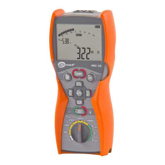
- Page 3 OPERATING MANUAL INSULATION RESISTANCE METER MIC-10 SONEL Test & Measurement Santa Clara, Ca. USA SONEL SA Świdnica, Poland Version 1.1 17/03/2017...
- Page 4 Thank you for purchasing the MIC-10 insulation tester. Please acquaint yourself with this manual to avoid measuring errors and prevent possible problems related to the operation of the meter. This device complies with part 15 of the FCC Rules. Operation is subject to the following two conditions: (1) This device may not cause harmful interference, and (2) this device must accept any interference received, including interference that may cause undesired operation.
-
Page 5: Table Of Contents
Additional uncertainties according to IEC 61557-2 (R ) ......22 8.2.2 Additional uncertainties according to IEC 61557-4 (R 200mA) ... 22 CONT EQUIPMENT ......................23 ..................23 TANDARD EQUIPMENT ..................23 PTIONAL ACCESSORIES MANUFACTURER ....................24 OPERATING MANUAL MIC-10 version 1.1... - Page 6 OPERATING MANUAL MIC-10 version 1.1...
-
Page 7: Safety
1 Safety The MIC-10 meter is designed to determine the safety of electrical wiring, to ensure adequate protection against electric shock. For correct operation and accurate results observe the following recommendations: Before operating the meter acquaint yourself thoroughly with this manual. Observe the safety cautions, warnings, and instructions. -
Page 8: Meter Configuration
Selection Beep Auto- signalling Parameter power pressed supply push-button source Symbol(s) Press ENTER to save the selection. The meter then goes into the measurement mode. Press ESC to go the measurement mose without saving changes. OPERATING MANUAL MIC-10 version 1.1... -
Page 9: Measurements
Set the rotary function switch at one of R positions. Each position is marked with the measuring voltage. Connect the test leads according to this diagram. OPERATING MANUAL MIC-10 version 1.1... - Page 10 To cancel the measurement press ESC or START. View of the screen during measurement. View the results after the measurement is completed. Use the button to read the capacitance of the tested object. OPERATING MANUAL MIC-10 version 1.1...
- Page 11 For example, to measure the inter-winding resistance of a small motor, connect the G termianl of the meter with the motor housing: Notes: Danger! During measurements of insulation resistance up to 1 kV occurs at the ends of test leads when connected to the MIC-10 meter. OPERATING MANUAL MIC-10 version 1.1...
- Page 12 1000V, and make it impossible to discharge the object under test. If obeyed the MIC-10 safely discharges the object under test.
-
Page 13: Low-Voltage Measurement Of Resistance
3.2 Low-voltage measurement of resistance 3.2.1 Measurement of resistance of protective conductors and equipotential bonding with 200 mA current NOTE bidirectionally (±200mA). The MIC-10 meter measures R CONT Set the rotary function switch to the R position. CONT The meter is ready for measurement. - Page 14 The measurement results may be affected by additional uncertaintuies. The tested object is live. The measurement is + red LED, + two- cancelled. tone beep Compensation for the test leads resistance is included in the result. OPERATING MANUAL MIC-10 version 1.1...
-
Page 15: Measurement Of Resistance
3.2.2 Measurement of resistance Set the rotary function switch to the R position. The meter is ready for measurement. Connect the meter to the object to be tested as in the following diagram: The measurement is performed continuously. OPERATING MANUAL MIC-10 version 1.1... -
Page 16: Compensation Of Test Leads Resistance
To eliminate the effect of the resistances of the test leads upon the measurements R and R CONT perform the auto-zeroing function as follows: Set the rotary function switch at the R position. ZERO Short the test leads together. Press START. OPERATING MANUAL MIC-10 version 1.1... -
Page 17: Voltage Measurement
The messages disappear, and is displayed. 3.3 Voltage measurement Set the rotary function switch at the V position. Connect the meter to a voltage source. OPERATING MANUAL MIC-10 version 1.1... -
Page 18: Remembering The Last Measurement Result
(by pressing ESC button), to recall the last result press ENTER. The latest measurement result can also be viewed after turning the meter off and then turning on, providing the position of the function selector has not been changed. OPERATING MANUAL MIC-10 version 1.1... -
Page 19: Power Supply Of The Meter
The meter switches off automatically. 4.2 Replacing battery/rechargeable batteries MIC-10 Meters are powered by four AA alkaline LR6 batteries or NiMH rechargeable batteries. NOTE! Before removing the battery cover disconnect the test leads. To replace the batteries: 1. Disconnect the leads from the measuring circuit and turn off the meter 2. -
Page 20: General Principles Regarding Using Nimh Rechargeable Batteries
Do not charge or use batteries in extreme temperatures. Extreme temperatures reduce the lifetime of batteries. Avoid using devices powered from Ni-MH batteries in very hot environments. The nominal working temperature must be observed. OPERATING MANUAL MIC-10 version 1.1... -
Page 21: Cleaning And Maintenance
Before the equipment is sent to a collection point do not dismantle or disassemble any elements. Observe local regulations concerning the disposal of equipment, and depleted batteries. OPERATING MANUAL MIC-10 version 1.1... -
Page 22: Technical Specifications
0.0 to 999.9 k 0.1 k 1.000 to 9.999 M 0.001 M (3 % m.v. + 8 digits) 10.00 to 99.99 M 0.01 M 100.0 to 999.0 M 0.1 M 1.000 to 2.000 G 0.001 G OPERATING MANUAL MIC-10 version 1.1... - Page 23 20.0 to 199.9 0.1 200 to 1999 1 (4% m.v. + 3 digits) Voltage at open terminals: <8 V Output current at R < 2 : I > 200 mA OPERATING MANUAL MIC-10 version 1.1...
-
Page 24: Additional Data
Temperature 0 to 35°C / 32 to 95°F 8.2.2 Additional uncertainties according to IEC 61557-4 (R 200mA) CONT Significant parameter Designation Additional uncertainty Position Supply voltage 0% (BATT is not displayed) Temperature 0 to 35°C / 32 to 95°F OPERATING MANUAL MIC-10 version 1.1... -
Page 25: Equipment
strap for carrying the meter – WAPOZSZE4, plastic hook (to hang the meter) – WAPOZUCH1. 9.2 Optional accessories The following items can be purchased from Sonel or an authorized Sonel distributor: WAPRZ1X2BUBB WAKROBU20K02 crocodile clip CAT III 1000 V blue 1.2 m cable CAT III 1000 V blue... -
Page 26: Manufacturer
Web: www.soneltest.com SONEL S. A. 58-100 Świdnica Poland tel. +48 74 858 38 60 fax +48 74 858 38 09 E-mail: export@sonel.pl Web page: www.sonel.pl NOTE Service repairs must be performed solely by the manufacturer. OPERATING MANUAL MIC-10 version 1.1...
Need help?
Do you have a question about the MIC-10 and is the answer not in the manual?
Questions and answers