Sonel MIC-30 Operating Manual
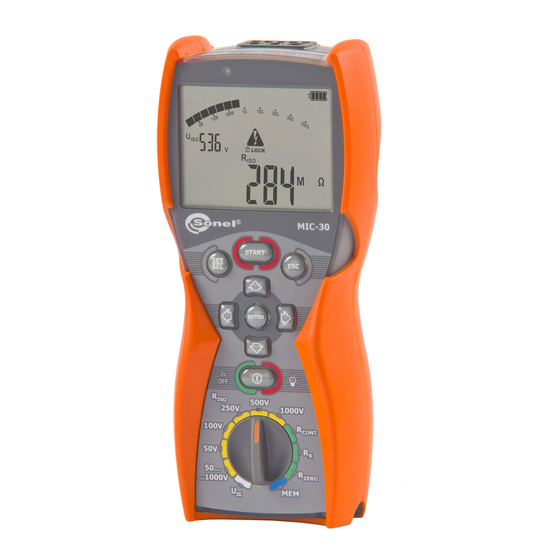
Insulation resistance meter
Hide thumbs
Also See for MIC-30:
- Operating manual (28 pages) ,
- User manual (40 pages) ,
- User manual (40 pages)
Table of Contents
Advertisement
Quick Links
Download this manual
See also:
User Manual
Advertisement
Table of Contents

Related Manuals for Sonel MIC-30


Summary of Contents for Sonel MIC-30
-
Page 1: Operating Manual
OPERATING MANUAL INSULATION RESISTANCE METER MIC-30 SONEL Test & Measurement, Inc. Santa Clara, Ca. USA SONEL SA Świdnica, Poland Version 1.1 22/03/2017... - Page 2 +1 408 898 2215 CAUTION: Equipment changes or modifications not expressly approved by SONEL TEST & MEASUREMENT Inc., the party responsible for FCC compliance, could void the user’s authority to operate the equipment, and could create a hazardous condition.
-
Page 3: Table Of Contents
CLEANING AND MAINTENANCE ..............29 STORAGE ......................29 DISMANTLING AND DISPOSAL ..............30 TECHNICAL SPECIFICATIONS ............... 30 11.1 ......................30 ASIC DATA 11.2 ....................33 DDITIONAL DATA 11.2.1 Additional uncertainties according to IEC 61557-2 (R ) ......33 OPERATING MANUAL MIC-30 version 1.1... - Page 4 11.2.2 Additional uncertainties according to IEC 61557-4 (R 200mA) ... 33 CONT EQUIPMENT ......................34 12.1 ..................34 TANDARD EQUIPMENT 12.2 ..................34 PTIONAL ACCESSORIES MANUFACTURER ....................35 OPERATING MANUAL MIC-30 version 1.1...
-
Page 5: Safety
1 Safety The MIC-30 meter is designed to determine the safety of electrical wiring by measuring insulation resistance to ensure adequate protection against electric shock. For correct operation and accurate results observe the following recommendations: Before operating the meter acquaint yourself thoroughly with this manual. Observe the safety cautions, warnings, and instructions. -
Page 6: Meter Configuration
Change PIN WS-04 power coefficients pressed update adapter supply push-button source Symbol(s) Press ENTER to save the selection. The meter then goes into the measurement mode. Press ESC to go the measurement mode without saving changes. OPERATING MANUAL MIC-30 version 1.1... -
Page 7: Measurements
Press the SET/SEL button to select the three times for calculating the absorption coefficients - t1, t2, t3. Use the buttons to change the settings of t1, t2, t3. Use the buttons to change the values of t1, t2, t3. OPERATING MANUAL MIC-30 version 1.1... - Page 8 The end of the shielded cable has two banana plugs. These two banana plugs may be connected only to the meter. Do not connect either of the banana plugs to the tested object or to the network. Refer to the diagram above. OPERATING MANUAL MIC-30 version 1.1...
- Page 9 ESC or START. View of the screen during measurement. Pressing the SET/SEL button and START simultaneously displays the leakage current I instead of measurement voltage V View the results after the measurement is completed. OPERATING MANUAL MIC-30 version 1.1...
- Page 10 Notes: Danger! During measurements of insulation resistance a high voltage of up to 1 kV occurs at the ends of test leads when connected to the MIC-30 meter. Danger! Do not disconnect test leads before the measurement process is entirely completed.
-
Page 11: Three-Lead Measurement (With A Shielded Lead)
A three-lead measurement technique is used to eliminate the influence of surface currents. For example, to measure the inter-winding resistance of a small motor, connect the G socket of the meter with the motor housing as in the following diagram: OPERATING MANUAL MIC-30 version 1.1... -
Page 12: Measurements With Ws-04 Adapter
Connect the WS-04 plug to the wall socket conductor to be tested. Press and hold START button. The measurement is performed continuously until the START button is released or the pre- set time is reached. OPERATING MANUAL MIC-30 version 1.1... -
Page 13: Low-Voltage Measurement Of Resistance
3.2 Low-voltage measurement of resistance 3.2.1 Measurement of resistance of protective conductors and equipotential bonding with 200 mA current NOTE bidirectionally (±200mA). The MIC-30 meter measures R CONT OPERATING MANUAL MIC-30 version 1.1... - Page 14 Connect the meter to the object tested as in the following diagram: The measurement starts automatically when the meter detects a resistance within the measurement range. The measurement may be also triggered manually by pressing the START button. OPERATING MANUAL MIC-30 version 1.1...
-
Page 15: Measurement Of Resistance
+ red LED, + two- cancelled. tone beep Compensation for the test leads resistance is included in the result. 3.2.2 Measurement of resistance Set the rotary function switch to the position. The meter is ready for measurement. OPERATING MANUAL MIC-30 version 1.1... -
Page 16: Compensation Of Test Leads Resistance
3.2.3 Compensation of test leads resistance To eliminate the effect of the resistances of the test leads upon the measurements R and R CONT perform the auto-zeroing function as follows: Set the rotary function switch at the R position. ZERO OPERATING MANUAL MIC-30 version 1.1... -
Page 17: Voltage Measurement
To remove the compensation for test leads resistances, and return to default calibration, perform the auto-zeroing function with the test leads open. The messages disappear, and is displayed. 3.3 Voltage measurement Set the rotary function switch at the V position. OPERATING MANUAL MIC-30 version 1.1... -
Page 18: Remembering The Last Measurement Result
(by pressing ESC button), to recall the last result press ENTER. The latest measurement result can also be viewed after turning the meter off and then turning on, providing the position of the function selector has not been changed. OPERATING MANUAL MIC-30 version 1.1... -
Page 19: Memory Of Measurement Result Data
4 Memory of measurement result data MIC-30 meters are equipped with memory for storing test results. The memory is organized into 10 memory banks with 99 cells in each bank. Each measurement result can be stored in a numbered memory cell in a selected memory bank. Each cell may contain the entire set of measurements of R and R . - Page 20 To change the cell or bank number use the SET/SEL button to select other cells or banks. Use the buttons to change the number of a cell or bank. OPERATING MANUAL MIC-30 version 1.1...
- Page 21 All data for the main result and supplementary results for a measuring function and the preset measurement settings, and conditions are stored in the memory (e.g. Results of R obtained by the double-lead method and by using WS-04 adapter cannot be saved in the same cell. OPERATING MANUAL MIC-30 version 1.1...
-
Page 22: Viewing Memory Data
This applies to all R and I measurements. 4.3 Deleting memory data The entire memory or individual banks can be deleted. 4.3.1 Deleting bank data Set the rotary switch of function selection at MEM position. OPERATING MANUAL MIC-30 version 1.1... - Page 23 “--”. The symbol appears. Press ENTER. appear asking to confirm deletion. Press ENTER again. After deleting the bank the meter beeps three times and sets the cell number to "01". OPERATING MANUAL MIC-30 version 1.1...
-
Page 24: Deleting The Whole Memory
4.3.2 Deleting the whole memory Set the rotary function switch to the MEM position. Toggle the SET/SEL button until the bank number flashes. Use button to change the bank number to “--”. The symbol appears. Press ENTER . OPERATING MANUAL MIC-30 version 1.1... -
Page 25: Wireless Data Transmission
5 Wireless data transmission 5.1 Computer connection accessories To communicate with a computer the OR-1 wireless module and Sonel Reader PC software is required. It allows users to read and display the measurement data stored in the meter memory. This... - Page 26 During the process of pairing the meter with a PC enter PIN code compatible with the PIN code of the meter defined in main settings. On the computer start data storing programme. Press ESC to exit data transmission mode. Notes: Standard pin for Bluetooth is "1234". OPERATING MANUAL MIC-30 version 1.1...
-
Page 27: Firmware Updates
- at that time all buttons are inactive. After the update completes the meter automatically switches off. Upon switching on the meter briefly displays the current version # of the meter’s firmware. OPERATING MANUAL MIC-30 version 1.1... -
Page 28: Power Supply Of The Meter
If the meter displays ErrX (X – error code) turn the meter off and then on. Incomplete updates are deleted and the meter operates on the previous firmware. If another update attempt does not complete successfully the meter should be returned to Sonel for service, or an authorized service center. -
Page 29: General Principles Regarding Using Nimh Rechargeable Batteries
Disconnect all the test leads from the meter Clean the meter and all its accessories thoroughly Wind the long test leads onto the reels To prevent a total discharge of the batteries charge them periodically. OPERATING MANUAL MIC-30 version 1.1... -
Page 30: Dismantling And Disposal
(3 % m.v. + 8 digits), 1.000 to 9.999 M 0.001M [ (5 % m.v. + 8 digits)] * 10.00 to 99.99M 0.01 M 100.0 to 500.0 M 0.1 M * - for WS-04 adapter OPERATING MANUAL MIC-30 version 1.1... - Page 31 Calculated basing on mA, μA, nA 0 to I Lmax resistance measurements – maximum current at short circuit of leads, Lmax resolution and units result from the measurement range of individual insulation resistance. OPERATING MANUAL MIC-30 version 1.1...
- Page 32 ......development, design and manufacturing are ISO 9001 compliant q) the device meets the requirements of the IEC 61557 standard the product meets the EMC requirements (immunity for industrial environment) according to the following standards .......................... OPERATING MANUAL MIC-30 version 1.1...
-
Page 33: Additional Data
Temperature 0 to 35°C / 32 to 95°F 11.2.2 Additional uncertainties according to IEC 61557-4 (R 200mA) CONT Significant parameter Designation Additional uncertainty Position Supply voltage 0% (BATT is not lit) Temperature 0 to 35°C / 32 to 95°F OPERATING MANUAL MIC-30 version 1.1... -
Page 34: Equipment
Set of 4xAA alkaline batteries 1.5 V, strap for carrying the meter – WAPOZSZE4, plastic hook (to hang the meter) – WAPOZUCH1. 12.2 Optional accessories The following items can be purchased from Sonel or an authorized Sonel distributor: WAPRZ005REBB WAPRZ005BLBBE WAPRZ005BUBB ... -
Page 35: Manufacturer
+1 (408) 898 2215 fax +1 (408) 988 4869 E-mail: testsupport@soneltest.com Web: www.soneltest.com SONEL S. A. 58-100 Świdnica Poland tel. +48 74 858 38 60 fax +48 74 858 38 09 E-mail: export@sonel.pl Web page: www.sonel.pl OPERATING MANUAL MIC-30 version 1.1... - Page 36 Attention: Service and repairs must be performed only by Sonel or an authorized Sonel service center. OPERATING MANUAL MIC-30 version 1.1...
Need help?
Do you have a question about the MIC-30 and is the answer not in the manual?
Questions and answers