Table of Contents
Advertisement
Advertisement
Table of Contents

Related Manuals for LATNEX HF-B8G


Summary of Contents for LATNEX HF-B8G
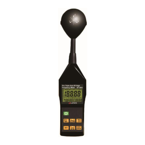
- Page 1 Pro Triple Axis RF/High Frequency Meter HF-B8G User’s Manual HB4HFB8G0000...
-
Page 3: Table Of Contents
Table of Contents Introduction ............2 Method of Operation......... 2 Fundamentals ........... 3 Electric Field Strength (E) ........ 3 Magnetic Field Strength (H) Power Density (S) The Characteristic of Electromagnetic Fields 4 Application ............5 Features............6 Identifying Parts ..........8 LCD Description .......... - Page 4 10.4 Analogue bar graph setup 10.5 Auto power off time function setup 10.6 Setting the calibration factor (CAL) Calibration Factor: ..........26 11.1 Short-term measurements: 11.2 Short-term measurements Procedure : 11.3 Long-term exposure measurements Battery Replacement ........29 External DC Power ........... 30 Safety Precautions ...........
- Page 5 HF-B8G Axis RF Meter Quick Start Guide This meter has many capabilities, including memory, alarm, date/time, average etc. which will require some study of the manual to use properly. However, you can quickly and easily begin making measurements right out of the box. Just follow these simple steps: 1.
-
Page 6: Introduction
HF-B8G 1 Introduction This meter is designed for measuring and monitoring Radio–Frequency electromagnetic field strength. The meter is calibrated precisely over the frequency range of 10MHz~8GHZ. 2 Method of Operation Press “Power” button on. To change measuring unit (mV/m), push “UNIT” button to change the unit. -
Page 7: Fundamentals
HF-B8G 3 Fundamentals Electromagnetic Pollution This meter is used to indicate electromagnetic pollution generated artificially. Wherever there is a voltage or a current, electric (E) and magnetic (H) fields arise. All types of radio broadcasting and TV transmitters produce electromagnetic fields, and they also arise in... -
Page 8: Magnetic Field Strength (H)
HF-B8G 4.1 Magnetic Field Strength (H) A field vector that is equal to the magnetic flux density divided by the permeability of the medium magnetic field strength is expressed in units of amperes per meter (A/m). In far field situations, one can calculate the magnetic field for the electric field value. -
Page 9: Application
HF-B8G three wavelengths, the far-field conditions usually hold. In near field conditions, the magnetic field value cannot be calculated from the electric field value. This meter is designed for reliable far field measurements only. 5 Application Quite often, routine maintenance and ... -
Page 10: Features
HF-B8G Wireless LAN (Wi-Fi) detection, installation. Spy camera, wireless bug finder. Cellular /Cordless: phone radiation safety level. Microwave oven leakage detection. Personal living environment EMF safety. 6 Features The meter is a broadband device for... - Page 11 HF-B8G The meter can be set to display the instantaneous value, the maximum value measured or the average value. Instantaneous and maximum value measurements are useful for orientation, e.g. when first entering an exposed area. For isotropic measurements of ...
-
Page 12: Identifying Parts
HF-B8G 7 Identifying Parts 1. RF Three-Axis sensor. 2. Liquid-crystal LCD. 3. Hold /ALARM / Up button. 4. MAX / AVG/ Right button. 5. UNIT / ENTER button. 6. XYZ / MEM / Down button. 7. Power button. 8. REC/ time / Leftward button. -
Page 13: Lcd Description
HF-B8G 8 LCD Description Primary display 15. Time unit (month: day) Hold symbol (hour: minute) Analogue bar graph (second) MAX symbol 16. MEM reading AVG symbol symbol Low battery symbol x1x10x100 unit 17. SET symbol X.Y.Z unit 18. REC symbol ALARM sound 19. -
Page 14: Specifications
HF-B8G 9 Specifications 9.1 General specifications Display type : Liquid-crystal (LCD), 4-1/2 digits maximum reading 19999. Measurement method : Digital, Tri axis measurement. Directional characteristic : Isotropic, Tri axis. Measurement range selection : ... - Page 15 HF-B8G Alarm function : adjustable threshold with ON / OFF Calibration factor CAL : adjustable Manual data memory and read storage: 200 data sets. Batteries : 9V NEDA 1604, IEC 6F22 ...
-
Page 16: Electrical Specifications
HF-B8G This tester was designed in accordance with EMC Standards in force and its compatibility has been tested in accordance with EN61326-1 (2006). 9.2 Electrical Specifications Unless otherwise stated, the following specifications hold under the following conditions: The meter is located in the far field of a source;... -
Page 17: Units Of Measurement
HF-B8G Frequency response : Sensor taking into Account the typical CAL factor : ±2.4dB(50 MHz to 1.9 GHz, 3.5 GHz to 8GHz). ±1.0dB (1.9 GHz to 3.5GHz). Isotropy deviation : Typically ± 1.0 dB (2.45GHz). Overload limit : 0.083 mW/cm ,(17.7 V/m) -
Page 18: Result Modes
HF-B8G 9.4 Result modes The bar graph display always shows the instantaneous measured dynamic range value. The digital display shows the result according to one of three modes, which can be selected. Instantaneous : The display shows the last value measured value measured by the sensor, no symbol is displayed. -
Page 19: Measurement Procedures And
HF-B8G MAX/AVG: 9.5 Measurement Procedures and Preparation Battery loading : Remove the battery cover on the back and put a 9V battery inside. Battery replacement : When the symbol of “ ” appears on the LCD display, the battery should be replaced with a new one. -
Page 20: Data Hold Key
HF-B8G 9.7 Data Hold Key: ” key to go into hold mode, and Press the “HOLD” appears on the screen to allow you to read the data. ” this key once again to deactivate it. Press >> >> > 9.8 Units Key: Change units with the “UNITS”... -
Page 21: Max / Avg Record
HF-B8G 9.9 MAX / AVG Record: ” key to switch to the next display. Press The display switches from MAX to AVG to MAX/AVG and back to MAX. ”key for 3 seconds to Press and hold disable this function. The maximum storage is up to 99 minutes and... -
Page 22: Xyz/Call
HF-B8G Over load Indication : “OL”. 9.11 XYZ/CALL: ” this key to change sensor axis Press selector :” All axis ”→“ X axis “→“ Y axis ”→ “ Z axis ”. 9.12 Alarm ON/OFF Setup ” and ” key to switch the Press hold alarm function on The “ALARM”... -
Page 23: Viewing Data Records
HF-B8G 9.13 Viewing Data Records ” key and press ” key to Press hold ” or ” view the saved data records Use key to see the next or previous records Press “ ” key to close the setup, exit the mode. -
Page 24: Clock Lcd Display
HF-B8G 9.15 Clock LCD Display ” key and press ” key for Press hold more than seconds to select the display method of the year, month, date, hour and second. This meter’s clock uses 24 hour time setting. Default time mode setting is “2010/01/07 00: 02”... -
Page 25: Clock Setup
HF-B8G (ALARM) setup 2 : Clear data logger memory setup 3 : Analogue bar graph X1.X10.X100 setup 4 : Auto power off time setup 5 : Setting the calibration factor (CAL) 10.1 Clock Setup ”... -
Page 26: Setting The Alarm Limit Value (Alarm)
HF-B8G 10.2 Setting the alarm limit value (ALARM) The alarm limit value is used to monitor the display value automatically. It controls the alarm indication function. The alarm limit value can be edited in the displayed V/m unit. The ALARM setting range is from 0.001 to 999.9V/m. -
Page 27: Del Data Logger Memory Setup
HF-B8G Press “ ” key to select the value. Press “ ” key to store the new setting value and exit. 10.3 DEL data logger memory setup ” key first and ” key to enter Press hold the Setup Mode. -
Page 28: Analogue Bar Graph Setup
HF-B8G 10.4 Analogue bar graph setup ” key first and ” key to Press hold enter the Setup Mode. ” key for three times to enter the Press analogue bar graph setting mode. The ”graph” unit is flashing displayed X1、... -
Page 29: Setting The Calibration Factor (Cal)
HF-B8G minutes. “ and ” key to change the: Press 00~99 minutes. ” key to save and exit. Press : 00 Auto power off disable. : 99 Maximum auto power off time 10.6 Setting the calibration factor (CAL) ”... -
Page 30: Calibration Factor
HF-B8G Please refer to the following calibration factors of our standard meter verified by the laboratory : (V/m) Factor (MHz) (V/m) (dB) Z Average 1800 1.00 0.77 0.68 0.85 0.77 2450 1.00 0.94 0.92 0.96 0.94 11 Calibration Factor: The calibration factor CAL serves to calibrate the result display. -
Page 31: Short-Term Measurements
HF-B8G charges. Recommendation : hold the meter steady during the measurement. 11.1 Short-term measurements: Application : Use either the “instantaneous” or the “Max .instantaneous” mode, if the characteristics and orientation of the field are unknown when entering an area exposed to electromagnetic radiation. -
Page 32: Long-Term Exposure Measurements
HF-B8G field may locally concentrate or amplify the field from a distant source. 11.3 Long-term exposure measurements Location : Place the meter between yourself and the suspected source of radiation. Make measurements at those points where parts of your body are nearest to the source of radiation. -
Page 33: Battery Replacement
HF-B8G 12 Battery Replacement warin ” appears on the If the symbol LCD, please replace the battery immediately Turn off the instrument. Remove the battery cover Replace the battery. Install the battery cover. ... -
Page 34: External Dc Power
HF-B8G 13 External DC Power External AC to DC adapter: Voltage 9VDC(8~14VDCMax) Supply current :>300mADC Socket : pin positive, ground casing external Diameter 6.3mm; internal diameter 2.0 mm 14 Safety Precautions For cleaning the instrument use a soft dry ... -
Page 35: Safety Information
HF-B8G 15 Safety Information CAUTION Before making a measurement, check if the low battery symbol” ” is shown on the display as soon as the meter is switched on. Change the battery if the symbol is displayed. In the case of prolonged storage, it is preferable to remove the battery from the meter. -
Page 36: Safety Information
HF-B8G 16 Safety Information DANGER In some cases, work in the vicinity of powerful radiation sources can be a risk of your life. Be aware that persons with electronic implants (e.g. cardiac pacemakers) are subject to particular dangers in some cases. -
Page 37: Disposal
HF-B8G 17 Disposal Caution : this symbol indicates that equipment and its accessories shall be subject to a separate collection and correct disposal EN-33... - Page 38 HF-B8G...
- Page 39 HF-B8G EMR Shielding Solutions Inc. 399 Four Valley Drive, Unit 13, Concord, Ontario, L4K 5Y7, Canada E-mail: info@emrshieldingsolutions.com www.emrshieldingsolutions.com...
Need help?
Do you have a question about the HF-B8G and is the answer not in the manual?
Questions and answers