Table of Contents
Advertisement
Quick Links
Advertisement
Table of Contents

Related Manuals for Panasonic AU-VCVF10G


Summary of Contents for Panasonic AU-VCVF10G
-
Page 1: Operating Instructions
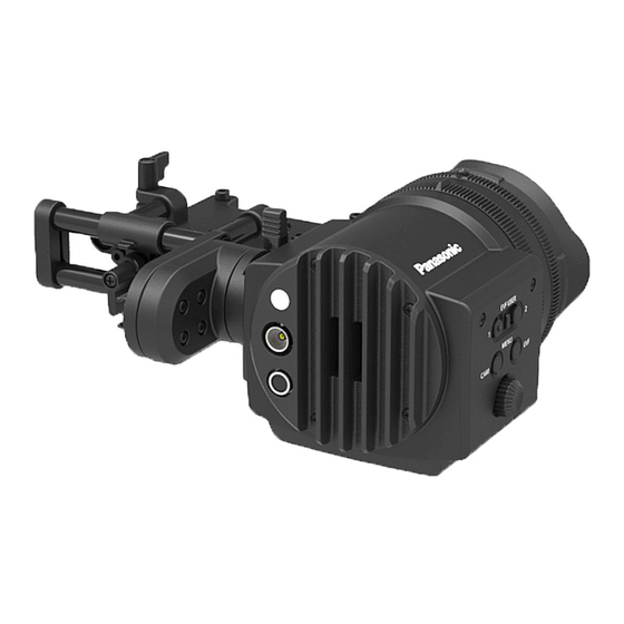
Operating Instructions Electronic HD Color View Finder AU-VCVF10G Model No. Before operating this product, please read the instructions carefully and save this manual for future use. Before using this product, be sure to read “Read this first!” (pages 2 to 3). -
Page 2: Read This First
Read this first! Read this first! indicates safety information. WARNING: CAUTION: f To reduce the risk of fire, do not expose Do not remove panel covers by unscrewing. this equipment to rain or moisture. No user serviceable parts inside. Refer servicing to qualified service personnel. f To reduce the risk of fire, keep this equipment away from all liquids. -
Page 3: Fcc Warning
Read this first! indicates safety information. FCC NOTICE (USA) This device complies with part 15 of the FCC Rules. Operation is subject to the following two conditions: (1) This device may not cause harmful interference, and (2) this device must accept any interference received, including interference that may cause undesired operation. - Page 4 AEEE Yönetmeliğine Uygundur. AEEE Complies with Directive of Turkey. The rating plate is on the underside of the unit. Manufactured by: Panasonic Corporation, Osaka, Japan Importer’s name and address of pursuant to EU rules: Panasonic Marketing Europe GmbH Panasonic Testing Centre...
- Page 5 f All names, company names, product names, etc., contained in this document are trademarks or registered trademarks of their respective owners. How to read this document r Illustrations f Illustrations may differ from the actual product. r Conventions used in this manual f Words and phrases in [ ] brackets indicate details and content displayed in the viewfinder or control panel.
-
Page 6: Table Of Contents
Contents Contents Read this first! Before using the camera Accessories Description of Parts Left side Front Rear Adjusting and setting the viewfinder Adjustment method Viewfinder status display Lamp display Status display Storing Cautions when storing the camera recorder Specifications... -
Page 7: Before Using The Camera
Before using the camera Before using the camera f Since the viewfinder uses organic EL, if the same image or letters are allowed to be displayed for a long time, the image may be burned into the screen. There is no problem with the recorded images. Switch the screen by turning off the screen or by using the eye sensor, etc. -
Page 8: Accessories
Accessories Accessories f Slider unit f Slider unit mounting screw (2 pcs.) f BNC cable f DC cable f Eye cup (already attached to the electronic HD color view finder) f Eye piece filter (already attached to the electronic HD color view finder) NOTE t After unpacking the product, dispose of the packing material properly. -
Page 9: Description Of Parts
Description of Parts Description of Parts Left side 1 <EVF USER 1>/<EVF USER 2> buttons User-selected functions can be assigned to each button. Pressing a button performs the assigned function. Functions are set on the viewfinder menu. 2 <CAM MENU> button Displays the camera menu screen. -
Page 10: Rear
Description of Parts 2 Video signal input terminal An input terminal for 3G/HD-SDI video signal input. Use the supplied BNC cable or the 5C-FB equivalent double-shielded cable for the cable to connect to this terminal. 3 <DC IN 12V> terminal An input terminal for power supply input. -
Page 11: Top
Description of Parts 3 Eye piece filter Protective filter against dust, water, and moisture. Use the camera with this attached. 4 Stopper Used when removing the viewfinder from the slider unit. 1 Lock lever (left/right position) Adjusts the position of the viewfinder (left/right). 2 Lock lever (front/back position) Adjusts the position of the viewfinder (front/back). -
Page 12: Adjusting And Setting The Viewfinder
Adjusting and setting the viewfinder Adjusting and setting the viewfinder The camera’s panel is OLED (organic EL). Positioning your eye near the viewfinder will trigger the eye sensor to automatically display the image. Adjustment method a: Lock lever (left/right position) b: Lock lever (front/back position) c: Visibility adjustment ring d: Zoom ring... - Page 13 Adjusting and setting the viewfinder r Zoom adjustment Adjust by turning the zoom ring. Adjust to a comfortable view angle while checking the video. Perform adjustment when adjusting the focus. Vignetting may occur around the screen of the enlarged image.
-
Page 14: Viewfinder Status Display
Viewfinder status display Viewfinder status display In addition to video, the viewfinder displays messages, a center marker, safety zone marker, zebra patterns, and other information that indicate the camera settings and operation status. Lamp display 1 Green tally lamp Lights up in green when green tally signals are received. 2 Red tally/recording lamp Lights up in red during recording or when red tally signals are received. - Page 15 Viewfinder status display [EVF MENU] operation Press and hold the <EVF MENU> button for at least two seconds. [EVF MENU] is displayed. [EVF MENU] list r [DISPLAY SETUP] Item Description of settings [COLOR] Adjusts the color level. [−32] - [31] f Factory setting: [0] [CONTRAST] Adjusts the contrast.
- Page 16 Displays the firmware version of the viewfinder. NOTE t For the function that can be selected when connected to the memory card camera-recorder AU-V35LT1G, visit the Panasonic website (http://pro-av.panasonic.net/en/manual/index.html) and refer to the Operating Guide for VariCam LT (HTML version).
-
Page 17: Storing
Storing Storing Cautions when storing the camera recorder Store each in a location with low humidity and that the temperature is relatively constant. r Camera body f Wrap the camera recorder with a soft cloth so that dust does not get into it. -
Page 18: Specifications
Specifications Specifications Power DC e 12 V (supplied from the camera body) 3.7 W indicates safety information. Ambient operating temperature 0 °C - 40 °C (32 °F - 104 °F) Ambient operating humidity 10% - 85% (no condensation) Storage temperature −20 °C - 60 °C (−4 °F - 140 °F) Weight Approx. - Page 19 Web Site: http://www.panasonic.com © Panasonic Corporation 2016...
Need help?
Do you have a question about the AU-VCVF10G and is the answer not in the manual?
Questions and answers