Table of Contents
Advertisement
Advertisement
Table of Contents

Related Manuals for Sailor RT5022


Summary of Contents for Sailor RT5022
- Page 1 SAILOR RT5022 VHF DSC Operation Manual PRELIMINARY...
-
Page 2: Introduction
- a position which has been maintained by means of constant and extensive product development. We have a worldwide network of dealers with general agencies in ® more than 80 countries. All our dealers are specially trained to service all your SAILOR products. About this manual This manual is for the daily user of the system. -
Page 3: Quick Dsc Distress Call
QUICK DSC DISTRESS CALL (only for emergency use) 1. If necessary, switch on by pressing the ON/OFF button. 2. Lift up lid covering the orange DISTRESS key and press for 5 seconds. 3. Alarm indicator light will flash and will be accompanied by a sound. Distress is sent after continuous tone. -
Page 4: Your Vhf At A Glance
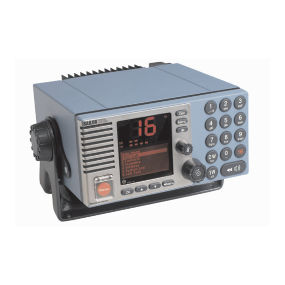
Your VHF at a glance Alarm Call 0191 - 05 1. Loudspeaker 7. Dimming button 2. Volume level indicator 8. Menu button 3. Squelsh level indicator 9. Mute alerts 4. Indicator lamps. Condition when lit: 10. Keyboard. 1W: 1 watt transmission mode. 11. -
Page 5: Table Of Contents
Contents Introduction ..........................ii About this manual ........................ ii Abbreviations used in this manual ..................ii QUICK DSC DISTRESS CALL ....................iii MAYDAY PROCEDURE ......................iii Your VHF at a glance ....................... iv Radio Communication in brief ..................3 Powering VHF ......................3 Operating VHF radio communication ................. - Page 6 DSC Operations in Detail ....................14 MMSI Number ......................14 Group MMSI Number ....................14 Differentiating Incoming Calls by Ringing Tones ............. 14 Working Channel ...................... 15 Contact List ....................... 15 Settings for DSC ....................... 17 Implicit Behaviour for Operations with DSC ............. 18 Radio Configuration and Settings ................
-
Page 7: Radio Communication In Brief
1 Radio Communication in brief Powering VHF The VHF is turned on by a single push on the ON/OFF/Vol button. The VHF is turned off by pressing the ON/OFF/Vol button for 3 seconds. Always indicated with a count down window in the information display, except if the radio is powered down in distress state. -
Page 8: Making A Radiotelephone Call
Making a Radiotelephone Call A radiotelephone call is preferably to be commenced using DSC. Alternatively the following public calling procedure shall be used: 1. Select channel 16 (by pressing ) or other agreed channel. 2. Lift the handset. 3. Press the PTT key and make your call. First, say the name of the station you are calling three times. -
Page 9: Channel Selection
Channel Selection The system is defaulting to channel 16 after a normal power-on. Channels can be selected using the (increasing to next valid VHF channel) or (decreasing channel). Channels can also be entered using the numeric keypad. The active working channel is always shown in the upper display. Dual Watch Dual watch is a mode where the priority channel (16) is scanned periodically for a signal while listening on a working channel. -
Page 10: Dimming
1.11 Dimming To adjust the light intensity the Dim button is pressed. While the Dim button is pressed the intensity is changing. Releasing Dim will maintain the current light intensity. A renewed pressing of the Dim button will change the direction of light intensity change. If the VHF is dimmed to zero, any key press will wake up the light to a minimum visible at night. -
Page 11: Basic Dsc Operations
2 Basic DSC Operations When switched on, your VHF automatically monitors channel 70 for incoming DSC calls. Menu Operation To operate DSC functionality the menu system is used. The main menu can be activated by pressing . From the main menu all parts of the menu tree can be reached (see chapter: Menu Tree). -
Page 12: Transmitting Dsc Calls
If you are busy you can chose to handle the call a little later (e.g. by pushing which will stop the alarm sound. Once you are ready to accept the call, lift the handset or press . Your choices handling the particular call will now appear. Follow the instructions. If an individual call is received it will not be acknowledged before you accept the call. -
Page 13: Call A Group Of Ships
Call a Group of Ships To call a group of ship stations, enter the Group Call menu (1.3) and follow the instructions. Have the group MMSI number (0*) ready if it is not available via the contact list. Create Emergency Calls In the category of emergency calls (1.4) you will find the Emergency following menu:... - Page 14 0505...
-
Page 15: Your Vhf In Detail
3 Your VHF in detail Abnormal Power-down If for any reason the main power disappears for a period less than 10 minutes, the VHF will be able to turn itself on when power is resumed (without pushing ON/OFF). If the VHF was abnormally powered down, for less than 1 minute the VHF will start up with the same settings as before the power failure took place (communication channel, volume, squelch settings, etc.). -
Page 16: Duplex Channels
Duplex Channels If duplex channels are selected in the channel table (see chapter: Maritime Channels) the VHF will operate in semi-duplex mode meaning the VHF is operated simplex but using two different frequencies for receive and transmit. ATIS (Inland Waterways Only) ATIS is mandatory to use in inland waterways on e.g. -
Page 17: Creating Scan Tables
The active scanning window is active in the graphics display for 30 seconds (or pressing OK). Then it turns off. After this window has been turned off, scanning can be turned off using the following: • Lifting handset off hook •... -
Page 18: Dsc Operations In Detail
4 DSC Operations in Detail MMSI Number To operate VHF with DSC the equipment need to be configured with your vessels MMSI number. If not configured before installation the VHF will inform you at start-up to program the MMSI number. The vessels MMSI number is programmable from the DSC menu (4.5). -
Page 19: Working Channel
If an individual call acknowledgement is received, an alarm tone is activated that is equal to the alarm tone used for receiving a call request of the same type. Calls that are not received as distress calls or calls with category distress or urgency will always engage the prescribed alarm sound. - Page 20 The alphanumeric keypad can be used for quick search for items (using wheel mode). Selecting a contact will show Call Contact data for that contact. Example: Name: Peters Oil MMSI no: 003456789 PSTN no: 0045 68098765 When OK is pressed the appropriate call generator will be initialized, based on the data.
-
Page 21: Settings For Dsc
After having pressed OK the contact information looks as the following: Add Contact Name: Anders Fisker MMSI no: PSTN no: When the necessary data has been entered is pressed. If neither a valid MMSI number, OK/change <Menu/back nor a PSTN number is entered, no contact is added to the Contact list. -
Page 22: Implicit Behaviour For Operations With Dsc
4.6.2 Automatic Acknowledgement The VHF can be set up to automatic acknowledge the following calls: • Safety Position Requests - Default disabled after power-up • Safety Test Requests - Default enabled after power-up • Routine Polling Requests - Default enabled after power-up After power-up the behavior can be changed from menu 4.5.4. - Page 23 4.7.2 Transmitting Undesignated Distress Undesignated distress (solely created using the DISTRESS button) does not show any message prior to the actual transmission. The following message will be sent: Format Specifier: Distress (112) Self-Id: <Your MMSI number> Nature of Distress: Undesignated (107) Distress Coordinates: Automatically inserted if position is available (e.g.
-
Page 24: Radio Configuration And Settings
4.7.5 Priority of DSC versus VHF If a situation occur where a conflict between the VHF and the DSC functionality occurs (for instance voice transmission on a working channel – using PTT, simultaneously with trans- mission of a DSC call), the DSC transmission will be prioritized. As a consequence the following VHF functions may need to be re-initiated if DSC activity has occurred while these were active: •... -
Page 25: Errors And Warnings
5 Errors and Warnings Errors and warnings are shown on the screen accompanied with the sounds shown in the figure below: 60 sec. TONE SIGNAL 1 sec. 8 sec. ERRORS WARNING & INFO 39718 If you get an error or warning message you will always be able to shut off the alarm. Press to finish on-going radiotelephony. -
Page 26: Troubleshooting
Troubleshooting If you doubt that your VHF system works properly, it is of great importance that you find the reason and assure that the equipment is properly serviced if any of the devices are failing. You should contact your authorized dealer for tecnical support of your equipment. But, before you do that you have a list of actions you can go through to fix the problem by yourself and save time. - Page 27 5.2.2.2 Display Test The information/message display is an LCD screen. A test of all pixels in the screen is executed in menu 6.2. Triangles are displayed on the screen. 5.2.2.3 LED Test You can verify that all light indicators including the channel display can be lit. Running the LED test (6.3) will turn on all indicators for 2 seconds, whereafter these will return to their previous state.
- Page 28 If an alarm panel (APYYYY) is connected please check there is a light in the red “VHF DISTRESS” button. If not lit, fuses might need replacement in the alarm panel before the serial bus is operational. Communication problems will not affect VHF unit functionality. 5.2.5 Device Failure If any of the checks descibed above does not explain or help to solve the problems you have...
-
Page 29: Menu Tree
5.2.8 Channel Not Free 5.2.8.1 DSC Channel not free Symptom: DSC transmission is delayed DSC calls that are not distress or urgency calls will not be sent if the VHF is in the middle of decoding a DSC call. The transmission will be delayed until decoding has finished. 5.2.8.2 Working Channel not free Symptom: No proposed working channel in station call In a DSC station call a working channel is proposed. - Page 30 Settings Position & Tim e 4.1.1 Set Position & Time 4.1.2 Radio Time 4.1.3 Pos ition Info 4.2 Display Contrast Audio 4.3.1 Handset Volum e 4.3.2.1 Warning 4.3.2 Alarm Tones 4.3.2.2 Routine 4.3.2.3 Safety Call Channels 4.4.1 Channel Mode 4.4.1.1 Int 4.4.1.2 US 4.4.1.3 BIN 4.4.1.4 CAN...
-
Page 31: Optional Functional Devices
7 Optional Functional Devices The maximum system configuration possible with your VHF installation with VHF is shown in the first part of the installation section. The present chapter will describe the functionality and behaviour of the following optional functional devices: •... - Page 32 7.1.2 Operation The optional handset is intended for VHF radiotelephony only. There will be no DSC functionality supported except for: • The functionality or lifting the CU handset follows the default handset on the main radio (see Section DSC receive), when receiving a DSC call. •...
- Page 33 7.1.6 Squelch Squelch level can be adjusted using the buttons. Operating the buttons will contribute to the global squelch setting on the radio. Squelch indicators on the handset CU and on the main unit will always follow each other regardless of the control input used for adjustment.
-
Page 34: Alarm Panel
7.1.11 Multiple Handsets in the System If multiple handsets are connected in the system the following priority is given (to PTT – microphone control) if multiple handsets are lifted: • Default handset is always given priority if lifted. • Any optional handset lifted first takes priority over another optional handset. A warning “OC”... -
Page 35: Printer
Printer If a printer is connected in the system you have the possibilities to print out single DSC messages, DSC logs – in both cases accessible from the DSC log menu. You can also print out errors and warnings from the event log. The VHF will send messages via the printer driver implemented in the LAN interface. -
Page 36: Maritime Channels
8 Maritime Channels International Channels Channels SIMPLEX DUPLEX Channels SIMPLEX DUPLEX Intership Port Port Public Intership Port Port Public 156,050 160,650 156,025 160,625 156,100 160,700 156,075 160,675 156,150 160,750 156,125 160,725 156,200 160,800 156,175 160,775 156,250 160,850 156,225 160,825 156,300 156,300 156,275 160,875 156,350 160,950 156,325 160,925... -
Page 37: Us Channels
US Channels Channels SIMPLEX DUPLEX Channels SIMPLEX DUPLEX Channels 156,050 156,050 162,550 156,075 156,075 162,400 156,150 156,150 162,475 156,175 156,175 162,425 156,250 156,250 156,225 156,225 162,450 156,300 156,300 156,275 156,275 162,500 156,350 156,350 156,325 156,325 162,525 156,400 156,400 156,375 156,375 161,650 156,450 156,450 156,425 156,425... -
Page 38: Bi Channels
BI Channels Channels SIMPLEX DUPLEX Channels SIMPLEX DUPLEX Intership Port Port Public Intership Port Port Public 156,050 160,650 156,025 160,625 156,100 160,700 156,075 160,675 156,150 160,750 156,125 160,725 156,200 160,800 156,175 160,775 156,250 160,850 156,225 160,825 156,300 156,300 156,275 160,875 156,350 160,950 156,325 160,925 156,400 156,400... -
Page 39: Installation
9 Installation Mounting possibilities 39653 VHF with Mounting Bracket tegning mangler Mounting option tegning mangler Drilling plan tegning mangler Weight: 3.6 kg Mounting Bracket 1.0 kg 0505... - Page 40 Handset for Transceiver Drilling plan * 120 39655 Space for handset access Weight Handset for Transceiver 0.4 kg 0505...
- Page 41 Semifunctional Control Unit Drilling plan Space for handset access 39654 Weight : Semifunctional Control Unit 1.2 kg Remote control units are connected as shown on xxx. Adding a single CU After the CU is connected the unit can be operated straight forward without any additional configuration.
- Page 42 Connection Box Drilling plan 4 pcs. ø6 258.4 9.75 Mounting * 50 * 50 * Free space for mounting, ** Free space for cable entry. 39656 Weight Connection Box 1.7 kg 0505...
- Page 43 Extension Box Drilling plan 4 pcs. ø6 141.4 Mounting * 50 * 50 Weight Extension Box ??0.7 kg * Free space for mounting, ** Free space for cable entry. 39657 0505...
- Page 44 LAN Box Drilling plan 74.5 Mounting * 50 Weight LAN Box 0.3 kg * 50 * Free space for mounting, ** Free space for cable entry. 39658 0505...
-
Page 45: Interface Connections
Interface connections VHF (rear view) Option FUSE 12-24V DC Sparc II Bus Handset Main Antenna DSC Antenna 39815 0505... - Page 46 Connection box board 639121 J3 & J4 MOUNTED = RT502X LS CU 1 CU 2 J3 & J4 NOT MOUNTED = CU1 LS J3 & J4 MOUNTED = RT502X LS J3 & J4 NOT MOUNTED = CU2 LS RT502X OPTIONS RT502X VDR+ +12.5V...
- Page 47 Interfaces Options Connections Signal Cable Connection Connection Signal description Ships cable Options Connector Designation 8 twisted pairs In from VHF External conn. overall screen 15-pin D-sub male Mixed Rx/Tx audio output for recording. VDR+ pin 1 X1-1 X2-1 pair no. 1 Galvanically isolated, balanced signal, pair no.
- Page 48 9.2.1 System Block diagram with Connection Box and 2 x Extension Box 0505...
- Page 49 Cable Connection Diagram OPTIONS CONNECTIONS SPARC II BUS CONNECTIONS RT502X OPTIONS RT502X HANDSET I HANDSET 2 ALARM VDR+ +12.5V VDR- DATA+ AUX2 DATA- AUX2 TX AF+ AUX1 TX AF- AUX1 EXT LS1 +12.5V EXT LS1 RX AF+ CALL RX AF- CALL +12.5V EXT LS2...
- Page 50 9.2.2 System Block diagram with Extension Box 0505...
-
Page 51: Power Supply
Cable Connection Diagram X6 : J1 & J2 MOUNTED = VHF J1 & J2 NOT MOUNTED = CU EXT LS CU LS EXT LS VHF/CU EXT LS CU LS EXT LS VHF/CU +12.5V DATA+ DATA- TX AF+ TX AF- +12.5V RX AF+ RX AF- +12.5V... - Page 52 9.4.2 RX/TX antenna In installations consisting of two or more VHF radios it is important to ensure the optimum performance of these by carefully selecting the mutual antenna positions. In general the highest possible RF attenuation between the VHF RX/TX antennas in the installation should be sought for.
- Page 53 Example of VHF antenna arrangement. 0505...
-
Page 54: Technical Specification
10 Technical specification General Normal channels All int. channels. Up to 30 private channels in 3 separate banks designated F,P or L. Each bank contains 10 private channels. US channels All US channels according to Radio Regulations. BI channels All BI channels according to Radio Regulations. Channel spacing 25 KHz Operation modes... - Page 55 DSC facilities DSC operation According to Rec. ITU-R M.541-9 and Rec. ITU-R M.689-2 DSC protocol According to Rec. ITU-R M.493-11 Class A Navigator interface According to IEC 61162-1 GLL, RMC, ZDA, GGA, VTG, GNS Symbol error rate below 1*10 -121 dBm or 0.20 µV p.d. Modulation 1700 Hz ±...
- Page 56 0505...
Need help?
Do you have a question about the RT5022 and is the answer not in the manual?
Questions and answers