
Related Manuals for Geist Watchdog 100

Summary of Contents for Geist Watchdog 100
- Page 1 Instruction Manual Environment Monitor with Output Relay and Optional PoE Watchdog 100 Firmware v3 Geist 1821 Yolande Ave., Lincoln, NE 68521 800.432.3219 | 402.474.3400 | geistglobal.com...
-
Page 2: Table Of Contents
Resetting the Unit ................................31 Service and Maintenance ..............................31 More Technical Support ..............................31 Using Microsoft Exchange as an SMTP server ........................ 31 Table of Figures .................................. 33 Revision History .................................. 34 GM1118 - Watchdog 100 Series User Manual BB3.0 Revision Date: 12/31/2015... -
Page 3: Specifications
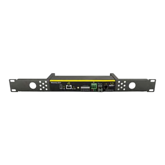
The Watchdog 100 can be optionally configured at the factory to support Power-Over-Ethernet (PoE). The Watchdog 100 has a built-in sensor to monitor temperature, humidity and dew point, as well as one port for adding remote sensors. The Watchdog 100 also has four I/O ports for connecting additional external 5Vdc sensors such as Flood and Door Sensors. -
Page 4: Remote Sensors
(G)RTHD sensors built prior to 2010. If you desire to add (G)RTAFHD3 sensors to an existing installation currently utilizing incompatible sensors, please contact Customer Service for installation options. GM1118 - Watchdog 100 Series User Manual BB3.0 Revision Date: 12/31/2015... -
Page 5: Environmental
Watchdog 100. Caution: The Watchdog 100 unit has not been evaluated for and should not be used in any application in which the failure of the hardware could lead to death, personal injury or severe physical or property damage or environmental damage (collectively, “High-Risk Applications”), including but not limited to the operation of... -
Page 6: Networking
Geist expressly disclaims any express or implied warranty or condition of fitness for High-Risk Applications. Networking Protocols HTTP, HTTPS (TLS v1.2), SMTP/POP3, ICMP, DHCP, TCP/IP, NTP, Syslog, SNMP (v1/2c/3) Ethernet Link Speed 10/100 Mbps;... -
Page 7: Installation
Guidelines If the Watchdog 100 is installed in a cabinet the ambient temperature of the rack should be no greater than 45 C. Install the Watchdog 100 such that the amount of airflow required for safe operation of equipment is not compromised. -
Page 8: Network Overview
Default IP Address The Watchdog 100 has a default IP address for initial setup and access to the unit if the assigned address is lost or forgotten. Once an IP address is assigned to a unit, the default IP address is no longer active. To restore the default IP address, press the reset button located beside the network connector and hold for approximately 20 seconds. -
Page 9: Figure 5: Os X Network Settings For Initial Setup. Image Varies Depending On Os X Versions
Figure 5: OS X network settings for initial setup. Image varies depending on OS X versions. Apply changes. The unit should now be accessible in a web browser via the unit’s permanent IP address: http://192.168.123.123/. GM1118 - Watchdog 100 Series User Manual BB3.0 Revision Date: 12/31/2015... -
Page 10: Web Interface
Prohibited characters for username only are: $&`:<>[ ] { }"+%@/ ; =?\^|~', 4. Alarms and Warnings Indicates the number of Alarms and Warnings currently occurring, if any. Mouse over to read description. GM1118 - Watchdog 100 Series User Manual BB3.0 Revision Date: 12/31/2015... -
Page 11: Overview Page Configuration
8. Relay Displays and configure relay state (Energize/De-energize). The Watchdog 100 has one relay that can be operated remotely or set automatically opened or closed based on alarm conditions. Friendly names for the relay give the option of changing the state name from “Energized/De-energized” to something more meaningful to user. -
Page 12: Figure 8: Device Data Delete Dialog
AC: 30Vrms, 1 A Relay Configuration The Watchdog 100 units provide one output relay that can be operated remotely or set to automatically open or closed based on alarm conditions. A relay in non-latching mode will automatically energize and de-energize as its associated alarms trip and clear. -
Page 13: Alarms And Warning Page
1. State: Shows the status of each Event. Empty: No alert condition. - This symbol indicates that this particular "Warning" event has been tripped. A tripped warning event displays in orange. GM1118 - Watchdog 100 Series User Manual BB3.0 Revision Date: 12/31/2015... -
Page 14: Figure 12: Add Alarm Dialog
Figure 12: Add Alarm Dialog 2. Set the desired conditions for this Event as follows: a. Select the Name of the device you wish to set an event on. GM1118 - Watchdog 100 Series User Manual BB3.0 Revision Date: 12/31/2015... -
Page 15: Figure 13: Add Valid Time Dialog
To determine where the alert notifications will be sent to when this particular Alarm or Warning event occurs, click the Add icon to create a new action, then select the desired options from the drop-down menu: Figure 14: Add Target Dialog GM1118 - Watchdog 100 Series User Manual BB3.0 Revision Date: 12/31/2015... -
Page 16: Figure 15: Multiple Target Delays And Repeats
Figure 16: Modify Target Dialog To remove a notification Action entirely, click the Delete icon to remove the action from the list, then click Delete to confirm. GM1118 - Watchdog 100 Series User Manual BB3.0 Revision Date: 12/31/2015... -
Page 17: Cameras Page
Clicking on the camera image opens the camera’s website in a new browser window. Note: Some cameras require additional software downloads to display live video in a web browser. Figure 18: Cameras Page GM1118 - Watchdog 100 Series User Manual BB3.0 Revision Date: 12/31/2015... -
Page 18: Figure 19: Add Camera Dialog
2. Make the changes. Click Save when finished. Figure 20: Modify Camera Dialog Deleting a Camera 1. Click the Delete icon. Confirm the prompt. Figure 21: Delete Camera Dialog GM1118 - Watchdog 100 Series User Manual BB3.0 Revision Date: 12/31/2015... -
Page 19: Logging Page
Logging Page Configuration Adding Graph 1. Check the box next to the desired measurement. 2. Choose the Time Range (15 minutes to 30 days). 3. Click Display/Refresh button to display changes. GM1118 - Watchdog 100 Series User Manual BB3.0 Revision Date: 12/31/2015... -
Page 20: Figure 23: Add Data Graph
3. Follow save link prompt. Figure 24: Download Data Clear Data Log 1. Click Clear the Log button. Note: all previously recorded data will be deleted. 2. Confirm deletion. Figure 25: Clear Data GM1118 - Watchdog 100 Series User Manual BB3.0 Revision Date: 12/31/2015... -
Page 21: System User Accounts Page
Note that account’s username cannot be changed after the account is created. b. Administrator: If set to True, this account has Administrator-Level access to the unit, and can change any setting. GM1118 - Watchdog 100 Series User Manual BB3.0 Revision Date: 12/31/2015... -
Page 22: Figure 28: Language And Password Update Page
Log Out hyperlink at the top right-hand corner of the web page, as shown here: Figure 28: Language and Password Update Page GM1118 - Watchdog 100 Series User Manual BB3.0 Revision Date: 12/31/2015... -
Page 23: Network Page
Just stop or close the browser window, then type in the new IP address into the browser's address bar, and the unit will be accessible. GM1118 - Watchdog 100 Series User Manual BB3.0 Revision Date: 12/31/2015... -
Page 24: Email Page
Target Email addresses can be configured as follows: Figure 31: Configuration Target Email Info Legend of icons/buttons: 1. Add new target email address. 2. Modify existing target email address. 3. Delete existing target email address. GM1118 - Watchdog 100 Series User Manual BB3.0 Revision Date: 12/31/2015... -
Page 25: Snmp Page
Simple Network Management Protocol (SNMP) can be used to monitor the unit's measurements and status if desired. SNMP v1, v2c and v3 are supported. In addition, alarm traps can be sent up to two IP addresses. Figure 32: SNMP Page GM1118 - Watchdog 100 Series User Manual BB3.0 Revision Date: 12/31/2015... -
Page 26: Figure 33: Snmp Configuration Section
2. Enter the IP Address which the trap should be sent to, select the trap Version to be used (v1, v2c, or v3), and click Save. Once completed, a test trap may be sent by clicking on the envelop icon (Send Test Trap). GM1118 - Watchdog 100 Series User Manual BB3.0 Revision Date: 12/31/2015... -
Page 27: Syslog Page
Syslog data can be captured remotely but must first be setup and enabled via the Syslog Page. Note that this function is primarily useful for diagnostic purposes, and should normally be left Disabled unless advised to enable it by Geist technical support for troubleshooting a specific issue. -
Page 28: Time Page
The Guest account will only be able to view the device with the options set here. Figure 39: Locale Page GM1118 - Watchdog 100 Series User Manual BB3.0 Revision Date: 12/31/2015... -
Page 29: Restore Defaults Page
Use the Firmware Update Page to load firmware updates into the unit. Firmware updates, when available, can be found on the Geist website: http://www.geistglobal.com/support/firmware. You can also subscribe to a mailing list, to be notified of when firmware updates become available. -
Page 30: Help Info Page
The unit's current firmware versions, network information, and manufacturer support information is also here. Figure 42: Help Info Page Help Support Site Technical support and documentation can be found at http://www.geistglobal.com/support/manuals GM1118 - Watchdog 100 Series User Manual BB3.0 Revision Date: 12/31/2015... -
Page 31: Technical Support
Using Microsoft Exchange as an SMTP server If your facility uses a Microsoft Exchange Email server, it can be used by the WATCHDOG 100 to send Alarm and Warning notification Emails if desired. However, the Exchange server may need to be configured to allow SMTP connections from the unit first, as later version of Exchange often have SMTP services or basic authentication disabled by default. - Page 32 Finally, once you have enabled SMTP, relaying, and the AUTH LOGIN Basic Authentication method, you may also need to create a user account specifically for the WATCHDOG 100 to log into. If you have already created an account prior to enabling the SMTP Send Connector, or you are trying to use an already-existing account created for another user, and the WATCHDOG 100 still cannot seem to connect to the Exchange server, the account probably did not properly inherit the new permissions when you enabled them as above.
-
Page 33: Table Of Figures
Figure 1: Flood Sensor Wiring Example ..........................4 Figure 2: Door Sensor Wiring Example ..........................4 Figure 3: Watchdog 100 Mounting Options ..........................7 Figure 4: Network settings for initial setup. Images varies depending on Windows versions..........8 Figure 5: OS X network settings for initial setup. Image varies depending on OS X versions..........9 Figure 6: Overview Page –... -
Page 34: Revision History
Revision History Revision Date Notes Approved By 8/9/2012 Initial Version 2/13/2015 Change Product Name and Update Interface. 12/30/15 BB3.0 Upgrade Changes and A2D support GM1118 - Watchdog 100 Series User Manual BB3.0 Revision Date: 12/31/2015...
Need help?
Do you have a question about the Watchdog 100 and is the answer not in the manual?
Questions and answers