Sign In
Upload
Download
Table of Contents
Contents
Add to my manuals
Delete from my manuals
Share
URL of this page:
HTML Link:
Bookmark this page
Add
Manual will be automatically added to "My Manuals"
Print this page
×
Bookmark added
×
Added to my manuals
Manuals
Brands
Dixie Chopper Manuals
Lawn Mower
Zee 2 2348
Operation & maintenance manual
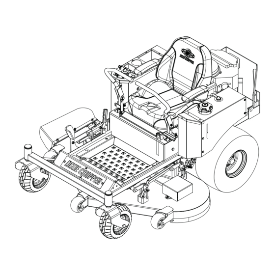
Dixie Chopper Zee 2 2348 Operation & Maintenance Manual
2017
Hide thumbs
1
Table Of Contents
2
3
4
5
6
7
8
9
10
11
12
13
14
15
16
17
18
19
20
21
22
23
24
25
26
27
28
29
30
31
32
33
34
35
36
37
38
39
40
41
42
43
44
45
46
47
48
49
50
51
52
53
54
55
56
page
of
56
Go
/
56
Contents
Table of Contents
Bookmarks
Table of Contents
Table of Contents
Contents
Introduction 2
Important
Product Identification
Serial Numbers
Guidelines for the Disposal of Scrap Products
Safety
How to Operate Safely
Maintenance and Storage
Important Safety Notes
Specifications 4
Engine Specifications
Dimensions and Weights
Mower Specification
Cutting Unit Specification
Belt Specification
Recommended Lubricants
Accessories
Support Literature
Decals 5
Safety Decals
Instruction Decals
Controls
Mower Controls
Control Panel
Steering Control Levers
Parking Brake
Cutting Unit HOC Pedal
Lift Stop Lever
Operation 7
Daily Inspection
Interlock System
Operating Procedure
Starting the Engine
To Stop the Engine
Driving
Height of Cut
Mowing
Mowing on Slopes
Towing the Mower
Maintenance and Lubrication Charts
Maintenance Chart
Fluid Requirements
Maintenance
General Precautions
Engine
Engine Oil
Engine Air Filter
Engine Exhaust
Fuel
Charge the Battery
Battery
Drive Axle Fluid
Tires
Wheel Mounting Procedure
Folding ROPS Accessory
Air Cooling System
Inspecting Blades
Sharpening Blades
Electrical System
Belts
Care and Cleaning
Mower Storage
Adjustments 10
General Precautions
Steering Lever Adjustment
Forward Speed Limit Screws
Torque Specification
Problem Solving
General
Advertisement
Quick Links
1
Maintenance Chart
2
Fluid Requirements
3
Engine Oil
4
Drive Axle Fluid
5
Electrical System
Download this manual
2017 ZEE 2 Safety, Operation & Maintenance Manual
700561
2/2017
Table of
Contents
Previous
Page
Next
Page
1
2
3
4
5
Advertisement
Table of Contents
Need help?
Do you have a question about the Zee 2 2348 and is the answer not in the manual?
Ask a question
Questions and answers
Related Manuals for Dixie Chopper Zee 2 2348
Lawn Mower Dixie Chopper 2007 Reference Manual
(124 pages)
Lawn Mower Dixie Chopper 2014 Zee 2 Owner's/Operator's Manual
Chopper (24 pages)
Lawn Mower Dixie Chopper Zee 2 2354 Operation & Maintenance Manual
2017 (56 pages)
Lawn Mower Dixie Chopper Magnum Eagle Owner's Manual
(36 pages)
Lawn Mower Dixie Chopper 8084019 Parts Manual
Lawn mower (32 pages)
Lawn Mower Dixie Chopper 8077629 Parts Manual
Lawn mower (48 pages)
Lawn Mower Dixie Chopper 2013 Silver Eagle Owner's/Operator's Manual
(24 pages)
Lawn Mower Dixie Chopper Silver Eagle Operation Manual
Lawn mower (28 pages)
Lawn Mower Dixie Chopper XCaliber Owner's Manual
(20 pages)
Lawn Mower Dixie Chopper Pursuit 1832S Safety, Operation And Maintenance Manual
(52 pages)
Lawn Mower Dixie Chopper LX2002-42 Manual
Lx series; x series; xf series; xw series (78 pages)
Lawn Mower Dixie Chopper Iron Eagle 2350 Owner's Manual
(28 pages)
Lawn Mower Dixie Chopper Classic 2760 Owner's/Operator's Manual
(24 pages)
Lawn Mower Dixie Chopper XCALIBER 2011 Manual
(44 pages)
Lawn Mower Dixie Chopper Vortex 2008 Installation & Owner's Manual
(24 pages)
Lawn Mower Dixie Chopper Xcaliber Owner's Manual
(28 pages)
This manual is also suitable for:
Zee 2 2348br
Zee 2 2354 br
Zee 2 2342ko
Zee 2 2348ko
Zee 2 2354ko
Zee 2 2354
...
Show all
Blackhawk 2248kw
Blackhawk 2454kw
Blackhawk hp 2248kw
Blackhawk 2460kw
Blackhawk hp 2454kw
Blackhawk hp 2548koe
Blackhawk hp 2460kw
Blackhawk hp 2554koe
Blackhawk hp 2560koe
Blackhawk 2554br
Blackhawk 2560br
Table of Contents
Save PDF
Print
Rename the bookmark
Delete bookmark?
Delete from my manuals?
Login
Sign In
OR
Sign in with Facebook
Sign in with Google
Upload manual
Upload from disk
Upload from URL


Need help?
Do you have a question about the Zee 2 2348 and is the answer not in the manual?
Questions and answers