Table of Contents
Advertisement
Advertisement
Table of Contents

Related Manuals for Datalogic DS5100-X200


Summary of Contents for Datalogic DS5100-X200
- Page 2 DS5100 Reference Manual Ed.: 08/2017 © 2017 Datalogic S.p.A. and/or its affiliates ALL RIGHTS RESERVED. Without limiting the rights under copyright, no part of this documentation may be reproduced, stored in or introduced into a retrieval system, or transmitted in any form or by any means, or for any purpose, without the express written permission of Datalogic S.p.A.
-
Page 3: Table Of Contents
CONTENTS REFERENCES ......................vi Conventions ......................... vi Reference Documentation ................... vi Support Through the Website ..................vi Patents ......................... vi SAFETY AND COMPLIANCE NOTICES ..............vii Laser Safety ......................... vii Power Supply ......................viii FCC Compliance ......................ix CE Compliance ......................ix EAC Compliance ...................... - Page 4 ELECTRICAL INSTALLATION .................. 56 Power Supply ......................57 Main Serial Interface ....................57 4.2.1 RS232 Interface ......................58 4.2.2 RS485 Full-Duplex Interface ..................59 ID-NET Interface ......................60 4.3.1 ID-NET Cables ......................60 4.3.2 ID-NET Response Time ....................61 4.3.3 ID-NET Network Termination ..................65 Auxiliary RS232 Interface ...................
- Page 5 ALTERNATIVE CONNECTIONS FOR SERIAL MODELS ........134 Power, COM and I/O Connector ................134 ID-NET Network Termination ..................135 Inputs ........................135 Outputs ........................136 User Interface - Serial Host ..................137 ALTERNATIVE CONNECTIONS FOR ETHERNET MODELS ........ 138 Power, COM and I/O Connector ................138 On-Board Ethernet Connector ..................
-
Page 6: References
Genius Help On Line SUPPORT THROUGH THE WEBSITE Datalogic provides several services as well as technical support through its website. Log on to www.datalogic.com and click on the SUPPORT > Unattended Scanning Systems category link. From this page you can select your product model from the dropdown list which gives you access to: ... -
Page 7: Safety And Compliance Notices
SAFETY AND COMPLIANCE NOTICES CAUTION: Subzero model scanners must not be opened in an uncontrolled environment. LASER SAFETY The following information is provided to comply with the rules imposed by international authorities and refers to the correct use of the DS5100 scanner. Standard Regulations This scanner utilizes a low-power laser diode. -
Page 8: Power Supply
Disconnect the power supply when opening the device during maintenance or installation to avoid exposure to hazardous laser light. The laser diode used in this device is classified as a class 3B laser product according to EN 60825-1 regulations and as a Class IIIb laser product according to CDRH regulations. -
Page 9: Fcc Compliance
CE marking states the compliance of the product with essential requirements listed in the applicable European directive. Since the directives and applicable standards are subject to continuous updates, and since Datalogic promptly adopts these updates, therefore the EU declaration of conformity is a living document. The EU declaration of conformity is available for competent authorities and customers through Datalogic commercial reference contacts. -
Page 10: Handling
HANDLING The DS5100 is designed to be used in an industrial environment and is built to withstand vibration and shock when correctly installed, however it is also a precision product and therefore before and during installation it must be handled correctly to avoid damage. ... - Page 11 do not weld the scanner into position which can cause electrostatic, heat or output window damage. do not spray paint near the scanner which can cause output window damage.
-
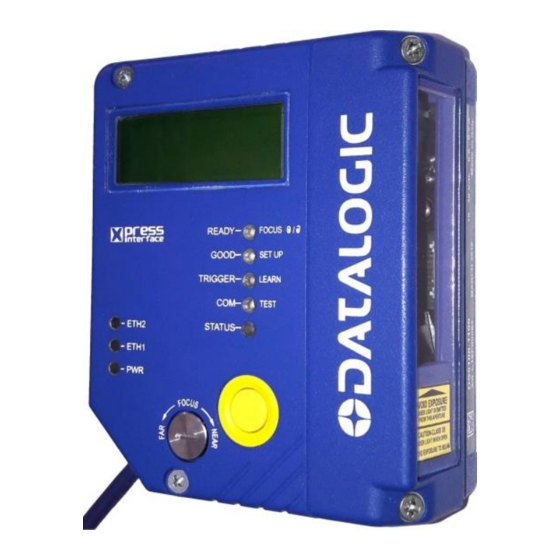
Page 12: General View
GENERAL VIEW DS5100-X200 Serial Models Figure A Warning and Device Class Labels Indicator LEDs Power – Serial Interfaces – I/O Cable Network LEDs with 25-pin D-sub connector Power On LED Laser Beam Output Window Focus Adjustment Screw X-PRESS™ Push Button... - Page 13 DS5100-X300 Built-in Ethernet Models Figure B Warning and Device Class Labels Indicator LEDs Power – Serial Interfaces – I/O Connector Network LEDs Ethernet Connector Power On LED Laser Beam Output Window Focus Adjustment Screw X-PRESS™ Push Button Mounting Holes (7) Display Connector block rotates to 90°...
- Page 14 DS5100-X400 Profinet-IO Models Figure C Warning and Device Class Labels Indicator LEDs Power – Trigger Input Connector Network LEDs Profinet-IO – EBC Network Connectors Power On LED Laser Beam Output Window Focus Adjustment Screw X-PRESS™ Push Button Mounting Holes (7) Display Connector block rotates to 90°...
- Page 15 DS5100-XX20 OM Models Figure D Warning and Device Class Labels Indicator LEDs Power – Serial Interfaces – I/O Cable Network LEDs with 25-pin D-sub connector Power On LED Laser Beam Output Window Focus Adjustment Screw X-PRESS™ Push Button Mounting Holes (7) Display...
- Page 16 DS5100-XX05 Subzero™ Models Figure E Warning and Device Class Labels Indicator LEDs Power – Serial Interfaces – I/O Connector Network LEDs Ethernet Connector Power On LED Laser Beam Output Window w/ heater Focus Adjustment Screw X-PRESS™ Push Button Mounting Holes (7) Subzero™...
-
Page 17: Rapid Configuration
RAPID CONFIGURATION 1 RAPID CONFIGURATION NOTE: This chapter illustrates a Stand Alone application. For other types of installations, such as ID-NET, Fieldbus, Pass-Through layouts, etc., refer to chapters 4, and 5. For complete scanner configuration using the Genius configuration program, refer to the Context-Sensitive Help On-Line. STEP 1 –... - Page 18 DS5100 REFERENCE MANUAL CBX100/500 Pinout for DS5100 The table below gives the pinout of the CBX100/500 terminal block connectors. Use this pinout when the DS5100 reader is connected by means of the CBX100/500: CBX100/500 Terminal Block Connectors Input Power Outputs Power Supply Input Voltage + Power Source - Outputs Power Supply Input Voltage -...
-
Page 19: Step 2 - Mount And Position The Scanner
RAPID CONFIGURATION STEP 2 – MOUNT AND POSITION THE SCANNER DS5100 Standard and Subzero Models 1. To mount the scanner, use the mounting bracket to obtain the most suitable position for the reader as shown in the figures below. Skew Pitch -45°... - Page 20 DS5100 REFERENCE MANUAL DS5100 OM Models 1. To mount the DS5100 OM, use the mounting bracket to obtain the most suitable position for the reader as shown in the figures below. Skew alignment marks -45° -15° 0° 45° 15° Tilt Figure 5 - Positioning with Mounting Bracket 2.
-
Page 21: Step 3 - Focus The Scanner
RAPID CONFIGURATION STEP 3 – FOCUS THE SCANNER The reading distance depends on the focus distance of the scanner and should be set according to the application requirements. The Focus Position is set directly through the focus adjustment screw on the front panel of the scanner. This screw moves the internal lens of the scanner to change the focal point of the scanner. -
Page 22: Step 4 - X-Press Configuration
DS5100 REFERENCE MANUAL STEP 4 – X-PRESS CONFIGURATION X-PRESS is the intuitive Human Machine Interface designed to improve ease of installation and maintenance. Status and diagnostic information are clearly presented by means of the colored LEDs, whereas the single push button gives immediate access to the following relevant functions: ... - Page 23 RAPID CONFIGURATION Auto Learn If you are configuring your scanner using X-PRESS, you must start with the Auto Learn procedure. 1. Enter the Auto Learn function by holding the X-PRESS push button pressed until the LEARN LED is on. 2. Release the button to enter the Auto Learn function. Once entered, the reader starts a procedure to automatically detect and recognize barcodes (by type and length), which are presented to it (*).
- Page 24 DS5100 REFERENCE MANUAL Auto Setup (Optional) At the end of the Auto Learn procedure, you have the possibility to follow the Auto Setup procedure to set up the reading parameters. 1. Enter the Auto Setup function by holding the X-PRESS push button pressed until the SETUP LED is on.
- Page 25 RAPID CONFIGURATION Focus Lock/Unlock You must perform the Focus Lock procedure to save the mechanical focus position to memory. When Locked, if the mechanical focus position is changed by more than the allowed tolerance of the value in memory, a diagnostic alarm will be sent to the display. See par.
- Page 26 DS5100 REFERENCE MANUAL EBC/Profinet-IO Network Selection (only on Profinet-IO dual port models) For on-board Profinet 2 port models, the DS5100 scanner can be configured to work as a Slave in an EBC network. The only way to make this selection is through the X-PRESS button.
-
Page 27: Step 5 - Install Genius Configuration Program
RAPID CONFIGURATION STEP 5 – INSTALL GENIUS CONFIGURATION PROGRAM Genius is a Datalogic scanner configuration tool providing several important advantages: Wizard approach for new users; Multi-language version; Defined configuration directly stored in the reader; Communication protocol independent from the physical interface allowing to consider the reader as a remote object to be configured and monitored. - Page 28 DS5100 REFERENCE MANUAL 1. Select the Create a new configuration button. You will be guided through the configuration being asked to define the following parameters: Barcode selection and definition...
- Page 29 RAPID CONFIGURATION Operating mode selection and definition a. Digital Inputs configuration...
- Page 30 DS5100 REFERENCE MANUAL Digital Outputs configuration Hardware interface selection...
- Page 31 RAPID CONFIGURATION Output data format configuration The On Line operating Mode requires the reader to be connected to an External Trigger/Presence Sensor using I1A and I1B inputs. The Automatic operating mode does not require connection to an external Presence Sensor. When working in this mode the reader is continuously scanning, while the reading phase is activated each time a barcode enters the reader reading zone.
- Page 32 DS5100 REFERENCE MANUAL 2. After defining the parameter values the following window appears allowing to complete the reader configuration as follows: Saving the configuration to disk; Switching to Advanced mode; Sending the configuration to the scanner. 3. After sending the configuration to the 4.
-
Page 33: Step 6 - Test Mode
X-PRESS functions. Use a code suitable to your application to test the system. Alternatively, you can use the Datalogic Test Chart (Code 128). 1. Enter the Test mode function by holding the X-PRESS push button pressed until the TEST LED is on. -
Page 34: Advanced Scanner Configuration
DS5100 REFERENCE MANUAL ADVANCED SCANNER CONFIGURATION The ADVANCED configuration mode (instead of the Wizard) is available when starting the Genius program and is addressed to expert users being able to complete a detailed scanner configuration. By choosing this option it is possible either to start a new scanner configuration or to open and modify an old one. -
Page 35: Introduction
Custom Application If the Standard Application Program does not meet your Programs requirements, please contact your local Datalogic distributor. Some of the main features are listed below: Medium, Long Range, Linear and Oscillating Mirror models, user selectable focus for high application flexibility ... -
Page 36: Indicators
DS5100 REFERENCE MANUAL 2.1.1 Indicators The five LEDs on the side of the scanner (Figure A, B, C, D, E, 7) indicate the following: Color Description This LED indicates the device is ready to operate. For Subzero READY Green models this LED blinks during the warm-up phase. This LED confirms successful reading. - Page 37 INTRODUCTION ID-NET Multidata: Multiple stations – single scanner ID-NET interface allows connection of scanners reading objects placed on independent conveyors. All scanners are typically located far away from each other and they use a dedicated presence sensor. At the end of each reading phase, each scanner transmits its own data message to the host. Thanks to ID-NET, data collection among readers is accomplished at a high speed without the need of an external multiplexing device.
-
Page 38: How To Setup/Configure The Scanner Network
DS5100 REFERENCE MANUAL 2.2.1 How To Setup/Configure the Scanner Network A complete ID-NET scanner network can be rapidly setup, as follows: Mounting & Connection 1. Mechanically mount/install all the readers (refer to par. 3.2 and 3.3). 2. Wire ID-NET (refer to par. 4.3). 3. -
Page 39: X-Press Human Machine Interface
INTRODUCTION 2.3 X-PRESS HUMAN MACHINE INTERFACE X-PRESS is the intuitive Human Machine Interface designed with the precise goal of improving ease of installation and maintenance. Status and diagnostic information are clearly presented by means of five-colored LEDs, whereas the single multi-function key gives immediate access to relevant functions: ... -
Page 40: X-Press Functions
DS5100 REFERENCE MANUAL 2.3.2 X-PRESS Functions Quick access to the following functions is provided by an easy procedure using the push button: 1 – Press the button (the STATUS LED will give a visual feedback). 2 – Hold the button until the specific function LED is on (TEST, LEARN or SETUP). - Page 41 INTRODUCTION AutoLearn Function Once entered, the reader starts a procedure to automatically detect and recognize barcodes (by type and length), which are presented to it . The laser turns on and the LEARN LED blinks to indicate the ongoing process. The procedure is as follows: place the desired barcode on the scanline.
-
Page 42: External Memory Backup & Restore
DS5100 REFERENCE MANUAL Focus Lock/Unlock Once entered, the scanner automatically performs the Focus Lock procedure to save the mechanical focus position to memory. If the mechanical focus position is changed by more than the allowed tolerance of the value in memory, a diagnostic alarm will be sent to the display. - Page 43 INTRODUCTION The Backup & Restore function is supported by the scanner when connected to or through: QL500 (Ethernet TCP/IP) CBX + BM100 and/or BM2x0 QLM-Series Gateways SC4000 ID-NET Controller NOTE: Before executing a Backup on a BM100 backup module make sure the Write Protection switch is set to Unlocked.
- Page 44 DS5100 REFERENCE MANUAL In the pictures above, the Backup/Restore Dialog is shown: the Devices window lists all of the available devices in the current configuration, the Backup Contents window lists any previous device backups. To perform a Backup: 1.
-
Page 45: Automatic Scanner Replacement
INTRODUCTION 2.5 AUTOMATIC SCANNER REPLACEMENT This parameter allows single scanner replacement to take place automatically (at power on time only) whenever a scanner substitution is made. Data for the Automatic Scanner Replacement are stored in the backup memory [BM100 Backup Module or QLMxxx Gateway]. -
Page 46: Display
DS5100 REFERENCE MANUAL 2.6 DISPLAY The DS5100 is equipped with a 2 line by 16 character LCD display which shows various diagnostic, menu and operating mode messages according to a defined priority (0 = top priority): Priority Message Type File Transfer, Backup & Restore, Restore Default Parameters X-PRESS Menu Selection Focus Setup Procedure Diagnostic Alarms *... - Page 47 INTRODUCTION Autolearn Results: X = recognized code symbology. Y = number of digits in the read code Z = number of configured slot (at the end of the procedure this number represents the total slots configured). Diagnostic Alarms: X = expected focus distance in cm and inches X = expected speed Y = actual speed Generic Alarms:...
- Page 48 DS5100 REFERENCE MANUAL Reading Results: A = reading result – Good (Good Read), Part (Partial Read), Mult (Multiple Read) X = code content Y = number of codes read W W W X = code content Y = number of digits in the code DGT = "digits"...
- Page 49 INTRODUCTION Welcome Message: The display alternates between message 1, 2 and 3. Message 1 X = scanner model K = software – STD=Standard, SS=Special Y = software version R = Device Network Type – MUL=Multidata, SYN=Synchronized, ALN=Alone NOTE: For dual port Profinet-IO/EBC models, R = Operating Mode – ONL=On Line, AUT=Automatic,...
-
Page 50: Model Description
DS5100 REFERENCE MANUAL 2.7 MODEL DESCRIPTION DS5100 scanners are described by their model number which indicates the characteristics listed in the diagram below. Not all combinations are available. For a complete list of combinations see the Models tab on the Product page of the website. DS5100 –... -
Page 51: Oscillating Mirror Models
INTRODUCTION 2.8 OSCILLATING MIRROR MODELS The DS5100 OM is completely software controlled and software programmable through Genius which allows adjusting the oscillating frequency and the minimum and maximum oscillation angles of two separate reading zones. When the oscillating mirror is programmed to read barcode labels at small angles, position the reader to assure at least 15°... -
Page 52: Subzero Temperature Models
DS5100 REFERENCE MANUAL 2.9 SUBZERO TEMPERATURE MODELS The DS5100 Subzero scanner is an industrial scanner designed to operate in industrial refrigerator/freezer cells or other stable subzero degree environments, which are below the operating range of standard industrial scanners. It is not designed to move between subzero and normal environments (rapid temperature changes). -
Page 53: Ip Address Alignment Using Genius Discovery
INTRODUCTION 2.10 IP ADDRESS ALIGNMENT USING GENIUS DISCOVERY For Bulit-in Ethernet and Profinet-IO models, the scanner IP address can automatically be found on the Ethernet network by using the Genius Discovery utility available in the Options>Communications tab. NOTE: This feature only works for the built-in interfaces: Ethernet or Profinet-IO. - Page 54 DS5100 REFERENCE MANUAL 3. Click the Apply button. The device will be re-discovered. You should now see the device displayed with the newly assigned IP address.
-
Page 55: Accessories
INTRODUCTION 4. Click OK to return to the Communications folder. You will see the updated IP address in the "Device address or name" field. NOTE: The Port number used to connect to Genius must be 51235 (default). 5. Click OK to return to Genius and perform a Device>Get to connect to the device. 2.11 ACCESSORIES The following accessories are available on request for the DS5100: Name... - Page 56 DS5100 REFERENCE MANUAL Name Description Part Number BM400 DeviceNet Module IP65 93ACC1814 BM500/510/520 Ethernet/IP Module STD/IP65/IP54 93ACC1812, 93ACC1813, 93ACC1840 BM600 CANopen Module 93ACC1815 BM700 Profinet Module 93ACC1816 BM1100 CC-Link Module 93ACC1845 BM1200/1210 Modbus TCP Module 93ACC1848, 93ACC1849 BM1300 EtherCAT IP54 Module 93ACC0113 BA100 DIN Rail Mounting Adapters...
- Page 57 INTRODUCTION Name Description Part Number PG-6001 24 V Power Supply Unit UK 93ACC1719 (for Serial and Ethernet models – connects to CBX) PG-6002 24 V Power Supply Unit US 93ACC1718 (for Serial and Ethernet models – connects to CBX) PG-100-K01 POWER SUPPLY 60W KIT EU 93ACC0059 with M12 connector (for Profinet models)
-
Page 58: Mechanical Installation
DS5100 REFERENCE MANUAL 3 MECHANICAL INSTALLATION 3.1 PACKAGE CONTENTS Verify that the DS5100 reader and all the parts supplied with the equipment are present and intact when opening the packaging; the list of parts includes: DS5100 reader DS5100 Quick Guide ... -
Page 59: Mechanical Installation
MECHANICAL INSTALLATION 3.2 MECHANICAL INSTALLATION DS5100 can be installed to operate in different positions. The four screw holes (M4 x 5mm depth) on the body of the reader are for mechanical fixture to the L-shaped mounting bracket. There are also three screw holes (M5 x 5mm depth) for fixture to the U-shaped mounting bracket. - Page 60 DS5100 REFERENCE MANUAL [in] Connector block rotates to 90° position. Figure 16 – DS5100 Standard Ethernet Model Overall Dimensions...
- Page 61 MECHANICAL INSTALLATION [in] Connector block rotates to 90° position. Figure 17 – DS5100 Standard Profinet Model Overall Dimensions...
- Page 62 DS5100 REFERENCE MANUAL Figure 18 – DS5100 OM Serial Model Overall Dimensions...
- Page 63 MECHANICAL INSTALLATION Connector block rotates to 90° position. Figure 19 – DS5100 OM Ethernet Model Overall Dimensions...
- Page 64 DS5100 REFERENCE MANUAL Connector block rotates to 90° position. Figure 20 – DS5100 OM Profinet Model Overall Dimensions...
- Page 65 MECHANICAL INSTALLATION [0.12] Ø4.2 [Ø0.17] N°4 [0.17] [2.76] Ø8.1 [Ø0.32] N°2 [in] [0.32] N°6 Ø4.2 [Ø0.17] N°4 [2.76] [3.15] Figure 21 – L Shape Mounting Bracket Overall Dimensions [in] Figure 22 – U Shape Mounting Bracket Overall Dimensions...
-
Page 66: Mounting Ds5100
DS5100 REFERENCE MANUAL 3.2.1 Mounting DS5100 Using the DS5100 mounting bracket you can quickly and easily obtain standard mounting positions (i.e. 15° Skew angles) for the reader as shown in the following figures: Skew Pitch -45° -15° 0° 15° 45° Figure 23 –... - Page 67 MECHANICAL INSTALLATION Skew alignment marks -45° -15° 0° 45° 15° Tilt Figure 24 – Positioning with U Shape Mounting Bracket...
- Page 68 DS5100 REFERENCE MANUAL Skew alignment marks -45° -15° 0° 15° 45° Tilt Figure 25 – DS5100 OM Positioning with U Shape Mounting Bracket...
-
Page 69: Mounting Scanner Accessories
MECHANICAL INSTALLATION 3.3 MOUNTING SCANNER ACCESSORIES 3.3.1 Mounting a GFC-40 Accessory Deflection Mirror The GFC-40 is a 105° deflection reading mirror accessory that mounts directly to the DS5100 Scanner. It allows code reading in reduced space applications. The installation of the deflection mirror is very easy. 1. -
Page 70: Positioning
DS5100 REFERENCE MANUAL 3.4 POSITIONING The DS5100 scanner is able to decode moving barcode labels at a variety of angles, however significant angular distortion may degrade reading performance. When mounting the DS5100 take into consideration these three ideal label position angles: Skew 15°... - Page 71 MECHANICAL INSTALLATION The Pitch angle is represented by the value P in Figure 31. Position the reader in order to minimize the Pitch angle. Figure 31 – DS5100 Pitch Angle...
-
Page 72: Electrical Installation
DS5100 REFERENCE MANUAL 4 ELECTRICAL INSTALLATION Serial Interface models are equipped with a cable terminated by a 25-pin male D-sub connector for connection to the power supply and input/output signals. For Ethernet models, an accessory 17-pin to 25-pin cable is available for CBX connections. We recommend making system connections through one of the CBX connection boxes since they offer the advantages of easy connection, easy device replacement and filtered reference signals. -
Page 73: Power Supply
ELECTRICAL INSTALLATION Main Interface RS485 RS232 Full-Duplex *RX+ *RX- SGND SGND * Do not leave floating, see par. 4.2.2 for connection details. NOTE: To avoid electromagnetic interference when the scanner is connected to a CBX connection box, verify the jumper positions in the CBX as indicated in its Installation Manual. -
Page 74: Rs232 Interface
DS5100 REFERENCE MANUAL 4.2.1 RS232 Interface The serial interface is used in this case for point-to-point connections; it handles communication with the host computer and allows both transmission of code data and the programming of the scanner. This is the default setting. The following pins are used for RS232 interface connection: CBX100/500 Function... -
Page 75: Rs485 Full-Duplex Interface
ELECTRICAL INSTALLATION 4.2.2 RS485 Full-Duplex Interface The RS485 full-duplex (5 wires + shield) interface is used for non-polled communication protocols in point-to-point connections over longer distances (max 1200 m / 3940 ft) than those acceptable for RS232 communications or in electrically noisy environments. The CBX pinout follows: CBX100/500 Function... -
Page 76: Id-Net Interface
1200 m 900 m 700 m * Application dependent, contact your Datalogic Automation representative for details. NOTE: The default ID-NET baudrate is 500 kbps. Lower ID-NET baudrates allow longer cable lengths. The baudrate is software configurable by authorized Datalogic Automation personnel only. -
Page 77: Id-Net Response Time
ELECTRICAL INSTALLATION 4.3.2 ID-NET Response Time The following figure shows the response time of the ID-NET network. This time is defined as the period between the Trigger activation and the beginning of data transmission to the Host. Max ID-NET Response Time 14 15 Number of Nodes 500 kbps... - Page 78 DS5100 REFERENCE MANUAL Figure 38 – ID-NET Network Connections with isolated power blocks...
- Page 79 ELECTRICAL INSTALLATION Figure 39 - ID-NET Network Connections with Common Power Branch Network...
- Page 80 DS5100 REFERENCE MANUAL Figure 40 – ID-NET Network Connections with Common Power Star Network...
-
Page 81: Id-Net Network Termination
ELECTRICAL INSTALLATION 4.3.3 ID-NET Network Termination The network must be properly terminated in the first and last scanner of the network. This is done by setting the ID-NET Termination Resistance Switch in the CBX100/500 to ON. 4.4 AUXILIARY RS232 INTERFACE The auxiliary serial interface is used exclusively for RS232 point-to-point connections. -
Page 82: Inputs
DS5100 REFERENCE MANUAL 4.5 INPUTS There are two optocoupled polarity insensitive inputs available on the scanner: Input 1 (External Trigger) and Input 2, a generic input: The electrical features of both inputs are: Maximum voltage: 30 Vdc Maximum current: 12 mA (scanner) + 12 mA (CBX) An anti-disturbance filter is implemented in software on both inputs so that the minimum pulse duration is ... - Page 83 ELECTRICAL INSTALLATION NPN Photocell Power to Input Photocell Signal Photocell Reference Figure 44 - NPN External Trigger Using Scanner Power EXTERNAL TRIGGER INPUT CONNECTIONS USING EXTERNAL POWER PNP Photocell Input Signal Pulled down to External Input Device Reference Figure 45 - PNP External Trigger Using External Power NPN Photocell Pulled up to External Input Device Power...
- Page 84 DS5100 REFERENCE MANUAL CBX100/500 Function Power Source - Inputs Input 2 A (polarity insensitive) Input 2 B (polarity insensitive) Power Reference - Inputs INPUT 2 CONNECTIONS USING SCANNER POWER Input Device Power to Input Device Input Input Device Signal Reference PNP Input 2 Using Scanner Power Input Device Power to...
-
Page 85: Code Verifier
ELECTRICAL INSTALLATION Input Device Pulled up to External Input Device Power Input Signal Figure 48 - NPN Input 2 Using External Power 4.5.1 Code Verifier If the scanner is used as a Code Verifier, the verifier code can be configured in software through the Genius configuration program. - Page 86 DS5100 REFERENCE MANUAL The output signals are fully programmable being determined by the configured Activation/Deactivation events, Deactivation Timeout or a combination of the two. The electrical features of the outputs are the following: = 30 Vdc max. = 40 mA continuous max.; 130 mA pulsed max. = 1 Vdc max.
-
Page 87: User Interface - Host
ELECTRICAL INSTALLATION OUTPUT 1 AND 2 CONNECTIONS USING EXTERNAL POWER Output 1 Device Output 2 Device Pulled up to External Pulled up to External Output Device Power Output Device Power Output Output Signal Signal Figure 51 - PNP/Output Open Emitter Using External Power Output 1 Device Output 2 Device Output... -
Page 88: Typical Layouts
DS5100 REFERENCE MANUAL 5 TYPICAL LAYOUTS The following typical layouts refer to system hardware configurations. Dotted lines in the figures refer to optional hardware configurations within the particular layout. These layouts also require the correct setup of the software configuration parameters. Complete software configuration procedures can be found in the Guide To Rapid Configuration in the Genius Help On Line. -
Page 89: External Fieldbus Using Host Mode Interface Modules
TYPICAL LAYOUTS 5.2 EXTERNAL FIELDBUS USING HOST MODE INTERFACE MODULES In this layout a single scanner functions as a Slave node on a Fieldbus network. The data is transmitted to the Host through an accessory Fieldbus interface board installed inside the CBX500 connection box. -
Page 90: Built-In Ethernet Networks
DS5100 REFERENCE MANUAL 5.3 BUILT-IN ETHERNET NETWORKS 5.3.1 External Trigger Ethernet Host (x3xx models only) In this layout, before proceeding with the connection, it is necessary to configure the reader Ethernet parameters via Genius. For further details see par. 2.10. When using a Local Area Network (LAN), one or more DS5100-x3xx model scanners can be connected to the network by using CAB-ETH-M0x cables. -
Page 91: Built-In Profinet-Io Networks
TYPICAL LAYOUTS 5.4 BUILT-IN PROFINET-IO NETWORKS The PROFINET-IO interface is used to collect data from several readers to build a multi-point or a multi-sided reading system; there can be one PROFINET-IO Controller (Host) and up to 255 PROFINET-IO Devices (Scanners) connected together in the same subnetwork. Before proceeding with the connection, it is necessary to configure the scanner. -
Page 92: Single Station Layout With Dual Port Scanners
DS5100 REFERENCE MANUAL 5.4.2 Single Station Layout with Dual Port Scanners (x4xx models) More than one DS5100-x4xx (dual port) model scanner is chained together in the PROFINET-IO network by using an ETH CABLE M12-M12 cable. The first scanner in the chain is connected to a Certified PROFINET-IO Switch or PLC using a CAB-ETH-M0x cable. -
Page 93: Multi Station Layout With Dual Port Scanners
TYPICAL LAYOUTS 5.4.3 Multi Station Layout with Dual Port Scanners (x4xx models only) More than one DS5100-x4xx (dual port) model scanner is chained together in the PROFINET-IO network by using an ETH CABLE M12-M12 cable. The first scanner in the chain is connected to a Certified PROFINET-IO Switch or PLC using a CAB-ETH-M0x cable. -
Page 94: Ebc™ Networks
DS5100 REFERENCE MANUAL 5.5 EBC™ NETWORKS (x4xx models only) The DS5100 dual port model can be integrated into a Large Synchronized Network (multi- scanner reading station) using the proprietary EBC network interface. The SC5000 (Controller) is the station master and the DS5100 and/or DS8110/DX8210 EBC slave scanners are connected together in the same subnetwork. - Page 95 TYPICAL LAYOUTS DS5100-x4xx models can only be integrated into EBC networks as slave scanners where SC5000 is the Master Controller. To do this: 1. Physically mount and electrically connect the DS5100 scanner in the application. 2. To set the DS5100 scanner as an EBC Slave, follow the EBC network selection procedure described in step 4, X-PRESS Configuration.
- Page 96 DS5100 REFERENCE MANUAL 4. Give a descriptive name to the DS5100 scanner (typically scanner position) and then press the Update All button. 5. From the SC5000 Utilities menu launch Genius. 6. Run the Get command to open the DS5100 Controller.
- Page 97 TYPICAL LAYOUTS 7. Double-click on the DS5100 scanner to configure it.
- Page 98 DS5100 REFERENCE MANUAL Common parameters to configure/check are: Code Settings Operating Mode: PackTrack (default) or On Line, etc. Focus Lock NOTE: The PackTrack operating mode is only available for dual port long range models working in EBC (DS5100-24xx). 8.
-
Page 99: Id-Net Synchronized Networks
TYPICAL LAYOUTS 5.6 ID-NET SYNCHRONIZED NETWORKS The ID-NET connection is used to collect data from several scanners to build a multi-point or a multi-sided reading system; there can be one master and up to 31 slaves connected together. The slave scanners are connected together using the ID-NET interface. Every slave scanner must have a ID-NET address in the range 1-31. - Page 100 DS5100 REFERENCE MANUAL NOTE: The auxiliary serial interface of the slave scanners can be used in Local Echo communication mode to control any single scanner (visualize collected data) or to configure it using the Genius utility or the Genius based Host Mode programming procedure.
- Page 101 TYPICAL LAYOUTS The Master scanner can communicate to the Host as a Slave node on an Ethernet TCP/IP network. This example requires using the accessory BM2x0 Ethernet interface board installed inside the CBX500 connection box. System configuration can be accomplished through the Auxiliary interface of the Master scanner (internal CBX500 9-pin connector) using the Genius configuration program or Genius based Host Mode programming.
- Page 102 DS5100 REFERENCE MANUAL Alternatively, the Master scanner can communicate to the Host as a Slave node on a Fieldbus network. This requires using an accessory Fieldbus interface board installed inside the CBX500 connection box. System configuration can be accomplished through the Auxiliary interface of the Master scanner (internal CBX500 9-pin connector) using the Genius configuration program or Genius based Host Mode programming.
- Page 103 TYPICAL LAYOUTS The QLM600 Profibus Gateway active connection module can also be used. System configuration can be accomplished through the Auxiliary interface of the Master scanner (QLM600 Aux connector) using the Genius configuration program or Genius based Host Mode programming. QL100 Configuration PC CBL-1490...
-
Page 104: Id-Net Multidata Networks
DS5100 REFERENCE MANUAL 5.7 ID-NET MULTIDATA NETWORKS For a Master/Slave Multidata layout each scanner has its own reading phase independent from the others; each single message is sent from the master scanner to the Host computer. Master Slave#1 Slave#n Terminal Power ... -
Page 105: Pass-Through
TYPICAL LAYOUTS 5.8 PASS-THROUGH An alternative Pass-Through layout allows the more efficient ID-NET network to be used. This layout is really an ID-NET Master/Slave Multidata layout which also allows each scanner (Master and Slaves) to accept input on the Auxiliary interface, for example to connect a device such as a hand-held reader for manual code reading capability. -
Page 106: Reading Features
DS5100 REFERENCE MANUAL 6 READING FEATURES 6.1 ADVANCED CODE RECONSTRUCTION (ACR 4) The traditional way of barcode reading could be called “Linear Reading”. In this case, the laser beam crosses the barcode symbol from its beginning to its end as shown in the following figure: Laser Beam Figure 69 –... -
Page 107: Tilt Angle For Advanced Code Reconstruction
READING FEATURES 6.1.1 Tilt Angle for Advanced Code Reconstruction The most important parameter in Advanced Code Reconstruction is the value of the maximum tilt angle (maximum) under which the code reconstruction process is still possible. Laser Beam 0° to ... -
Page 108: Acr Reading Conditions For Medium Range Models
DS5100 REFERENCE MANUAL 6.1.2 ACR Reading Conditions for Medium Range Models The following tables describe the minimum code height requirements (in mm) for standard ACR4 applications depending on the code symbology and the given reading conditions. ANSI Grade B minimum 2/5 Interleaved Minimum Code Height for ACR4 Reading (mm) 45°... - Page 109 READING FEATURES Codabar Minimum Code Height for ACR4 Reading (mm) 45° max 30° max Conveyor Speed (m/s) 0.25 0.30 0.33 Code Resolution 0.38 (mm) 0.50 0.72 1.00 Ratio 3:1; Interdigit = Module Size Table 4 EAN 8-13, UPC-A Minimum Code Height for ACR4 Reading (mm) 45°...
-
Page 110: Acr Reading Conditions For Long Range Models
DS5100 REFERENCE MANUAL 6.1.3 ACR Reading Conditions for Long Range Models The following tables describe the minimum code height requirements (in mm) for standard ACR4 applications depending on the code symbology and the given reading conditions. ANSI Grade B minimum 2/5 Interleaved Minimum Code Height for ACR4 Reading (mm) 45°... - Page 111 READING FEATURES Codabar Minimum Code Height for ACR4 Reading (mm) 45° max 30° max Conveyor Speed (m/s) 0.25 0.30 0.33 Code Resolution 0.38 (mm) 0.50 0.72 1.00 Ratio 3:1; Interdigit = Module Size Table 9 EAN 8-13, UPC-A Minimum Code Height for ACR4 Reading (mm) 45°...
-
Page 112: Linear Code Reading
DS5100 REFERENCE MANUAL 6.2 LINEAR CODE READING The number of scans performed on the code by the scanner and therefore the decoding capability is influenced by the following parameters: number of scans per second code motion speed label dimensions ... -
Page 113: Picket-Fence Mode
READING FEATURES 6.2.2 Picket-Fence Mode If scanning is parallel to the code motion, (Figure 75), the number of effective scans is given by the following formula: SN = [((FW-LW)/LS) * SS] -2 Where: SN = number of effective scans FW = reading field width (in mm) LW = label width (in mm) LS = label movement speed (in mm/s) SS = scans per second... -
Page 114: Performance
DS5100 REFERENCE MANUAL 6.3 PERFORMANCE The reading performance of the DS5100 scanner depends in part on the focus position setting. 1x00 (Linear Medium Range Models) Focus Max Code Resolution Reading Distance on 0.50 mm (20 mils) codes F = 30 Near 0.20 mm (8 mils) 20 cm (7.9 in) - 50 cm (19.7 in) F = 40 Med... - Page 115 READING FEATURES Refer to the diagrams in par. 6.4 for further details on the reading features. For Standard and OM models, these diagrams are taken on various resolution sample codes at a 25 C ambient temperature and depend on the conditions listed under each diagram. Subzero model diagrams are based on an ambient temperature of -35 °C and depend on the conditions listed under each diagram.
-
Page 116: Reading Diagrams
DS5100 REFERENCE MANUAL 6.4 READING DIAGRAMS 6.4.1 Linear Medium Range Models Reading Distance NOTE: (0,0) is the center of the laser beam output window. CONDITIONS Hardware Settings Code Symbology Code 128 0.90 "Pitch" angle 0 "Skew" angle 15 "Tilt" angle 0... - Page 117 READING FEATURES Reading Distance NOTE: (0,0) is the center of the laser beam output window. CONDITIONS Hardware Settings Code Symbology Code 128 0.90 "Pitch" angle 0 "Skew" angle 15 "Tilt" angle 0 Software Parameters Reading Mode Linear For Tilt angles of 45°, the reading performance is reduced by approximately 10%.
- Page 118 DS5100 REFERENCE MANUAL Reading Distance NOTE: (0,0) is the center of the laser beam output window. CONDITIONS Hardware Settings Code Symbology Code 128 0.90 "Pitch" angle 0 "Skew" angle 15 "Tilt" angle 0 Software Parameters Reading Mode Linear For Tilt angles of 45°, the reading performance is reduced by approximately 10%.
- Page 119 READING FEATURES Reading Distance NOTE: (0,0) is the center of the laser beam output window. CONDITIONS Hardware Settings Code Symbology Code 128 0.90 "Pitch" angle 0 "Skew" angle 15 "Tilt" angle 0 Software Parameters Reading Mode Linear For Tilt angles of 45°, the reading performance is reduced by approximately 10%.
- Page 120 DS5100 REFERENCE MANUAL Reading Distance NOTE: (0,0) is the center of the laser beam output window. CONDITIONS Hardware Settings Code Symbology Code 128 0.90 "Pitch" angle 0 "Skew" angle 15 "Tilt" angle 0 Software Parameters Reading Mode Linear For Tilt angles of 45°, the reading performance is reduced by approximately 10%.
-
Page 121: Linear Medium Range Subzero Models
READING FEATURES 6.4.2 Linear Medium Range Subzero Models Reading Distance NOTE: (0,0) is the center of the laser beam output window. CONDITIONS Hardware Settings Code Symbology Code 128 0.90 "Pitch" angle 0 "Skew" angle 15 "Tilt" angle 0 Software Parameters Reading Mode Linear For Tilt angles of 45°, the reading performance is reduced by approximately 10%. - Page 122 DS5100 REFERENCE MANUAL Reading Distance NOTE: (0,0) is the center of the laser beam output window. CONDITIONS Hardware Settings Code Symbology Code 128 0.90 "Pitch" angle 0 "Skew" angle 15 "Tilt" angle 0 Software Parameters Reading Mode Linear For Tilt angles of 45°, the reading performance is reduced by approximately 10%.
- Page 123 READING FEATURES Reading Distance NOTE: (0,0) is the center of the laser beam output window. CONDITIONS Hardware Settings Code Symbology Code 128 0.90 "Pitch" angle 0 "Skew" angle 15 "Tilt" angle 0 Software Parameters Reading Mode Linear For Tilt angles of 45°, the reading performance is reduced by approximately 10%.
- Page 124 DS5100 REFERENCE MANUAL Reading Distance NOTE: (0,0) is the center of the laser beam output window. CONDITIONS Hardware Settings Code Symbology Code 128 0.90 "Pitch" angle 0 "Skew" angle 15 "Tilt" angle 0 Software Parameters Reading Mode Linear For Tilt angles of 45°, the reading performance is reduced by approximately 10%.
- Page 125 READING FEATURES Reading Distance NOTE: (0,0) is the center of the laser beam output window. CONDITIONS Hardware Settings Code Symbology Code 128 0.90 "Pitch" angle 0 "Skew" angle 15 "Tilt" angle 0 Software Parameters Reading Mode Linear For Tilt angles of 45°, the reading performance is reduced by approximately 10%.
-
Page 126: Linear Long Range Models
DS5100 REFERENCE MANUAL 6.4.3 Linear Long Range Models Reading Distance NOTE: (0,0) is the center of the laser beam output window. CONDITIONS Hardware Settings Code Symbology Code 128 0.90 "Pitch" angle 0 "Skew" angle 15 "Tilt" angle ±45 Software Parameters Reading Mode Linear... - Page 127 READING FEATURES Reading Distance NOTE: (0,0) is the center of the laser beam output window. CONDITIONS Hardware Settings Code Symbology Code 128 0.90 "Pitch" angle 0 "Skew" angle 15 "Tilt" angle ±45 Software Parameters Reading Mode Linear...
- Page 128 DS5100 REFERENCE MANUAL Reading Distance NOTE: (0,0) is the center of the laser beam output window. CONDITIONS Hardware Settings Code Symbology Code 128 0.90 "Pitch" angle 0 "Skew" angle 15 "Tilt" angle ±45 Software Parameters Reading Mode Linear...
- Page 129 READING FEATURES Reading Distance NOTE: (0,0) is the center of the laser beam output window. CONDITIONS Hardware Settings Code Symbology Code 128 0.90 "Pitch" angle 0 "Skew" angle 15 "Tilt" angle ±45 Software Parameters Reading Mode Linear...
-
Page 130: Oscillating Mirror Medium Range Models
DS5100 REFERENCE MANUAL 6.4.4 Oscillating Mirror Medium Range Models Reading Distance NOTE: (0,0) is the center of the laser beam output window. CONDITIONS Hardware Settings Code Symbology Code 128 0.90 "Pitch" angle 0 "Skew" angle 15 "Tilt" angle 0 Software Parameters Reading Mode Linear For Tilt angles of 45°, the reading performance is reduced by approximately 10%. - Page 131 READING FEATURES Reading Distance NOTE: (0,0) is the center of the laser beam output window. CONDITIONS Hardware Settings Code Symbology Code 128 0.90 "Pitch" angle 0 "Skew" angle 15 "Tilt" angle 0 Software Parameters Reading Mode Linear For Tilt angles of 45°, the reading performance is reduced by approximately 10%.
- Page 132 DS5100 REFERENCE MANUAL Reading Distance NOTE: (0,0) is the center of the laser beam output window. CONDITIONS Hardware Settings Code Symbology Code 128 0.90 "Pitch" angle 0 "Skew" angle 15 "Tilt" angle 0 Software Parameters Reading Mode Linear For Tilt angles of 45°, the reading performance is reduced by approximately 10%.
- Page 133 READING FEATURES Reading Distance NOTE: (0,0) is the center of the laser beam output window. CONDITIONS Hardware Settings Code Symbology Code 128 0.90 "Pitch" angle 0 "Skew" angle 15 "Tilt" angle 0 Software Parameters Reading Mode Linear For Tilt angles of 45°, the reading performance is reduced by approximately 10%.
- Page 134 DS5100 REFERENCE MANUAL Reading Distance NOTE: (0,0) is the center of the laser beam output window. CONDITIONS Hardware Settings Code Symbology Code 128 0.90 "Pitch" angle 0 "Skew" angle 15 "Tilt" angle 0 Software Parameters Reading Mode Linear For Tilt angles of 45°, the reading performance is reduced by approximately 10%.
-
Page 135: Oscillating Mirror Medium Range Subzero Models
READING FEATURES 6.4.5 Oscillating Mirror Medium Range Subzero Models Reading Distance NOTE: (0,0) is the center of the laser beam output window. CONDITIONS Hardware Settings Code Symbology Code 128 0.90 "Pitch" angle 0 "Skew" angle 15 "Tilt" angle 0 Software Parameters Reading Mode Linear For Tilt angles of 45°, the reading performance is reduced by approximately 10%. - Page 136 DS5100 REFERENCE MANUAL Reading Distance NOTE: (0,0) is the center of the laser beam output window. CONDITIONS Hardware Settings Code Symbology Code 128 0.90 "Pitch" angle 0 "Skew" angle 15 "Tilt" angle 0 Software Parameters Reading Mode Linear For Tilt angles of 45°, the reading performance is reduced by approximately 10%.
- Page 137 READING FEATURES Reading Distance NOTE: (0,0) is the center of the laser beam output window. CONDITIONS Hardware Settings Code Symbology Code 128 0.90 "Pitch" angle 0 "Skew" angle 15 "Tilt" angle 0 Software Parameters Reading Mode Linear For Tilt angles of 45°, the reading performance is reduced by approximately 10%.
- Page 138 DS5100 REFERENCE MANUAL Reading Distance NOTE: (0,0) is the center of the laser beam output window. CONDITIONS Hardware Settings Code Symbology Code 128 0.90 "Pitch" angle 0 "Skew" angle 15 "Tilt" angle 0 Software Parameters Reading Mode Linear For Tilt angles of 45°, the reading performance is reduced by approximately 10%.
- Page 139 READING FEATURES Reading Distance NOTE: (0,0) is the center of the laser beam output window. CONDITIONS Hardware Settings Code Symbology Code 128 0.90 "Pitch" angle 0 "Skew" angle 15 "Tilt" angle 0 Software Parameters Reading Mode Linear For Tilt angles of 45°, the reading performance is reduced by approximately 10%.
-
Page 140: Oscillating Mirror Long Range Models
DS5100 REFERENCE MANUAL 6.4.6 Oscillating Mirror Long Range Models Reading Distance NOTE: (0,0) is the center of the laser beam output window. CONDITIONS Hardware Settings Code Symbology Code 128 0.90 "Pitch" angle 0 "Skew" angle 15 "Tilt" angle ±45 Software Parameters Reading Mode Linear... - Page 141 READING FEATURES Reading Distance NOTE: (0,0) is the center of the laser beam output window. CONDITIONS Hardware Settings Code Symbology Code 128 0.90 "Pitch" angle 0 "Skew" angle 15 "Tilt" angle ±45 Software Parameters Reading Mode Linear...
- Page 142 DS5100 REFERENCE MANUAL Reading Distance NOTE: (0,0) is the center of the laser beam output window. CONDITIONS Hardware Settings Code Symbology Code 128 0.90 "Pitch" angle 0 "Skew" angle 15 "Tilt" angle ±45 Software Parameters Reading Mode Linear...
- Page 143 READING FEATURES Reading Distance NOTE: (0,0) is the center of the laser beam output window. CONDITIONS Hardware Settings Code Symbology Code 128 0.90 "Pitch" angle 0 "Skew" angle 15 "Tilt" angle ±45 Software Parameters Reading Mode Linear...
-
Page 144: Maintenance
DS5100 REFERENCE MANUAL 7 MAINTENANCE 7.1 CLEANING Clean the laser beam output window periodically for continued correct operation of the reader. Dust, dirt, etc. on the window may alter the reading performance. Repeat the operation frequently in particularly dirty environments. Use soft material and alcohol to clean the window and avoid any abrasive substances. -
Page 145: Troubleshooting
Help/Parameters Help/5K Software Configuration Parameters Guide from the command menu. If you’re unable to fix the problem and you’re going to contact your local Datalogic office or Datalogic Partner or ARC, we suggest providing (if possible) the Device Configuration files (*.ddc). - Page 146 DS5100 REFERENCE MANUAL TROUBLESHOOTING GUIDE Problem Suggestions Power On: Is power connected? the “Power If using a power adapter (like PG 6000), is it connected to a wall On”/”Ready” LED is not outlet? If using rail power, does rail have power? If using CBX100, does it have power (check switch and LED)? Measure voltage either at pin 13 and pin 25 (for 25-pin connector) or at spring clamp Vdc and GND (for CBX).
- Page 147 Also check the Code Field Length and Fill Character values. Are the COM port parameters correctly assigned? Communication: Contact your local Datalogic office or Datalogic Partner or Always returns the ARC, because either a Motor or Laser failure has occurred. Reader Failure Note the exact model and Serial Number of the device.
-
Page 148: Technical Features
DS5100 REFERENCE MANUAL 9 TECHNICAL FEATURES ELECTRICAL FEATURES Input Power Supply Voltage 10 - 30 Vdc; (24 Vdc ± 10% for Subzero models) Maximum Consumption xx00 (Standard) 0.6 - 0.2 A; 6 W xx20 (OM) 0.75 - 0.25 A; 7.5 W xx05 (Subzero) 1.2 A;... - Page 149 TECHNICAL FEATURES PHYSICAL FEATURES Standard Models OM Models Mechanical Dimensions 85 x 101 x 42 mm (3.3 x 4 x 1.7 in) 124 x 117 x 48 mm (4.9 x 4.6 x 1.9 in) 104 x 101 x 42 (4.1 x 4 x 1.7) ETH 0°...
-
Page 150: Aalternative Connections For Serial Models
DS5100 REFERENCE MANUAL A ALTERNATIVE CONNECTIONS FOR SERIAL MODELS The connector pinouts and notes given in this appendix are for custom cabling applications. POWER, COM AND I/O CONNECTOR The scanner is equipped with a cable ending in a 25-pin male D-sub connector for connection to the power supply, serial interfaces and input/output signals. -
Page 151: Id-Net Network Termination
ALTERNATIVE CONNECTIONS FOR SERIAL MODELS ID-NET NETWORK TERMINATION The network must be properly terminated by a 120 Ohm resistor at the first and last reader of the network. INPUTS There are two optocoupled polarity insensitive inputs available on the 25-pin D-sub connector of the reader: Input 1 (External Trigger) and Input 2, a generic input. -
Page 152: Outputs
DS5100 REFERENCE MANUAL OUTPUTS Two general purpose optocoupled but polarity sensitive outputs are available on the 25-pin D-sub connector. The pinout is the following: Name Function Configurable digital output 1 + Configurable digital output 1 - Configurable digital output 2 + Configurable digital output 2 - The electrical features of the two outputs are the following: max = 30 Vdc... -
Page 153: User Interface - Serial Host
ALTERNATIVE CONNECTIONS FOR SERIAL MODELS USER INTERFACE - SERIAL HOST RS232 PC-side connections 25-pin male connector 9-pin male connector Name Name How To Build A Simple Interface Test Cable: The following wiring diagram shows a simple test cable including power, external (push- button) trigger and PC RS232 COM port connections. -
Page 154: Balternative Connections For Ethernet Models
DS5100 REFERENCE MANUAL B ALTERNATIVE CONNECTIONS FOR ETHERNET MODELS The connector pinouts and notes given in this appendix are for custom cabling applications. POWER, COM AND I/O CONNECTOR The scanner is equipped with an M12 17-pin male connector for connection to the power supply, serial interfaces and input/output signals. -
Page 155: On-Board Ethernet Connector
ALTERNATIVE CONNECTIONS FOR ETHERNET MODELS ON-BOARD ETHERNET CONNECTOR A Standard M12 D-Coded female connector is provided for the on-board Ethernet connection. This interface is IEEE 802.3 10 BaseT and IEEE 802.3u 100 BaseTx compliant. Use Cat 5e or superior cables. Figure 82 - M12 D-Coded Female Ethernet Network Connector On-Board Ethernet Network Connector Pinout Name... -
Page 156: Outputs
DS5100 REFERENCE MANUAL SCANNER PNP PH-1 wires (brown) +10-30 Vdc (black) NO (blue) 0 V Figure 83 - PH-1 Photocell (PNP) External Trigger Using Scanner Power OUTPUTS Two general purpose non opto-isolated but short circuit protected outputs are available on the M12 17-pin connector. - Page 157 ALTERNATIVE CONNECTIONS FOR ETHERNET MODELS Scanner USER INTERFACE Vext Figure 85 - NPN Output Connection CAUTION: For NPN output connections, the external interface voltage (Vext) must not exceed the scanner power supply source voltage (Vdc) otherwise correct output functioning cannot be guaranteed.
-
Page 158: Cconnections For Profinet-Io Models
DS5100 REFERENCE MANUAL C CONNECTIONS FOR PROFINET-IO MODELS ON-BOARD PROFINET-IO CONNECTORS (2) Two Standard M12 D-Coded female connectors are provided for the on-board PROFINET-IO connection. This interface is IEEE 802.3u 100 BaseTx compliant. Use accessory ETH CABLE M12-M12 cables or Cat 5e or superior cables. Figure 86 - M12 D-Coded 4-pin Female PROFINET-IO Network Connector On-Board Ethernet Network Connector Pinout Name... -
Page 159: Glossary
This organization (a service of the Food and Drug Administration) is responsible for the safety regulations governing acceptable limitations on electronic radiation from laser devices. Datalogic devices are in compliance with the CDRH regulations. Code Positioning Variation in code placement that affects the ability of a scanner to read a code. The terms Pitch, Skew, and Tilt deal with the angular variations of code positioning in the X, Y and Z axes. - Page 160 Full Duplex Simultaneous, two-way, independent transmission in both directions. Host A computer that serves other terminals in a network, providing services such as network control, database access, special programs, supervisory programs, or programming languages. Interface A shared boundary defined by common physical interconnection characteristics, signal characteristics and meanings of interchanged signals.
- Page 161 Serial Port An I/O port used to connect a scanner to your computer, identifiable by a 9-pin or 25-pin connector. Signal An impulse or fluctuating electrical quantity (i.e.: a voltage or current) the variations of which represent changes in information. Skew Rotation about the Y-axis.
-
Page 162: Index
INDEX ID-NET Network Termination, 65, 135, 139 ID-NET Response Time, 61 ID-NET Synchronized Networks, 83 Accessories, 39 Inputs, 66, 135, 139 ACR 4, 90 IP Address Alignment Using Genius Discovery, Alternative Connections for Ethernet Models, Alternative Connections for Serial Models, 134 Automatic Scanner Replacement, 29 Auxiliary RS232 Interface, 65 Laser Safety, vii... - Page 163 X-PRESS Human Machine Interface, 23...
Need help?
Do you have a question about the DS5100-X200 and is the answer not in the manual?
Questions and answers