Table of Contents
Advertisement
Quick Links
Instruction Manual
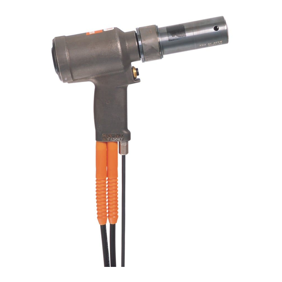
2620, A2620, 2620-PT, and A2620-PT
Hydraulic Installation Tools
EC Declaration of Conformity
November 8,2017
HK1012
Description
Components Drawings
and Parts Lists
Kits and Accessories
Makers of Huck
, Marson
, Recoil
®
®
Brand Fasteners, Tools & Accessories
2
3-4
5
5
6
7
8
9-10
10
10
11
12-13
14-18
19
20
®
Advertisement
Table of Contents

Subscribe to Our Youtube Channel
Related Manuals for Huck 2620


Summary of Contents for Huck 2620
-
Page 1: Table Of Contents
EC Declaration of Conformity Safety Instructions Description Specifications Principle of Operation Instruction Manual Preparation for Use 2620, A2620, 2620-PT, and A2620-PT Operating Instructions Hydraulic Installation Tools Maintenance 9-10 Hydraulic Couplings Sticker Locations Disassembly Assembly 12-13 Components Drawings and Parts Lists... - Page 2 2620 series Hydraulic Installation Tools (HK1012)
-
Page 3: Safety Instructions
3. Be aware that failure of the workpiece, accessories, equipment. or the inserted tool itself can generate high velocity 2. Huck equipment must be maintained in a safe working projectiles. condition at all times. Tools and hoses should be 4. Always wear impact resistant eye protection during tool inspected at the beginning of each shift/day for operation. - Page 4 2620 series Hydraulic Installation Tools (HK1012) Safety Instructions (continued) IV. REPETITIVE MOTION HAZARDS: instructions and as required by occupational health and 1. When using assembly power tool, the operator can safety regulations. experience discomfort in the hands, arms, shoulders, 4. Operate and maintain tool as recommended in the neck or other parts of the body.
-
Page 5: Specifications
Hydraulic Unit ® MAX FLOW RATE: HOSE KITS: 2 gpm (7.5 l/m) Use only genuine HUCK Hose Kits rated @ 10,000 psi (689.5 bar) working pressure. MAX PULL PRESSURE: 7400 psi (510 bar) HYDRAULIC FLUID: Hydraulic fluid shall meet DEXRON ®... -
Page 6: Principle Of Operation
2620 series Hydraulic Installation Tools (HK1012) Principle of Operation Figure 1a Figure 1b Piston Travel Piston Travel PULL PISTON PINTAIL EJECTOR DUMP VALVE TRIGGER SWITCH HYDRAULIC HOSES Pressurized Oil RETURN PRESSURE RETURN PRESSURE PULL PRESSURE PULL PRESSURE Return Oil PULL PRESSURE... -
Page 7: Preparation For Use
2620 series Hydraulic Installation Tools (HK1012) Preparation for Use WARNING: Huck recommends that a Huck WARNINGS: POWERIG be used to power Huck tools. ® - Read entire manual before using tool. (Only use the POWERIG as indicated in - A 30-minute training session with its instruction manual.) Hydraulic power... -
Page 8: Operating Instructions
2620 series Hydraulic Installation Tools (HK1012) Operating Instructions TO INSTALL A HUCKBOLT® FASTENER: WARNINGS: - Wear approved eye and hearing CAUTION: Remove the excess gap from protection. between the sheets to ensure that enough - Ensure adequate clearance for operator’s of the pintail emerges from the collar hands before installing fasteners. -
Page 9: Maintenance
2620-PTKIT) should be kept on hand. Follow the disassembly and assembly procedures in Inspect cylinder bore, piston, piston rod, and unloading this manual. If Huck recommended procedures are not valve for scored surfaces, excessive wear, and damage; followed, the tool could be damaged. -
Page 10: Hydraulic Couplings
Figure 14 Sticker Locations The 2620 series tools are labeled with stickers that contain safety and pressure-settings information. These stickers must remain on the tool and be legible. Any sticker that becomes damaged or worn, or has been removed from the tool, or when replacing the cylinder, MUST be ordered and placed in the location shown below. -
Page 11: Disassembly
NOTE: Complete step 5 only if the switch, wire, or connector is to be repaired. 5. Models 2620 & 2620-PT: Remove the retaining nut and locking ferrule from the strain relief. Loosen the setscrew and remove the switch. Loosen and remove the two wires from the switch. -
Page 12: Assembly
7. Thread the GLYD Ring Insertion Tool (P/N 121694- jaw vise and install the assembled Ejector Gland. Use 2620) into the back of the cylinder. (Figure 6) Hex Key (P/N 122048) to tighten. (Figures 4, 8, & 8. Use a press to carefully push piston and front gland assembly into the back of the cylinder. - Page 13 If removed, reinstall the electrical/air connector NOTE: If the switch or wire were removed, replace as follows: Models 2620 & 2620-PT: Slide the retaining nut and ferrule onto the electrical wire. Feed the wire through the handle and pull out through the trigger switch hole.
- Page 14 2620 series Hydraulic Installation Tools (HK1012) Assembly Drawings Standard Models Figure 8 16 17 2620 & 2620- 22 EJECTOR GLAND ASSEMBLY Figure 9 16 17 A2620 22 EJECTOR GLAND ASSEMBLY...
- Page 15 2620 series Hydraulic Installation Tools (HK1012) Assembly Drawings PT Models Figure 10 2620-PT & 2620-PT-15 Figure 11 A2620-PT...
- Page 16 2620 series Hydraulic Installation Tools (HK1012) Parts List The numerical references in the Item column are to the parts labels in Figures 8–11. 2620 & 2620-PT & ITEM DESCRIPTION QTY. A2620 A2620-PT 2620-15 2620-PT-15 Split Ring 102147 102147 102147 102147...
- Page 17 2620 series Hydraulic Installation Tools (HK1012) Assembly Drawing Electric Trigger Figure 12...
- Page 18 2620 series Hydraulic Installation Tools (HK1012) Assembly Drawing Air Trigger Figure 13...
-
Page 19: Troubleshooting
2620 series Hydraulic Installation Tools (HK1012) Troubleshooting Always check the simplest possible cause (such as a loose or disconnected trigger line) of a malfunction first. Then proceed logically, eliminating other possible causes until the cause is discovered. Where possible, substitute known good parts for suspected defective parts. - Page 20 Accessories & Huck has created product-specific Spare Parts Service Kits that contain various perishable parts. The types and quantities of spare parts that should be available vary with the application and tools in use. Have the appropriate kit accessible when using this tool and when performing maintenance on it.
- Page 21 Determination is Outside USA and Canada made on a case-by case basis upon return of parts to Huck Contact your nearest Huck International location (see International, Inc. for evaluation.
- Page 22 8001 Imperial Drive Waco, TX 76714-8117 800-388-4825 254-776-2000 FAX: 254-751-5259 Huck is Forever, For the Long Haul, The Future regard to properties of the products shown Certified to of Fastening Technology, The Future of Assembly and/or the means for selecting such products,...
Need help?
Do you have a question about the 2620 and is the answer not in the manual?
Questions and answers