Table of Contents
Advertisement
Quick Links
Download this manual
See also:
Instruction Manual
Instruction Manual
2600
Hydraulic Installation Tools
2600
series
2600B
November 8, 2017
Kits and Accessories
Makers of Huck
Brand Fasteners, Tools & Accessories
HK914
3-4
10
11-12
13-14
15
15
, Marson
, Recoil
®
®
®
2
5
6
7
8
9
Advertisement
Table of Contents

Related Manuals for Huck 2600


Summary of Contents for Huck 2600
-
Page 1: Table Of Contents
Principle of Operation 2600 Preparation for Use 2600B Operating Instructions Maintenance Disassembly Procedure Assembly Procedure 11-12 Components Drawings 13-14 Kits and Accessories Troubleshooting Makers of Huck , Marson , Recoil ® ® ® November 8, 2017 Brand Fasteners, Tools & Accessories HK914... -
Page 2: Declaration Of Conformity
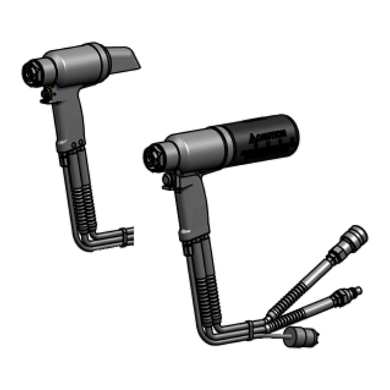
2600 series Hydraulic Installation Tool (HK914) -
Page 3: Safety Instructions
3. Be aware that failure of the workpiece, accessories, equipment. or the inserted tool itself can generate high velocity 2. Huck equipment must be maintained in a safe working projectiles. condition at all times. Tools and hoses should be 4. Always wear impact resistant eye protection during tool inspected at the beginning of each shift/day for operation. - Page 4 2600 series Hydraulic Installation Tool (HK914) Safety Instructions (continued) IV. REPETITIVE MOTION HAZARDS: instructions and as required by occupational health and 1. When using assembly power tool, the operator can safety regulations. experience discomfort in the hands, arms, shoulders, 4. Operate and maintain tool as recommended in the neck or other parts of the body.
-
Page 5: Specifications
(cm) Sticker Locations: The 2600 series tools are labeled with stickers that contain safety and pressure-settings information. These stickers must remain on the tool and be legible. Any sticker that becomes damaged or worn, or has been removed from the tool, or when replacing the cylinder, MUST be ordered and placed in the location shown below. -
Page 6: Principle Of Operation
2600 series Hydraulic Installation Tool (HK914) Principle of Operation PULL CYCLE Piston Travel When the Trigger Switch is pressed, pressurized Piston hydraulic fluid moves through the PULL hose to the front side of the Piston. The piston and nose assembly collet move rearward, installing the fastener. -
Page 7: Preparation For Use
A 30-minute training session with qualified personnel is recommended before hoses, couplers, using Huck equipment. and hydraulic fluid away from dirty When operating Huck equipment, always wear approved eye and hearing surfaces and free protection. of foreign matter. Ensure adequate clearance for the operator’s hands before proceeding. -
Page 8: Operating Instructions
2600 series Hydraulic Installation Tool (HK914) Operating Instructions FOR SAFE OPERATION, THIS SECTION MUST BE READ AND UNDERSTOOD. Bead UP Flange DOWN CORRECT CORRECT Do NOT install a fastener without a Do NOT pull a fastener workpiece (structure to be fastened), a pin, with the collar upside and a properly oriented collar in place. -
Page 9: Maintenance
Huck recommends ccessories - Follow the disassembly and assembly procedures in drying other parts before re-assembling. this manual. If Huck recommended procedures are not For additional information, see the appropriate Nose followed, the tool could be damaged. Assembly Data Sheet. -
Page 10: Disassembly Procedure
2600 series Hydraulic Installation Tool (HK914) Disassembly Procedure This procedure is for complete disassembly of the tool. 6. Remove the Pintail Deflector/Bottle by simultaneously Disassemble only those components necessary to replace twisting and pulling. damaged rings and worn or damaged components. -
Page 11: Assembly Procedure
2600 series Hydraulic Installation Tool (HK914) Assembly Procedure TO RE-ASSEMBLE THE TOOL: WARNING: Do not omit any seals during 1. Install the GLYD Ring Assembly on the piston. Place the servicing or re-assembly; leaks will result and special O-ring in the groove, and place the GLYD Ring serious personal injury can occur. - Page 12 CAUTION: Do NOT use Teflon tape on pipe ® Models 2600 & 2600-12 only: Use the Pintail Tube if threads. Tape can shred and break free into pintails will fall through. fluid lines, resulting in malfunctions.
-
Page 13: Components Drawings
2600 series Hydraulic Installation Tool (HK914) Components Drawing - 2600, 2600-12, 2600-16, 2600-16-3, 2600-16-12 Figure 6 501125 Back-up Ring 500831 122768 Rear Gland Assembly O-Ring (contains Gland and components labeled 122767 Front Gland Assembly (contains Gland and 500831 O-Ring 506158 Polyseal... - Page 14 2600 series Hydraulic Installation Tool (HK914) Components Drawing - 2600B Figure 7 501125 Back-up Ring 500831 122768 Rear Gland Assembly O-Ring (contains Gland and components labeled 122767 Front Gland Assembly 131296 508810 (contains Gland and 500831 O-Ring 506158 Polyseal components labeled...
-
Page 15: Troubleshooting
Have the appropriate kit accessible when using this tool and when performing maintenance on it. Huck also recommends having the following Accessories available when preparing, using, and performing maintenance on this tool. - Page 16 2600 series Hydraulic Installation Tool (HK914) Record your own notes here.
- Page 17 Determination is Outside USA and Canada made on a case-by case basis upon return of parts to Huck Contact your nearest Huck International location (see International, Inc. for evaluation.
- Page 18 8001 Imperial Drive Waco, TX 76714-8117 800-388-4825 254-776-2000 FAX: 254-751-5259 Huck is Forever, For the Long Haul, The Future regard to properties of the products shown Certified to of Fastening Technology, The Future of Assembly and/or the means for selecting such products,...
Need help?
Do you have a question about the 2600 and is the answer not in the manual?
Questions and answers