Sign In
Upload
Download
Table of Contents
Contents
Add to my manuals
Delete from my manuals
Share
URL of this page:
HTML Link:
Bookmark this page
Add
Manual will be automatically added to "My Manuals"
Print this page
×
Bookmark added
×
Added to my manuals
Manuals
Brands
Siemens Manuals
Controller
QAA75 series
Technical manual
Siemens QAA75 series Technical Manual
Albatros2. operator units / room units / auxiliary devices
Hide thumbs
Also See for QAA75 series
:
User manual
(138 pages)
1
2
Table Of Contents
3
4
5
6
7
8
9
10
11
12
13
14
15
16
17
18
19
20
21
22
23
24
25
26
27
28
29
30
31
32
33
34
35
36
37
38
39
40
41
42
43
44
45
46
47
48
49
50
51
52
53
54
55
56
57
58
59
60
61
62
63
64
65
66
67
68
69
70
71
72
73
74
75
76
77
78
79
80
81
82
83
84
85
86
page
of
86
Go
/
86
Contents
Table of Contents
Bookmarks
Table of Contents
Table of Contents
Siemens Operator / Room / Auxiliary Devices Ce1U2358En
1 Overview
2 Mounting and Installation
Wired Components
Room Unit QAA55
Room Unit QAA75
Operator Unit Avs37.29X
Operator Unit AVS37.394
Operator Unit AVS37.390
RF Components
Room Unit QAA58
Room Unit QAA78
RF Module AVS71.390
RF Module BSB AVS71.393
RF Repeater AVS14.390
RF Outside Sensor AVS13.399
Checking the RF Components
3 Handling
Qaa55
Operation
Programming
Qaa75
Operation
Programming
User Levels
Room Unit, Operator Unit Settings
Settings in Detail
Avs37.390
Operation
Programming
User Levels
Overview of the Settings
4 Technical Data
Operator Unit and Room Units Qaa5X
RF Module AVS71.390
RF Module BSB AVS71.393
RF Repeater AVS14.390
RF Outside Sensor AVS13.399
Index
Advertisement
Quick Links
1
Room Unit Qaa55
2
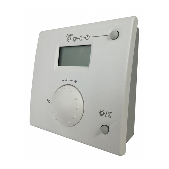
Room Unit Qaa75
3
Room Unit Qaa58
4
Qaa55
5
Programming
Download this manual
Albatros2
Operator units / Room units /
Auxiliary devices
Technical Manual
CE1U2358en_04
2014-09-26
Building Technologies
Table of
Contents
Previous
Page
Next
Page
1
2
3
4
5
Advertisement
Table of Contents
Need help?
Do you have a question about the QAA75 series and is the answer not in the manual?
Ask a question
Questions and answers
Related Manuals for Siemens QAA75 series
Thermostat Siemens Albatros RVS46 Series User Manual
Zone controller (138 pages)
Controller Siemens Synco 700 Series Basic Documentation
Communication via the knx bus (120 pages)
Controller Siemens QAA58 series Technical Manual
Albatros2. operator units / room units / auxiliary devices (86 pages)
Controller Siemens RVS41.813 User Manual
Avs75, avs37, qaa75, qaa78, qaa55 series heat pump controller (258 pages)
Controller Siemens QAA75.610 User Manual
Heat pump controller (221 pages)
Controller Siemens Albatros2 User Manual
Heat pump controller (221 pages)
Controller Siemens QAA78.610 User Manual
Heat pump controller (221 pages)
Controller Siemens QPA84 Product Information
Indoor air quality controller (21 pages)
Controller Siemens Desigo TRA QMX3.P36F Manual
Freely configurable flush-mounted room operator unit for knx pl-link (14 pages)
Controller Siemens TUTORbit POL687 Instructions For Installation, Use And Maintenance Manual
Cascade sequence, heating and cooling system controller (96 pages)
Controller Siemens Albatros 2 QAA75 Series User Manual
Boiler controllers (109 pages)
Controller Siemens SIPART PS2 Operating Instructions Manual
Electropneumatic positioners with profibus pa (330 pages)
Controller Siemens Micromaster Profibus Instruction Manual
Micromaster profibus optional board (67 pages)
Controller Siemens SIMATIC S7-1200 Getting Started
(60 pages)
Controller Siemens SIMATIC S7 System Manual
(796 pages)
Controller Siemens SIPART DR22 Assembly And Installation Information
(28 pages)
This manual is also suitable for:
Qaa58 series
Qaa55 series
Qaa78 series
Table of Contents
Save PDF
Print
Rename the bookmark
Delete bookmark?
Delete from my manuals?
Login
Sign In
OR
Sign in with Facebook
Sign in with Google
Upload manual
Upload from disk
Upload from URL


Need help?
Do you have a question about the QAA75 series and is the answer not in the manual?
Questions and answers