
Related Manuals for Siemens QAA75.610


Summarization of Contents
Summary
Product range overview
Overview of the available products and their interconnections within the system.
Safety notes
Notes on product liability
Information regarding the intended use and limitations of the products to avoid liability issues.
Mounting and installation
Regulations
General regulations and safety requirements for installing the units.
Heat pump controller RVS61.843
Specific engineering and mounting details for the RVS61.843 heat pump controller.
Extension module AVS75.390
Details on dimensions, drilling plans, and connection terminals for the AVS75.390 extension module.
Operator unit AVS37.294
Information on mounting, connections, and dimensions for the AVS37.294 operator unit.
Operator unit AVS37.390
Details concerning connections and dimensions for the AVS37.390 operator unit (PCB version).
Room unit QAA55…
Engineering, mounting, and connection details for the QAA55 room unit.
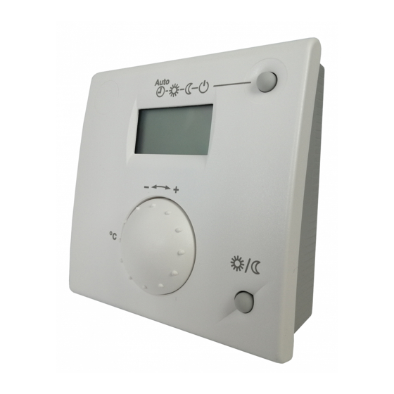
Room unit QAA75…
Installation and connection information for the QAA75 room unit.
RF components
Guidance on positioning wireless components for optimal transmission.
Commissioning
Heat pump controller RVS61.843
Steps and checks required for commissioning the RVS61.843 heat pump controller.
Handling
QAA75.. / QAA78… / AVS37..
Detailed operation instructions for QAA75, QAA78, and AVS37 units.
QAA55..
Operation guide for the QAA55 room unit, including controls and display.
The settings in detail
Time of day and date
Instructions for setting the controller's internal clock for accurate program operation.
Operator section
Configuration of settings related to language, info display, operation, and programming locks.
Radio links
Procedures for binding and testing wireless components within the system.
Time programs
Setting up switching programs for heating circuits and DHW.
Heating circuits
Details on setting operating modes, setpoints, heating curves, and ECO functions.
Cooling circuit 1
Configuration options for operating mode, setpoints, and release parameters for cooling.
DHW
Settings for DHW control, including setpoints, release, charging priority, and legionella function.
Hx pumps
Information on configuring Hx pumps, including excess heat draw and buffer tank interaction.
Swimming pool
Settings for swimming pool heating using solar or heat pump, including priority and plant hydraulics.
Primary controller / system pump
Configuration for primary controller and system pump integration with buffer storage tanks.
Heat pump
Details on heat pump types, function diagrams, and control parameters.
Condenser pump
Settings for condenser pump operation, including frost protection and overrun times.
Source pump
Configuration of source pump operation, including temperature limits and switching differentials.
Compressor control in plants without buffer or combi storage tank
Details on compressor control logic when no buffer or storage tank is present.
Compressor control in plants with buffer or combi storage tank
Compressor control logic when using buffer or storage tanks, including sensor usage.
Compressor settings
Parameters for compressor running times, switch-off temperatures, and sequence.
Compressor 2
Settings related to the second compressor stage, including locking and release conditions.
Electric immersion heater in the flow
Configuration for electric immersion heaters, including usage modes and control parameters.
Heat pump protection during DHW charging
Protection mechanisms for the heat pump during DHW charging operations.
General parameters
Parameters for compensating heat deficits and managing compressor cycles.
Defrost function for air-to-water HP
Details on the defrost mechanism for air-to-water heat pumps.
Automatic defrost function
How the automatic defrost sequence operates and is triggered.
Cooling
Information on active and passive cooling modes for heat pumps.
Cascade
Configuration settings for cascading heat sources, including priority and sequence.
Solar
Settings for solar collector operation, including charging control and frost protection.
Priority
Setting charging priorities for storage tanks and swimming pools.
Start function
Configuration for collector pump operation and frost/overtemperature protection.
Medium’s evaporation temperature
Settings related to the evaporation temperature and pump speed control.
Buffer storage tank
Parameters for buffer storage tank operation, including forced charging and protection.
Automatic locks
Settings for automatic generation and temperature differential locks.
Stratification protection
Functionality to maintain temperature stratification within the buffer storage tank.
Recooling
Settings for recooling temperatures and energy management.
DHW storage tank
Configuration for DHW storage tank, including abortion, charging control, and overtemperature protection.
Overtemperature protection
Settings to protect against overtemperature conditions in the DHW storage tank.
Electric immersion heater
Operation modes and release settings for electric immersion heaters.
Instantaneous DHW heater
Settings for instantaneous DHW heaters, including setpoints and pump speed control.
Mixing valve control
Parameters for mixing valve operation, including decrease, actuator type, and running time.
Configuration
Procedure
Steps for configuring the system, including plant diagram selection and parameter adjustment.
Heating / cooling circuit 1
Heating circuit 1
Settings to switch heating circuit 1 on and off.
Cooling circuit 1
Configuration for activating and operating cooling circuit 1.
Use of mixing valve 1
Defining the function of the mixing valve 1 for heating or cooling operations.
Heating circuit 2
DHW controlling element Q3
Setting the DHW control element to charging pump or diverting valve.
Separate DHW circuit
Configuration for using a heat source exclusively for DHW charging.
Heat pump
Heat source
Selection of the heat source type (Brine, Water, Air, External) for the heat pump.
Refrigeration
Defining whether refrigeration is generated and the system type (4-pipe or 2-pipe).
Solar
Solar controlling element
Selection of control method (charging pump or diverting valve) for solar integration.
External solar exchanger
Defining the use of external heat exchangers for DHW or buffer storage tanks.
Output relay QX
Relay outputs QX1 – QX6
Individual definition of functions for relay outputs QX1 through QX6.
QX extension module
Function output QX4-Mod
Setting the function for the modulated output QX4-Mod.
BX extension module
Sensor input BX1, BX2, BX3, BX4, BX5
Assignment of sensors to the BX inputs for system monitoring.
H2 extension module
Function input H2
Defining functions for input H2, including operating mode and signal logic.
10V output UX
Configuration for voltage-modulated output UX for pumps or temperature requests.
Types of sensor / readjustment
Sensor type collector
Selection and calibration of the collector sensor type.
Sensor readjustments
Adjusting measured values from connected sensors.
Frost protection for the plant
Air dehumidifier
Activation and deactivation of the air dehumidification function.
Sensors
Parameters
Saving or resetting parameters to default values.
Plant diagram
Check numbers
Explanation of check numbers used to identify current plant diagrams.
LPB system
Address / power supply
Configuration of device and segment addresses for LPB system communication.
Central functions
Action changeover functions
Defining the range of action for central changeover of operating modes.
Summer changeover
Specifying local or central action for summer changeover.
Optg mode changeover
Defining the range of action for operating mode changeover via input H.
Errors
Reset
Procedures for resetting alarms, heat pump errors, and relay alarms.
Error message functions
Details on monitoring setpoint and current temperature differences for error triggers.
Error history
Saving and retrieving the last 10 error entries with codes and timestamps.
Maintenance / special operation
Maintenance functions
Configurable functions for periodic plant monitoring and maintenance alerts.
Emergency operation
Emergency op function type
Manual or automatic control of emergency operation.
Input / output test
Output test relays
Testing the function and wiring of connected relays.
State of plant
Messages
Visualizing the current operating state of the plant through status displays.
Diagnostics cascade
Priority/state
Displaying priority and state of sources, temperatures, and stage order.
Diagnostics heat source
Brine-to-water heat pump
Checking operating states of components controlled via heat pump relays.
Compressor
Compressor sequence
Displaying the order of compressor operation.
Solar
Speed collector pump 1 / 2
Displaying the current speed of the collector pump.
Speed solar pump ext exch
Displaying the current speed of the external heat exchanger solar pump.
Speed solar pump buffer
Displaying the current speed of the solar pump for buffer storage tank charging.
Speed solar pump swi pool
Displaying the current speed of the solar pump for swimming pool heating.
Collector temperature 1 / 2
Displaying current and maximum/minimum collector temperatures.
Diagnostics consumers
Outside temperature
Display of current, min, max, attenuated, and composite outside temperatures.
Room
Display of relative room humidity, room temperature, and dewpoint temperature.
Heating circuits 1, 2, P
Display of the operating status of heating circuit pumps and valves.
DHW
Cooling circuit 1
Display of cooling circuit states, mixing valve, and flow temperature.
Plant diagrams
Basic diagrams
Selection of pre-defined plant diagrams for system configuration.
Heat / refrigeration source variants / extra functions
Information on heat/refrigeration source variations and additional system functions.
Technical data
Basic unit RVS61.843
Electrical and mechanical specifications for the RVS61.843 basic unit.
Extension module AVS75.390
Technical specifications for the AVS75.390 extension module.
Operator and room unit AVS37... / QAA7x… / QAA55..
Technical data for operator and room units including AVS37, QAA7x, and QAA55 series.
RF module AVS71.390
Technical specifications for the AVS71.390 RF module.
Wireless outside sensor AVS13.399
Technical data for the AVS13.399 wireless outside sensor.
RF repeater AVS14.390
Technical specifications for the AVS14.390 RF repeater.
Sensor characteristics
Electrical characteristics and resistance values for NTC and Pt1000 sensors.
Need help?
Do you have a question about the QAA75.610 and is the answer not in the manual?
Questions and answers