
Related Manuals for Siemens QAA78.610


Summarization of Contents
Summary
Product Range Overview
Provides an overview of the product range, including basic units, modules, and operator/room units.
Safety Notes
Notes on Product Liability
Outlines conditions for product use, requirements, and compliance with local regulations to avoid warranty voidance.
Mounting and Installation
Regulations
Covers electrical installation prerequisites, safety class requirements, and cable routing guidelines.
Heat Pump Controller RVS61.843
Details engineering considerations for air circulation, mounting methods, and electrical installation of the controller.
Connection Terminals RVS61.843
Shows terminal markings and connections for the RVS61.843 controller, including mains and low-voltage terminals.
RF Components
Explains placement criteria for wireless components to ensure interference-free transmission and optimal performance.
RF Module AVS71.390
Describes the RF module's function in extending product range with wireless communication, requiring cable connection.
Wireless Outside Sensor AVS13.399
Details the mounting method and connection for the wireless outside sensor.
RF Repeater AVS14.390
Explains the mounting, connection, and radio link establishment for the RF repeater.
Commissioning
Heat Pump Controller RVS61.843
Outlines steps for unit commissioning, including prerequisites, plant-specific settings, and function checks.
Handling
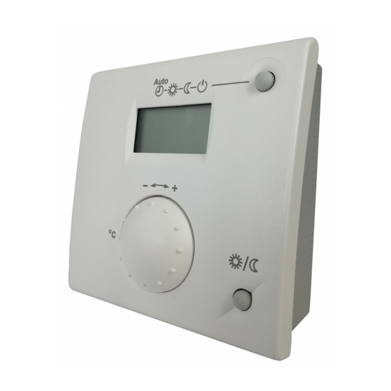
QAA75.. / QAA78… / AVS37..
Covers operation, displaying information, and adjusting settings for operator and room units.
Operation
Explains operating elements, display choices, and mode selections for room units and operator units.
Overview of the Settings
Provides a comprehensive table of available settings up to the heating engineer level, categorized by function.
The Settings in Detail
Time of Day and Date
Ensures correct heating program operation by setting time and date accurately.
Operator Section
Configuration of operator interface settings including language, info, locks, and device assignment.
Heating Circuits
Details functions available for heating circuits, including operating mode, setpoints, and room temperature adjustments.
Heating Curve
Adjust heating curve to match heat output and room temperature to user needs based on weather conditions.
DHW
Controls DHW temperature via time program or setpoint, with priority options and legionella function.
Heat Pump
Explains heat pump operation, function diagrams, and component designations for various heat sources.
Configuration
Configure plant diagrams by selecting presets, modifying partial diagrams, and fine-tuning parameters.
Plant Diagrams
Basic Diagrams
Presents basic diagrams showing heat source variants, extra functions, and component connections.
Plant Diagram 1
Illustrates a brine-to-water heat pump with a pump heating circuit, showing key components and connections.
Plant Diagram 10
Depicts an air-to-water heat pump system with DHW charging pump, showing heat source and circuit configurations.
Plant Diagram 19
Shows an air-to-water heat pump system with DHW diverting valve and solar collector, illustrating circuit connections.
Technical Data
Basic Unit RVS61.843
Provides detailed technical specifications for the RVS61.843 basic unit, including electrical and environmental data.
Sensor Characteristics
Lists temperature-resistance characteristics for various sensor types used with the system.
NTC 1 k
Presents the temperature-resistance data table for the NTC 1 k sensor.
NTC 10k
Presents the temperature-resistance data table for the NTC 10k sensor.
Need help?
Do you have a question about the QAA78.610 and is the answer not in the manual?
Questions and answers