Megger SVERKER 900 Application Note
Relay and substation test system.current transformer testing
Hide thumbs
Also See for SVERKER 900:
- User manual (56 pages) ,
- Technical manual (33 pages) ,
- Quick manual (4 pages)
Advertisement
Quick Links
Download this manual
See also:
User Manual
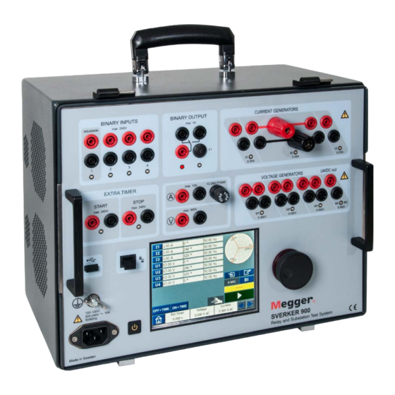
SVERKER 900
Relay and Substation Test System
Application Note
Current transformer testing
This application note gives examples on how to
perform some typical tests on current transformers
(CTs) with SVERKER 900. These tests are common to
perform for instance during commissioning.
Important
Read and comply with the safety instruc-
tions in the User's manual.
Test procedures
Tests to be done at commissioning
▪
Wiring check and visual inspection
▪
Polarity test with DC current or AC voltage
▪
Burden impedance test
▪
Magnetization curve test
▪
Primary injection test with load connected
Other tests
▪
Secondary resistance test (RCT)
▪
Primary injection - Ratio test with AC current or voltage
(no load connected)
Required equipment for testing
▪
SVERKER 900
Subject to change without notice. Printed matter No. ZR-CR03E
Wiring check and visual inspection
1]
Check that the primary and secondary side
are connected for correct ratio according to
system requirements.
2]
Check the tightness for secondary connec-
tions, including grounding and shorting links.
3]
Check that each core is connected to correct
load according to drawings.
4]
Check that each core are grounded in only
one point on secondary side and close to
CT location. For CT secondaries connected
together the grounding shall be done at
relay point, for exampel cores connected to
differential protection.
Current transformer data
Relay core
5P and 10P
Measuring core 0.3 B
n
Accuracy limit factor (ALF) for relay cores
Safety factor (SF) for measuring cores
Doc. CR033089BE
V01 2015
Advertisement

Subscribe to Our Youtube Channel
Related Manuals for Megger SVERKER 900


Summary of Contents for Megger SVERKER 900
- Page 1 Wiring check and visual inspection perform some typical tests on current transformers Check that the primary and secondary side (CTs) with SVERKER 900. These tests are common to are connected for correct ratio according to perform for instance during commissioning.
- Page 2 Polarity test with DC current Polarity test is made to confirm the polarity mark- Select I1 on and set "0" in frequency field to ing on the CT (primary and secondary) and verify it get DC current. is matching with the drawing. This is very important Set DC current to a value about 5-10% of when it comes to directional and differential protec- primary CT current.
- Page 3 Secondary resistance test (RCT) Secondary resistance test is made to verify continuity and the value is used for calculating knee-point. Connect according to picture below. Reverse connection on P1 and P2 and check that the value is negative for current. Repeat test for all phases and cores.
- Page 4 Magnetization curve test Inject current until stabilized value is ob- tained on voltage and current meters. A magnetization curve test is made to confirm the magnetization characteristics of a CT. This test shall be conducted before ratio test and after secondary resistance and polarity test, since residual magnetism left in the core after DC test (polarity, resistance) otherwise gives error in the ratio test.
- Page 5 Magnetization test Automatic mode Press the knob symbol to change to auto. The magnetization test can be made manual or in auto mode. Press and the curve will be automati- cally plotted. Manual test Repeat test for all phases and cores. Press and turn the knob according to arrow symbol.
-
Page 6: Polarity Test
Polarity test with AC voltage Make the same test for the connection be- low, the VAM-meter should show the same value. Polarity test Connect according to picture below. Change connection on CT secondary side, see below. With this connection the angle between voltage and current for secondary side are measured. - Page 7 Burden impedance test Demagnetization Connect according to picture below. A burden test is made to ensure that the load (VA) is not more than specified on nameplate. Connect according to picture below. Press to start the test. Press on voltage parameter. When it turns yellow, slowly turn knob clockwise to in- crease voltage.
- Page 8 Ratio test - Primary injection no load connected This test is to verify the turns ratio of the CT. Make connections as shown in figure below. Note CT-cores not included in test should be shorted. Inject current until stabilized value is ob- tained on voltage and current meters.
- Page 9 Primary injection test – with load connected This test is to ensure the CT circuits are properly con- nected with respected cores and there is no mix up in the circuit (phase identification). The ratio test can also be done here. Note High impedance relays shall be shorted during the primary injection test.
- Page 10 Connection L1-L2 Connection L2-L3 Core identification When one CT has several cores used for different purposes the cores can be identified during primary injection test. Inject 10% of rated primary current between phase to earth (ground) with all burdens connected. Short one of the cores at the CT terminal.
- Page 11 CR033089BE ZR-CR03E SVERKER 900...
- Page 12 NOTICE OF COPYRIGHT & PROPRIETARY RIGHTS © 2014-2015, Megger Sweden AB. All rights reserved. The contents of this document are the property of Megger Sweden AB. No part of this work may be reproduced or transmitted in any form or by any means, except as permitted in written license agreement with Megger Sweden AB.
Need help?
Do you have a question about the SVERKER 900 and is the answer not in the manual?
Questions and answers