Advertisement
Quick Links
1、 General.........................................................................................................
2、 Safety Note...................................................................................................
3、 Safety Symbol Description ...........................................................................
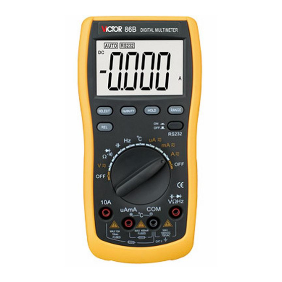
4、 Front Panel Description.................................................................................
5、 Button Function Description ...........................................................................
6、 Other Function................................................................................................
7、 Measurement Operation....................................................................................
(1)、ACV/DCV Measurement ..............................................................................
(2)、ACA/DCA Measurement ..............................................................................
(3)、Resistance Measurement ........................................................................
(4)、Diode Measurement .................................................................................
(5)、Continuity Measurement ........................................................................
(6)、Capacitance Measurement ........................................................................
(7)、Frequency/Duty Circle Measurement.........................................................
(8)、Temperature Measurement ........................................................................
8、 Property......................................................................................................
9、 Instrument Maintenance.................................................................................
10、
Defect Elimination.................................................................................
一、General
It is a good performance and Auto Range 3 3/4 digital instrument with USB interface, driven by battery.
It adopts the LCD with 42mm high figure to make the reading very clear and it possesses the Data Hold
and Auto Power Off function to make the use more convenient.
This instrument has the function of measuring ACV, DCV, ACA, DCA, Resistance, Capacitance, Temperature,
Index
1
Advertisement

Subscribe to Our Youtube Channel
Related Manuals for Victor 86B


Summary of Contents for Victor 86B
- Page 1 Index 1、 General…………………………………………………………………………………………… 2、 Safety Note……………………………………………………………………………………… 3、 Safety Symbol Description ………………………………………………………………… 4、 Front Panel Description……………………………………………………………………… 5、 Button Function Description ………………………………………………………………… 6、 Other Function…………………………………………………………………………………… 7、 Measurement Operation………………………………………………………………………… (1)、ACV/DCV Measurement …………………………………………………………………… (2)、ACA/DCA Measurement …………………………………………………………………… (3)、Resistance Measurement ……………………………………………………………… (4)、Diode Measurement ……………………………………………………………………… (5)、Continuity Measurement ……………………………………………………………… (6)、Capacitance Measurement ……………………………………………………………… (7)、Frequency/Duty Circle Measurement………………………………………………… (8)、Temperature Measurement ……………………………………………………………… ...
- Page 2 Diode, Continuity, Frequency, and Duty Circle, etc. It takes the dualintegral A/D Converter as core, is an excellent tool and most and possesses the Auto Range and Manual Range selection function. It suitable for lab, factory, maintenance and repair users. 二、 Safety Note The instrument meets the standard of IEC1010 (safety standard promulgated by the International Electrician Committee). Please read the safety notes carefully before operation. 1. When measuring each range, do not input the value over the range limit. 2. It is prerequisite to make sure the test lead connects reliably, links up correctly, insulates properly to avoid the electric shock when measuring the voltage higher than 36V DC and 25V AC. The voltage less than 36V is safety voltage. 3. Be sure to keep the test leads off the tested point when converting the function and range. 4. Select the correct function and range to avoid fault operation. Even thought this instrument has the fullfunction protection, please pay your close attention when measuring for your safety.
- Page 3 uA/mA and Temperature input terminal: Measuring AC/DC uA/mA and Temperature positive input terminal, insert the red test lead. 6. CO M input terminal: negative input terminal, insert the black test lead. VΩHz input terminal: measure Voltage, Frequency/Duty Circle, Resistance, Capacitance, Diode and Continuity positive input terminal, insert the red test lead. 五、Button function description (1) SELECT: When there are two or more measuring functions compound at one range, press the button to switch the measuring function. (2) RANGE: Auto Range/ Manual Range switch, the default is set as Auto Range mode when turning on. Press the button and switch to Manual Range. Press the button once, the range is switched to the higher one at the mode, press the button again to switch the range to the lowest one when measuring the highest range, the cycle is in proper order from low to high. Keep pressing the button more than 2 seconds, return to Auto Range mode. There is no Auto Range mode at Frequency and Capacitance range. (3) R EL: Relative Value measuring button. (4) HZ/DUTY: Frequency/Duty Circle selection button, press the button to switch between the Frequency and Duty Circle mode at Frequency Range; Press the button to switch to Voltage/Frequency/Duty Circle or Current/Frequency/Duty Circle model at AC/DC Voltage or AC/DC Current Range. (5) HOLD: Date Hold button, press the button, the value is held on LCD; Press the button again, exit the hold mode and get into the normal measuring status. (6) RS232: serial output control button, worked at the locked mode. When the button is close, RS232 symbol is displayed on LCD, it indicates the instrument is getting into ...
- Page 4 A) Turn the function/range selection knob to , the default is set as DCV measurement, if measuring ACV, press SELECT button to make it at the status of ACV measurement, displayed as the following pictures. B) Insert the red and black test lead separately to VΩ Hz and COM input terminal. Connect the test lead to the tested circuit or power in parallel, the polarity of the red test lead and the tested voltage value will be displayed on LCD simultaneously. D) A t the Manual Range mode, if “OL” is displayed on LCD, it indicates the tested voltage value has exceeded the present range limit, please select the higher range to complete the measurement.
- Page 5 Connect the test lead to the tested circuit or power in series, the polarity of the red test lead and the tested current value will be displayed on LCD simultaneously. D) A t the Manual Range mode, if “OL” is displayed on LCD, it indicates the test current value has exceeded the present range limit, please select the higher range to complete the measurement. Read the present test result from LCD. Note: l Do not measure the current higher than 10A at Range 10A and higher than 400mA at uA and mA Range, otherwise the fuse will be burnt out or the instrument will be damaged. l When measuring the high current, the time of each measurement can’t be over 10 seconds, and the interval of each measurement should be longer than 15 seconds. l Cut the connection between the test lead and tested circuit at once after measurement. 1.
- Page 6 Ω Turn the function/range selection knob to Insert the red and black test lead separately to VΩ Hz and COM input terminal. Press the SELECT button to choose the diode measurement function, displayed as the following pictures. D) Connect the RED test lead to the positive pole of the tested diode, BLACK test lead to the negative pole. Read the present test result from LCD. Note: l If the diode is open circuit or the polarity is connected counter, “OL” will be displayed on LCD. l When measuring the incircuit diode, make sure the power of circuit has been turned off and all capacitors are fully discharged. l Cut the connection between the test lead and tested circuit at once after measurement. 5.
- Page 7 l When detecting the continuity of the circuit, make sure the power of circuit has been turned off and all capacitors are fully discharged. l Cut the connection between the test lead and tested circuit at once after measurement. 5. Capacitance Measurement Turn the function/range selection knob to Capacitance Range, displayed as the following picture. Insert the red and black test lead separately to VΩ Hz and COM input terminal. Connect the test lead to the tested capacitor in parallel, the tested capacitor value will be displayed on LCD.
- Page 8 the users. l Cut the connection between the test lead and tested circuit at once after measurement. 7. Temperature Measurement Turn the function/range selection knob to Temperature Range, displayed as the following picture. B) Insert the red and black temperature sensor separately to uAmA and COM input terminal. C) C onnect the sensor of the temperature cable to the surface or inside of the tested object. Read the present test result from LCD. Note: l ...
- Page 9 1.Technic Feature Accuracy: (a% × reading + digits) at 23 ± 5 , relative humidity <75%. One year calibration guarantee since the time dispatched from the factory. 2-1 DC Voltage (DCV) Range Accuracy Resolution 400mV 0.1mV 4V 1mV ±(0.5%+4d) 40V 10mV 400V 100mV 1000V ±(1.0%+6d) 1V Input impedance: 10MΩ . Overload protection: 1000V DC or 750V AC peak value.
- Page 10 ±(0.8%+5d) 400Ω 0.1Ω 4KΩ 1Ω 40KΩ 10Ω ±(0.8%+4d) 400KΩ 100Ω 4MΩ 1KΩ ±(1.2%+10d) 40MΩ 10KΩ Open circuit voltage: 400mV. Overload protection: 250V DC/AC peak value. Note: At Range 400Ω ,shortcircuit the test lead to measure the wire resistance, and then subtract it from the real measurement. 2-6 Capacitance (C) Range Accuracy Resolution 50nF ±(5.0%+50d) ...
- Page 11 less than 30Ω Overload protection: 250V DC/AC peak value. 九、Instrument Maintenance This is a highly precise instrument, do not try to modify the inner circuit at will. Keep the instrument dry, and keep it away form dust and shock. Do not store and use the instrument in high humility, high temperature, combustible, explosive and strong magnetic places. Clean the surface of the instrument with the damp cloth and gentle detergent, do not use the strong solvent like the abrasive cleaner and alcohol, etc. Take out the batteries if do not use the instrument for a long time to prevent the batteries from leaking the liquid to corrode the instrument. When LCD displays “ “ symbol, should replace the batteries as the following steps: 4-1-1 Loose the screw that fixes the batteries, and remove the battery case.
Need help?
Do you have a question about the 86B and is the answer not in the manual?
Questions and answers