Table of Contents
Advertisement
Advertisement
Table of Contents

Related Manuals for Cembre ROLLY 3000


Summary of Contents for Cembre ROLLY 3000
- Page 1 THERMAL TRANSFER PRINTER ROLLY 3000 OPERATION AND MAINTENANCE MANUAL ENGLISH...
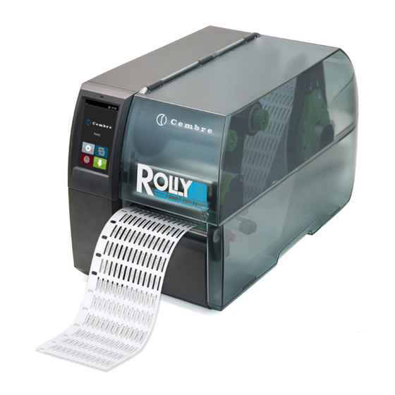
- Page 2 Cembre is designed for the volume printing of cables markers and adhesive labels. ROLLY 3000 Robust and quiet, Rolly3000 provides reliable, intensive operation in offi ce or factory combined with the facility to optimise printer set-up according to the media.
-
Page 3: Table Of Contents
Media dimensions ..........................24 Device dimensions ..........................25 Refl ex mark dimensions ......................... 26 Conformity ............................27 Reference to the EU Declaration of Conformity ..................27 FCC ................................ 27 Warranty ..............................27 Return to Cembre for repair ........................ 27 Accessories ............................27... -
Page 4: Introduction
Introduction Instructions Important information and instructions in this documentation are designated as follows: Danger! Draws attention to an exceptionally great, imminent danger to your health or life due to hazardous voltages. Danger! Draws attention to a danger with high risk which, if not avoided, may result in death or serious injury. Warning! Draws attention to a danger with medium risk which, if not avoided, may result in death or serious injury. -
Page 5: Safety Instructions
Introduction Safety Instructions • The device is confi gured for voltages of 100 to 240 V AC. It only has to be plugged into a grounded socket. • Only connect the device to other devices which have a protective low voltage. •... -
Page 6: Installation
Installation Device Overview 1 Cover 2 Margin stop (only devices with centered media guiding) 3 Margin stop 4 Roll retainer 5 Ribbon supply hub 6 Ribbon take-up hub 7 Print unit 8 Cover 9 Touchscreen display 10 LED "Power on" Figura 1 Figure 1 Overview... - Page 7 Installation 12 11 Ribbon defl ection 13 12 Printhead retainer with printhead 14 13 Label sensor 15 14 Allen key 16 15 Printhead locking lever 17 16 Print roller 18 17 Guide adjusting knob 19 18 Guide 20 19 Dispense plate Figura 2 Figure 2 Print unit...
-
Page 8: Unpacking And Setting-Up The Printer
Installation Unpacking and setting-up the printer Lift the label printer out of the box. Check label printer for damage which may have occurred during transport. Set up printer on a level surface. Remove foam transportation safeguards near the printhead. ... -
Page 9: Connecting The Device
Installation Connecting the Device The standard available interfaces and connectors are shown in Figure 3. 1.7.1 Connecting to the Power Supply The printer is equipped with a wide area power unit. The device can be operated with a supply voltage of 230 V~/50 Hz or 115 V~/60 Hz without adjustment. -
Page 10: Touchscreen Display
Touchscreen Display The user can control the operation of the printer with the control panel, for example: • Issuing, interrupting, continuing and canceling print jobs, • Setting printing parameters, e.g. heat level of the printhead, print speed, interface confi guration, language and •... - Page 11 Touchscreen Display With special software or hardware confi gurations additional symbols appear on the start screen: Direct cut with CU, PCU or ST cutter installed Figura 5 Optional symbols on the start screen Figure 5 Release a direct cut without media feed. Tabella 2 Table 2 Optional symbols on the start screen...
-
Page 12: Navigation In The Menu
Touchscreen Display 1.10 Navigation in the Menu Start level Selection level Parameter/function level Figura 7 Figure 7 Menu levels To open the menu select on the start screen. Select a theme in the selection level. Several themes have substructures again with selection levels. To return from the current level to the upper one select . -
Page 13: Loading Material
Loading Material Notice! For adjustments and simple installation work, use the accompanying Allen key located in the top section of the print unit. No other tools are required for the work described here. 1.11 Loading Media from Roll 1.11.1 4.1.1 Positioning the Media Roll on the Roll Retainer Figura 9 Figure 9... -
Page 14: Inserting A Label Strip Into The Printhead
Loading Material 1.11.2 4.1.2 Inserting the Media into the Printhead Figura 10 Figure 10 Inserting the media into the printhead 1. Turn lever (2) counterclockwise to lift the printhead. 2. Adjust the guide(s) (6) with the knob (7) in such a way that the media can pass between the two guides. 3. -
Page 15: Setting The Label Sensor
Loading Material 1.11.4 4.1.3 Setting the Label Sensor The label sensor can be shifted perpendicular to the direction of paper fl ow for adaptation to the media. The sensor unit (1) of the label sensor (Ref. to Fig. 10) is visible from the front through the print unit and is marked with an inden- tation in the label sensor retainer. -
Page 16: Loading Ribbon
Loading Material 1.12 Loading Transfer Ribbon Notice! With direct thermal printing, do not load a transfer ribbon; if one has already been loaded, remove it. Figura 11 Figure 13 Loading transfer ribbon 1. Clean printhead before loading the transfer ribbon ( 6.3 on page 19). 2. -
Page 17: Setting The Feed Path Of The Ribbon
Loading Material 1.13 Setting the Feed Path of the Transfer Ribbon Transfer ribbon wrinkling can lead to print image errors. The transfer ribbon defl ection (3) can be adjusted so as to prevent wrinkles. Figura 13 Figure 15 Setting the feed path of the transfer ribbon Notice! The adjustment is best carried out during printing. -
Page 18: Printing Operation
Printing Operation Attention! Printhead damage caused by improper handling! Do not touch the underside of the printhead with the fi ngers or sharp objects. Ensure that the labels are clean. Ensure that the label surfaces are smooth. Rough labels act like emery paper and reduce the service life of the printhead. -
Page 19: Cleaning
Cleaning 1.16 Cleaning Information Danger! Risk of death via electric shock! Disconnect the printer from the power supply before performing any maintenance work. The label printer requires very little maintenance. It is important to clean the thermal printhead regularly. This guarantees a consistently good printed image and plays major part in preventing premature wear of the printhead. -
Page 20: Cleaning The Label Sensor
Cleaning 1.19 Cleaning the Label Sensor Attention! Label sensor can be damaged! Do not use sharp or hard objects or solvents to clean the label sensor. The label sensor can become dirtied with paper dust. This can adversely affect label detection. Figura 14 Figure 16 Cleaning the label sensor... -
Page 21: Fault Correction
Fault Correction 1.20 Error Display The appearance of an error will be shown on the display: Figura 15 Figure 17 Error display The error treatment is pending on the error type 7.2 on page 21. The display offers the following possibilities to continue after an error occurred: Repeat The print job will be continued after clearing the error cause. - Page 22 Fault Correction Error message Cause Remedy No label found Press Repeat repeatedly until printer recognizes the There are labels missing on the label material next label on the material. The label format as set in the software Cancel current print job. does not correspond with the real label Change the label format set in the software.
-
Page 23: Problem Solution
Fault Correction 1.22 Problem Solution Problem Cause Remedy Transfer ribbon creases Transfer ribbon defl ection not adjusted Adjust the transfer ribbon defl ection. 4.3 on page 17 Head locking system not adjusted Adjust the head locking system. Transfer ribbon too wide Use a transfer ribbon slightly wider than the width of label. -
Page 24: Media
Media 1.23 Media Dimensions Labels Endless material / Shrink tubes Figura 16 Media dimensions Figure 18 Dim. Designation Dimensions in mm Label width 4 -110 Label height 4 - 2000 in peel-off mode 12 - 200 Tear-off length > 30 Cut length with cutter >... -
Page 25: Device Dimensions
Media 1.24 Device Dimensions Gap sensor & Refl ective sensor Printhead Peel-off edge Tear-off edge Cut edge Figura 17 Device dimensions Figure 19 Dim. Designation Dimensions in mm Distance printhead - peel-off edge 13,5 Distance printhead - tear-off edge 13,5 Distance printhead - cut edge with cutter CU 20,5... -
Page 26: Refl Ex Mark Dimensions
Media 1.25 Refl ex Mark Dimensions Labels with refl ex marks Endless material with refl ex marks virtual label front edge refl ex mark Figura 18 Refl ex mark dimensions Figure 20 Dim. Designation Dimensions in mm Label distance > 2 Distance between print zones >... -
Page 27: Conformity
Service Centre; if possible, attach a copy of the Test Certifi cate supplied by Cembre together with the printer or, if no other references are available, indicate the approximate purchase date and serial number. - Page 28 CS 92014 – 91423 Morangis Cédex E-mail: sales@cembre.com E-mail: sales@cembre.co.uk E-mail: info@cembre.fr www.cembre.it www.cembre.co.uk www.cembre.fr Cembre España S.L.U. Cembre GmbH Cembre Inc. Calle Verano, 6 y 8 - P.I. Las Monjas Heidemannstraße 166 Raritan Center Business Park 28850 Torrejón de Ardoz - Madrid (España) 80939 München (Deutschland)
Need help?
Do you have a question about the ROLLY 3000 and is the answer not in the manual?
Questions and answers
EVERY TIME I PLUG THE USB INTO MY LAPTOP THE PRINTRT STSRTS PRINTING AN UNWANTED JOB WITH THOUSANDS OF LABELS. HOW DO I STOP THIS??