
Subscribe to Our Youtube Channel
Related Manuals for Solid State Logic Alpha-Link AX

Summary of Contents for Solid State Logic Alpha-Link AX
- Page 1 XLogic Alpha-Link AX / MADI-AX / MADI-SX / LIVE User Guide XLogic Alpha-Link. This is SSL.
-
Page 3: Table Of Contents
I I n n t t r r o o d d u u c c t t i i o o n n Virtual Switches, Page One (Alpha-Link AX, MADI-AX and MADI-SX) S S c c o o p p e e... - Page 5 Introduction Congratulations on your purchase of this Solid State Logic Alpha-Link Audio I/O unit. Please be assured that it will provide you with many years of reliable service while delivering the pristine audio quality you expect from any Solid State Logic product.
- Page 6 Registration will also make you eligible for technical support. The Solid State Logic home page is at: www.solidstatelogic.com From there you can access our Support page, which includes links to the Product Registration and Download pages.
-
Page 7: I/O Capabilities
I/O Capabilities The number of channels available on each audio interface provided by the Alpha-Link is determined by the sample rate and in certain circumstances by the mode of operation chosen. external clock source, each unit can also operate at a deviation of up to ±10% from these rates. Throughout this guide Each unit can operate at one of four nominal sample rates;... -
Page 8: A A P P P P E E N N D D I I X X B B - - T T R R O O U U B B L L E E S S H H O O O O T T I I N N G
Installation Notes Please take time to read through this guide before installing your Alpha-Link. If however you are unable to resist that temptation, do take note of the following points: • Full connector pin-out details are provided in the Installation Guide. •... -
Page 9: Power Switch
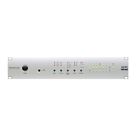
Front Panel The front panels of each model of Alpha-Link are all broadly similar, differing only to reflect the different I/O options provided (the unit illustrated here being an Alpha-Link MADI-SX). Routing Matrix Clock Source Power Switch Control Selection Headphones Sample Rate Signal Meters (except Alpha-Link LIVE) -
Page 10: Headphones
Headphones A headphone socket is provided on all units apart from the Alpha-Link LIVE. This connector is a standard 0.25" headphone jack socket and provides a stereo signal derived from analogue output channels 23 (Left) and 24 (Right). The headphone signal level is fixed and can only be controlled in the digital domain by a suitable controller such as the SSL Mixer software via an SSL (or Soundscape) Mixpander card. -
Page 11: Viewing And Setting Routing
Viewing and Setting Routing Pressing the OUTPUT button repeatedly will cycle through the available output groups, the currently selected output group being indicated by the corresponding LED. For each output group, the LEDs of the input column will indicate which input group(s) are connected to that output group. To set or change the input group(s) connected to a given output group: •... -
Page 12: Clock Source Selection
Clock Slave device locked to an external clock signal. Possible external sources are: Internal External • ADAT (Alpha-Link AX and MADI-AX) (MADI or Wordclock) • AES/EBU (Alpha-Link MADI-SX and LIVE) • MADI (Alpha-Link MADI-AX, MADI-SX and LIVE) •... -
Page 13: Sample Rate Selection
Sample Rate Selection The sample rate indicators show the current sample rate of the unit. When the 44.1kHz Alpha-Link clock source is set to ‘Internal’ (see opposite), pressing the SAMPLE RATE button will step through each available sample rate (44.1kHz, 48kHz, 88.2kHz 48kHz and 96kHz) –... -
Page 14: Signal Meters
Signal Meters The meter section of the front panel provides simple tri-colour LED metering for either the 24 analogue inputs (AD) or the 24 analogue outputs (DA), selectable using the METERS button. Input Metering Output Metering Tri-colour LED Meters (24 Channels) For each input or output channel, the signal level is represented by the state of the LED with the corresponding number. -
Page 15: Diagnostic Mode
System Settings and Diagnostics Each Alpha-Link unit is configured by default to Current option settings for the work in a simple system. Many users however selected page may find that these defaults are not appropriate for their setups. To cater for such situations, the default settings may be adjusted using a set of XS LED virtual switches, accessed from the Alpha-Link... -
Page 16: Selecting An Option
Selecting an Option For each page of switches, the middle row of meter LEDs indicates, in RED, the currently selected switch such that Channel 9 LED indicates Switch 1, Channel 10 indicates Switch 2 etc. Pressing the OUTPUT button will cycle through all switches for that page. -
Page 17: Firmware Version
Firmware Version Whilst in diagnostic mode, the Alpha-Link unit can also be set to display the LEDs Number current firmware version by simultaneously pressing both the SAMPLE RATE and CLOCK buttons. The firmware version will be displayed across the top row of meter LEDs (1 through 8) whilst the buttons are pressed;... -
Page 18: Virtual Switches, Page One (Alpha-Link Ax, Madi-Ax And Madi-Sx)
Virtual Switches, Page One (Alpha-Link AX, MADI-AX and MADI-SX) Settings in bold indicate defaults. Please also refer to the notes overleaf for details regarding each setting. Option Setting LED State See Note 64 (32 at 2Fs) Number of MADI channels (not AX) -
Page 19: Virtual Switches, Page One (Alpha-Link Live)
Virtual Switches, Page One (Alpha-Link LIVE) Settings in bold indicate defaults. Please also refer to the notes opposite for details of each setting. Option Setting LED State See Note 64 (32 at 2Fs) Number of MADI channels 56 (28 at 2Fs) High Speed MADI 2Fs data format Legacy (SMUX) -
Page 20: Notes For Virtual Switches, Page One
1. There are two MADI channel formats; 56 or 64 channel. The 56 channel format allows for ±10% deviation from Notes for Virtual Switches, Page One the nominal sample rate whilst the 64 channel format uses the full capacity of the MADI stream fixed to the selected sample rate. - Page 21 3. When both analogue and digital (either ADAT or AES/EBU) input groups are both connected to the Expansion Bus or MADI output groups, this option determines which input group feeds the output group first and hence affects the order in which input channels are assigned to channels on the Expansion Bus or the MADI stream. Similarly, when the Expansion Bus or MADI input groups are routed to both the analogue and ADAT output groups, this switch also determines the order in which the input channels are split across the selected output groups.
-
Page 22: Virtual Switches, Page Two (Alpha-Link Ax And Madi-Ax)
Virtual Switches, Page Two (Alpha-Link AX and MADI-AX) Settings in bold indicate defaults. Please refer to the notes overleaf for details regarding each setting. Option Setting LED States See Note ADAT In 1 – 8 ADAT clock source ADAT In 9 – 16 ADAT In 17 –... -
Page 23: Virtual Switches, Page Two (Alpha-Link Madi-Sx And Live)
Virtual Switches, Page Two (Alpha-Link MADI-SX and LIVE) Settings in bold indicate defaults. Please also refer to the notes overleaf for details regarding each setting. Option Setting LED States See Note AES/EBU In 1 & 2 AES/EBU In 3 & 4 AES/EBU clock source (port ‘A’... -
Page 24: Notes For Virtual Switches, Page Two
Notes for Virtual Switches, Page Two 1. Because the Alpha-Link AX and MADI-AX units carry three ADAT ports, there are three ports to choose from when selecting an ADAT clock source. To enable one of the three ports to be selected the first two option switches operate together. -
Page 25: Virtual Switches, Page Three (Alpha-Link Live)
Virtual Switches, Page Three (Alpha-Link LIVE) Settings in bold indicate defaults. Please also refer to the notes below for details regarding each setting. Option Setting LED States See Note MADI Control Host Expansion Bus Unused – Unused – Unused – Unused –... -
Page 27: Inputs With Sample Rate Conversion
Appendix A – AES/EBU Interface Inputs with Sample Rate Conversion The inputs of AES/EBU port A (channels 1 through 8) have sample rate conversion available. These sample rate converters combine a wide input-to-output sampling ratio with outstanding dynamic range and ultra low distortion, resulting in high quality even at a 1:1 conversion (where many SRCs offer their lowest quality). - Page 28 If so, it is normal for these controls to be deactivated. The Clock button does not work. Otherwise, please contact Solid State Logic’s technical support. The Sample Rate button does not work. The Alpha-Link firmware needs to be updated. Firmware...
-
Page 29: Support Faqs
Support FAQs To access the latest support information on Alpha-Link, please visit our online support site: www.solidstatelogic.com/support The information that you will find there is kept up to date by our support staff to make sure all information is accurate. All information is available to you 24 hours a day, 7 days a week. - Page 31 Appendix C – Alpha-Link Model Numbers Alpha-Link is available in a variety of configurations. The following table correlates the major differences between the different models with the unit part numbers to aid identification of units: SSL Part Number 1 Unit Identifier 2 Analogue I/O Level 3 Model Digital Interfaces...
- Page 32 All Rights reserved under International and Pan-American Copyright Conventions C10 HD, Mixpander, SSL, Solid State Logic, XLogic, XLogic Alpha-Link and XLogic Alpha-Link 8-RMP are trademarks of Solid State Logic All other product names and trademarks are the property of their respective owners and are hereby acknowledged...
Need help?
Do you have a question about the Alpha-Link AX and is the answer not in the manual?
Questions and answers